window JEEP RENEGADE 2023 Owner's Manual
[x] Cancel search | Manufacturer: JEEP, Model Year: 2023, Model line: RENEGADE, Model: JEEP RENEGADE 2023Pages: 364, PDF Size: 18.65 MB
Page 85 of 364
STARTING AND OPERATING 83
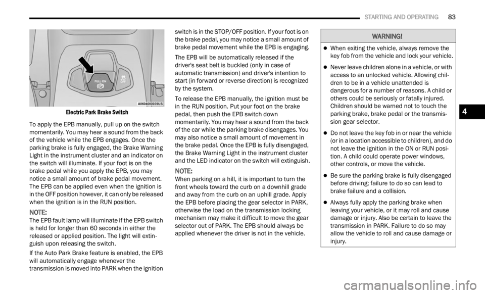
Electric Park Brake Switch
To apply the EPB manually, pull up on the switch
momenta
rily. You may hear a sound from the back
of the vehicle while the EPB engages. Once the
parking brake is fully engaged, the Brake Warning
Light in the instrument cluster and an indicator on
the switch will illuminate. If your foot is on the
brake pedal while you apply the EPB, you may
notice a small amount of brake pedal movement.
The EPB can be applied even when the ignition is
in the OFF position however, it can only be released
when the ignition is in the RUN position.
NOTE:
The EPB fault lamp will illuminate if the EPB switch
is he l
d for longer than 60 seconds in either the
released or applied position. The light will extin -
guish upon releasing the switch.
If the Auto Park Brake feature is enabled, the EPB
w ill a
utomatically engage whenever the
transmission is moved into PARK when the ignition switch is in the STOP/OFF position. If your foot is on
the brake pedal, you may notice a small amount of
brake pedal movement while the EPB is engaging.
The EPB will be automatically released if the
drive
r
's seat belt is buckled (only in case of
automatic transmission) and driver's intention to
start (in forward or reverse direction) is recognized
by the system.
To release the EPB manually, the ignition must be
in th e
RUN position. Put your foot on the brake
pedal, then push the EPB switch down
momentarily. You may hear a sound from the back
of the car while the parking brake disengages. You
may also notice a small amount of movement in
the brake pedal. Once the EPB is fully disengaged,
the Brake Warning Light in the instrument cluster
and the LED indicator on the switch will extinguish.
NOTE:
When parking on a hill, it is important to turn the
front w
heels toward the curb on a downhill grade
and away from the curb on an uphill grade. Apply
the EPB before placing the gear selector in PARK,
otherwise the load on the transmission locking
mechanism may make it difficult to move the gear
selector out of PARK. The EPB should always be
applied whenever the driver is not in the vehicle.
WARNING!
When exiting the vehicle, always remove the
key fob from the vehicle and lock your vehicle.
Never leave children alone in a vehicle, or with
access to an unlocked vehicle. Allowing chil -
dren to be in a vehicle unattended is
d anger
ous for a number of reasons. A child or
others could be seriously or fatally injured.
Children should be warned not to touch the
parking brake, brake pedal or the transmis -
sion gear selector.
Do not leave the key fob in or near the vehicle
(or in a location accessible to children), and do
not leave the ignition in the ON or RUN posi -
tion. A child could operate power windows,
other c
ontrols, or move the vehicle.
Be sure the parking brake is fully disengaged
before driving; failure to do so can lead to
brake failure and a collision.
Always fully apply the parking brake when
leaving your vehicle, or it may roll and cause
damage or injury. Also be certain to leave the
transmission in PARK. Failure to do so may
allow the vehicle to roll and cause damage or
injury.
4
Page 88 of 364
86 STARTING AND OPERATING
GEAR SELECTOR
The transmission gear selector has PARK,
REVERSE, NEUTRAL, DRIVE, and AutoStick (+/-)
shift positions. Manual shifts can be made using
the AutoStick shift control. Toggling the gear
selector forward (-) or rearward (+) while in the
AutoStick position (beside the DRIVE position) will
manually select the transmission gear, and will
display the current gear in the instrument cluster
as 1, 2, 3, etc.
NOTE:
If the gear selector cannot be moved to the PARK,
REVER S
E, or NEUTRAL position (when pushed
forward) it is probably in the AutoStick (+/-)
position (beside the DRIVE position). In AutoStick
mode, the transmission gear (1, 2, 3, etc.) is
displayed in the instrument cluster. Move the gear
selector to the right (into the DRIVE [D] position) for
access to PARK, REVERSE, and NEUTRAL.
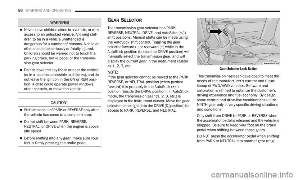
Gear Selector Lock Button
This transmission has been developed to meet the
needs
of the manufacturer’s current and future
lineup of FWD/AWD vehicles. Software and
calibration is refined to optimize the customer’s
driving experience and fuel economy. By design,
some vehicle and drive-line combinations utilize
NINTH gear only in very specific driving situations
and conditions.
Only shift from DRIVE to PARK or REVERSE when
the a c
celerator pedal is released and the vehicle is
stopped. Be sure to keep your foot on the brake
pedal when shifting between these gears.
DO NOT press the accelerator pedal when shifting
from PA
RK or NEUTRAL into another gear range.
Never leave children alone in a vehicle, or with
access to an unlocked vehicle. Allowing chil -
dren to be in a vehicle unattended is
d anger
ous for a number of reasons. A child or
others could be seriously or fatally injured.
Children should be warned not to touch the
parking brake, brake pedal or the transmis -
sion gear selector.
Do not leave the key fob in or near the vehicle
(or in a location accessible to children), and do
not leave the ignition in the ON or RUN posi -
tion. A child could operate power windows,
other c
ontrols, or move the vehicle.
CAUTION!
Shift into or out of PARK or REVERSE only after
the vehicle has come to a complete stop.
Do not shift between PARK, REVERSE,
NEUTRAL, or DRIVE when the engine is above
idle speed.
Before shifting into any gear, make sure your
foot is firmly pressing the brake pedal.
WARNING!
Page 90 of 364
88 STARTING AND OPERATING
The following indicators should be used to ensure
that you have properly engaged the transmission
into the PARK position:
When shifting into PARK, press the lock button
on the gear selector, and firmly move the gear
selector all the way forward until it stops and is
fully seated.
Look at the transmission gear position display
and verify that it indicates the PARK position (P),
and is not blinking.
With the brake pedal released, verify that the
gear selector will not move out of PARK.
REVERSE (R)
This range is for moving the vehicle backward.
Shift
into REVERSE only after the vehicle has come
to a complete stop.
NEUTRAL (N)
Use this range when the vehicle is standing for
p rolonge
d periods with the engine running. The
engine may be started in this range. Apply the
Electric Park Brake and shift the transmission into
PARK if you must exit the vehicle. DRIVE (D)
This range should be used for most city and
highwa
y driving. It provides the smoothest upshifts
and downshifts, and the best fuel economy. The
transmission automatically upshifts through all
forward gears.
When frequent transmission shifting occurs (such
as wh e
n operating the vehicle under heavy loading
conditions, in hilly terrain, traveling into strong
head winds or while towing a heavy trailer), use the
AutoStick shift control to select a lower gear. Under
Never leave children alone in a vehicle, or with
access to an unlocked vehicle. Allowing chil -
dren to be in a vehicle unattended is
d anger
ous for a number of reasons. A child or
others could be seriously or fatally injured.
Children should be warned not to touch the
parking brake, brake pedal or the transmis -
sion gear selector.
Do not leave the key fob in or near the vehicle
(or in a location accessible to children), and do
not leave the ignition in the ON/RUN position.
A child could operate power windows, other
controls, or move the vehicle.
CAUTION!
Before moving the transmission gear selector
out of PARK, you must turn the ignition to the
ON/RUN position, and also press the brake
pedal. Otherwise, damage to the gear selector
could result.
DO NOT race the engine when shifting from
PARK or NEUTRAL into another gear range, as
this can damage the drivetrain.
WARNING!WARNING!
Do not coast in NEUTRAL and never turn off the
ignition to coast down a hill. These are unsafe
practices that limit your response to changing
traffic or road conditions. You might lose control
of the vehicle and have a collision.
CAUTION!
Towing the vehicle, coasting, or driving for any
other reason with the transmission in NEUTRAL
can cause severe transmission damage.
For Recreational Towing Ú page 129.
For Towing A Disabled Vehicle Ú page 283.
Page 165 of 364
MULTIMEDIA 163
AUX MODE
Overview
Auxiliary Mode (AUX) is entered by inserting an AUX
device
using a cable with a 3.5 mm audio jack into
t h
e
A U
X port, or by pressing the AUX button on the
left side of the touchscreen, or under the Source
Select button (if equipped).
To insert an Auxiliary device, gently insert the
Auxili
ary device cable into the AUX port. If you
insert an Auxiliary device with the ignition and the
radio on, the unit will switch to AUX Mode and
begin to play.
Controlling The Auxiliary Device
The control of the Auxiliary device (e.g., selecting
p layl i
sts, play, fast forward, etc.) cannot be
provided by the radio; use the device controls
instead. Adjust the volume with the Volume button,
VOLUME/MUTE rotary knob, or the On/Off rotary
knob, or with the volume of the attached device.
NOTE:
The radio unit is acting as the amplifier for audio
output
from the Auxiliary device. Therefore, if the
volume control on the Auxiliary device is set too
low, there will be insufficient audio signal for the
radio unit to play the music on the device. Seek Up
/Seek Down
In USB Mode, press the Seek Up button on the
t ouchs c
reen for the next selection on the USB
device. Press and release the Seek Down button
on the touchscreen to return to the beginning of
the current selection, or to return to the beginning
of the previous selection if the USB device is within
the first three seconds of the current selection.
In Bluetooth® Mode, press and release the Seek
Up bu t
ton on the touchscreen for the next
selection on the Bluetooth® device. Press and
release the Seek Down button on the touchscreen
to return to the beginning of the current selection,
or return to the beginning of the previous selection
if the Bluetooth® device is within the first second
of the current selection.
Browse
In USB Mode, press the Browse button on the
touchs c
reen to display the browse window. In USB
Mode, the left side of the browse window displays
a list of ways you can browse through the contents
of the USB device. If supported by the device, you
can browse by Folder, Artist, Playlist, Album, Song,
etc. Press the desired button on the touchscreen
on the left side of the screen. The center of the
browse window shows items and their
sub-functions, which can be scrolled through by
pressing the Up and Down buttons to the right. The
TUNE/SCROLL knob can also be used to scroll. Media Mode
In USB Mode, press the Media button on the
touchs
c
reen to select the desired audio source:
USB.
In Bluetooth® Mode, press the Media button on
the t ou
chscreen to select the desired audio
source: Bluetooth®.
In AUX Mode, press the Media button on the
touchs c
reen to select the desired audio source:
AUX.
Repeat
In USB Mode, press the Repeat button on the
t ouchsc
reen to toggle the repeat functionality. The
Repeat button on the touchscreen is highlighted
when active. The Radio will continue to play the
current track, repeatedly, as long as the repeat is
active. Press the Repeat button again to enter
Repeat All. The radio will continue to play all the
current tracks, repeatedly, as long as the repeat
function is active. To cancel Repeat, press the
Repeat button a third time.
Shuffle
In USB Mode, press the Shuffle button on the
touchs c
reen to play the selections on the USB
device in random order to provide an interesting
change of pace. Press the Shuffle button on the
touchscreen a second time to turn this feature off.
5
Page 174 of 364
172 MULTIMEDIA
MAKING A SECOND CALL WHILE CURRENT
CALL IS IN PROGRESS
You can place a call on hold by pressing the Hold
button on the Phone main screen, then dial a
number from the keypad (if supported by your
mobile phone), recent calls, SMS Inbox or from the
phonebooks.
TOGGLING BETWEEN CALLS
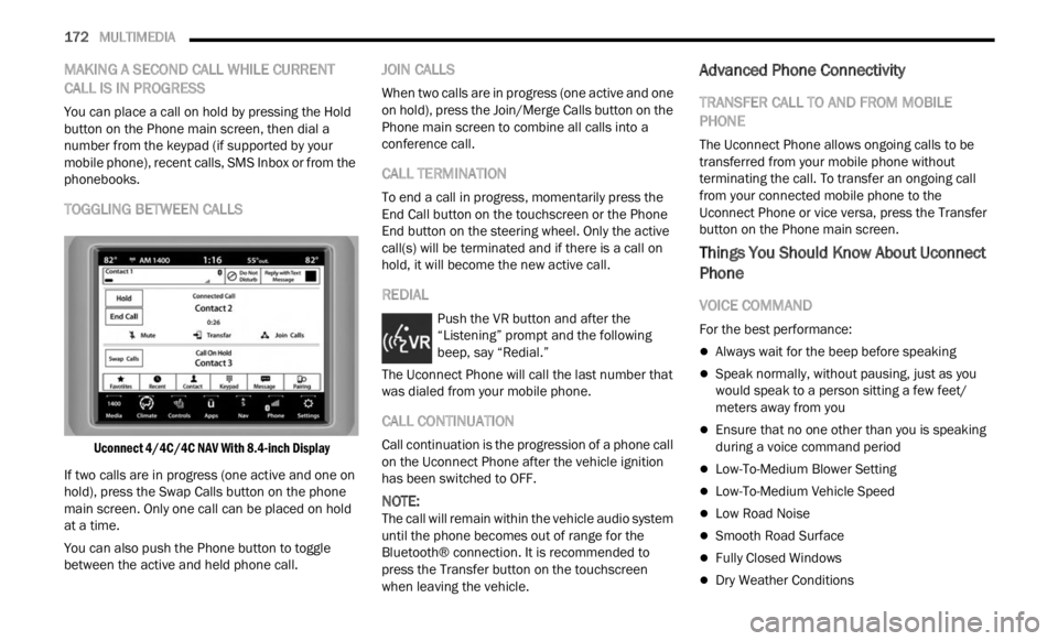
Uconnect 4/4C/4C NAV With 8.4-inch Display
If two calls are in progress (one active and one on
hold),
press the Swap Calls button on the phone
main screen. Only one call can be placed on hold
at a time.
You can also push the Phone button to toggle
betwee
n the active and held phone call.
JOIN CALLS
When two calls are in progress (one active and one
on hold), press the Join/Merge Calls button on the
Phone main screen to combine all calls into a
conference call.
CALL TERMINATION
To end a call in progress, momentarily press the
End Call button on the touchscreen or the Phone
End button on the steering wheel. Only the active
call(s) will be terminated and if there is a call on
hold, it will become the new active call.
REDIAL
Push the VR button and after the
“Listening” prompt and the following
bee
p,
say “Redial.”
The Uconnect Phone will call the last number that
was di
aled from your mobile phone.
CALL CONTINUATION
Call continuation is the progression of a phone call
on the Uconnect Phone after the vehicle ignition
has been switched to OFF.
NOTE:
The call will remain within the vehicle audio system
until
the phone becomes out of range for the
Bluetooth® connection. It is recommended to
press the Transfer button on the touchscreen
when leaving the vehicle.
Advanced Phone Connectivity
TRANSFER CALL TO AND FROM MOBILE
PHONE
The Uconnect Phone allows ongoing calls to be
transferred from your mobile phone without
terminating the call. To transfer an ongoing call
from your connected mobile phone to the
Uconnect Phone or vice versa, press the Transfer
button on the Phone main screen.
Things You Should Know About Uconnect
Phone
VOICE COMMAND
For the best performance:
Always wait for the beep before speaking
Speak normally, without pausing, just as you
would speak to a person sitting a few feet/
meters away from you
Ensure that no one other than you is speaking
during a voice command period
Low-To-Medium Blower Setting
Low-To-Medium Vehicle Speed
Low Road Noise
Smooth Road Surface
Fully Closed Windows
Dry Weather Conditions
Page 175 of 364
MULTIMEDIA 173
Even though the system is designed for many
languages and accents, the system may not always
work for some.
NOTE:
It is recommended that you do not store names in
your F a
vorites phonebook while the vehicle is in
motion.
Number and name recognition rate is optimized
when t
he entries are not similar. You can say “O”
(letter “O”) for “0” (zero).
Even though international dialing for most number
combin a
tions is supported, some shortcut dialing
number combinations may not be supported.
Audio Performance
Audio quality is maximized under:
Low-To-Medium Blower Setting
Low-To-Medium Vehicle Speed
Low Road Noise
Smooth Road Surface
Fully Closed Windows
Dry Weather Conditions
Operation From The Driver's Seat
Performance such as audio clarity, echo, and
loudne s
s to a large degree rely on the phone and
network, and not the Uconnect Phone.
Echo at the far end can sometimes be reduced by
loweri n
g the in-vehicle audio volume.
PHONE VOICE COMMANDS
Making and answering hands-free phone calls is
easy with Uconnect. When the Phonebook button
is illuminated on your touchscreen, your system is
ready. Check UconnectPhone.com for mobile
phone compatibility and pairing instructions.
Push the Phone button and wait for the beep to
say a command. See the following examples:
“ Call John Smith”
“Dial 123 456 7890”
“Redial ” (call previous outgoing phone number)
“Call back ” (call previously answered incoming
phone number)
Did You Know: When
providing a Voice Command,
push the Phone button and say “Call”, th en
pronounce the name exactl y as it appears in your phonebook. When a contact has multiple phone
numbers, you can say “
Call John Smith work”.
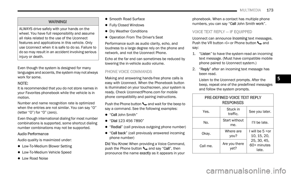
VOICE TEXT REPLY — IF EQUIPPED
Uconnect can announce incoming text messages.
Push the VR button or Phone button and
say:
1. “
Listen
” to have the system read an incoming
te x
t message. (Must have compatible mobile
phone paired to Uconnect system.)
2. “ Reply ” after an incoming text message has
bee n
read.
Listen to the Uconnect prompts. After the
beep,
repeat one of the predefined messages
and follow the system prompts.
WARNING!
ALWAYS drive safely with your hands on the
wheel. You have full responsibility and assume
all risks related to the use of the Uconnect
features and applications in this vehicle. Only
use Uconnect when it is safe to do so. Failure to
do so may result in an accident involving serious
injury or death.
PRE-DEFINED VOICE TEXT REPLY
RESPONSES
Yes. Stuck in
traff i
c. See you later.
No. Start without
me. I’l
l
be late.
Okay. Where are
you? I w
i
ll be 5
25, 30, 45,
60> minutes late.
Call me.
Are you there
yet?
5
Page 239 of 364
SAFETY 237
NOTE:
It is particularly important for you to check the tire
press u
re in all of the tires on your vehicle monthly
and to maintain the proper pressure.
The TPMS consists of the following components:
Receiver module
Four Tire Pressure Monitoring System sensors
Tire Pressure Monitoring System Light
TIRE PRESSURE MONITORING SYSTEM LOW
PRESSURE WARNINGS
The Tire Pressure Monitoring System
Light will illuminate in the instrument
clust e
r, a “LOW TIRE PRESSURE”
message will display in the instrument
cluster, an "Inflate to XX" message will be displayed
and a chime will sound when tire pressure is low in
one or more of the four active road tires. Should
this occur, you should stop as soon as possible,
check the inflation pressure of each tire on your
vehicle, and inflate each tire to the vehicle’s
recommended cold placard pressure value as
shown in the "Inflate to XX" message. Once the
system receives the updated tire pressures, the
system will automatically update and the Tire
Pressure Monitoring System Light will turn off.
NOTE:
When filling warm tires, the tire pressure may need
to be i
ncreased up to an additional 4 psi (28 kPa)
above the recommended cold placard pressure in
order to turn the Tire Pressure Monitoring System
Light off. The vehicle may need to be driven for up
to 20 minutes above 15 mph (24 km/h) in order
for th e
TPMS to receive this information.
SERVICE TPMS WARNING
When a system fault is detected, the Tire Pressure
Monitoring System Light will flash on and off for
75 seconds and then remain on solid. The system
fault
will also sound a chime. If the ignition is
cycled, this sequence will repeat, providing the
system fault still exists. The Tire Pressure
Monitoring System Light will turn off when the fault
condition no longer exists. A system fault can occur
due to any of the following:
Jamming due to electronic devices or driving
next to facilities emitting the same radio
frequencies as the TPMS sensors.
Installing some form of aftermarket window
tinting that affects radio wave signals.
Lots of snow or ice around the wheels or wheel
housings.
Using tire chains on the vehicle.
Using wheels/tires not equipped with TPMS
sensors. Vehicles With Compact Spare Or Non-Matching
Full
S
ize Spare
1. The compact spare tire or non-matching full size
spare tire does not have a Tire Pressure
Monitoring System sensor. Therefore, the
TPMS will not monitor the pressure in the
spare tire.
2. If you install the compact or non-matching full size
spare tire in place of a road tire that has a
pressure below the low-pressure warning limit, a
chime will sound and the TPMS Light and “LOW
TIRE PRESSURE” and "Inflate to XX" messages
will turn on upon the next ignition cycle.
3. After driving the vehicle for up to 20 minu
tes
above 1
5 mph (24 km/h), the TPMS Light will
flash
on and off for 75 seconds and then
remain on solid.
4. For each subsequent ignition cycle, a chime will
sound and the TPMS Light will flash on and
off for 75 seconds and then remain on solid.
5. Once you repair or replace the original road tire and r
einstall it on the vehicle in place of the
compact spare or non-matching full size spare,
the TPMS will update automatically and the
“TPMS Light” will turn off, as long as no tire
pressure is below the low-pressure warning
limit in any of the four active road tires. The
vehicle may need to be driven for up to
20 minutes above 15 mph (24 km/h) in order
for th e
TPMS to receive this information.
6
Page 240 of 364
238 SAFETY
Tire Pressure Monitoring System
Operation
TPMS uses wireless technology with wheel rim
mounted electronic sensors to monitor tire
pressure levels. Sensors, mounted to each wheel
as part of the valve stem, transmit tire pressure
readings to the receiver module.
NOTE:
It is particularly important for you to check the tire
press u
re in all of the tires on your vehicle monthly
and to maintain the proper pressure.
The TPMS consists of the following components:
Receiver module
Four Tire Pressure Monitoring System sensors
Various Tire Pressure Monitoring System
messages, which display in the instrument
cluster
Tire Pressure Monitoring System Light
TIRE PRESSURE MONITORING SYSTEM LOW
PRESSURE WARNINGS
The Tire Pressure Monitoring System
Light will illuminate in the instrument
c lu
st
e
r and a chime will sound when tire
pressure is low in one or more of the four
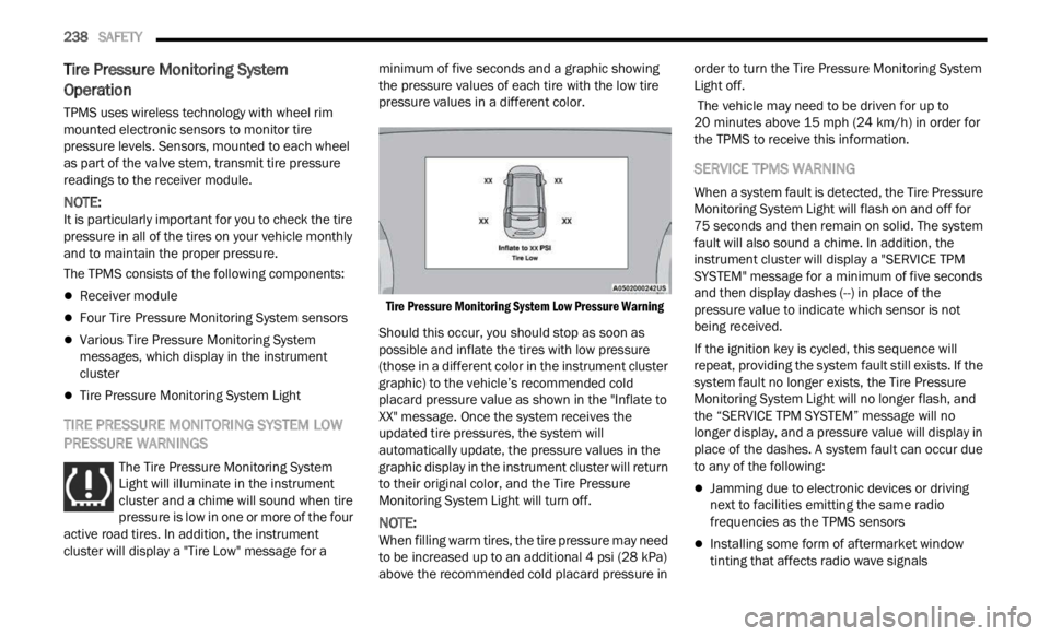
active road tires. In addition, the instrument
cluster will display a "Tire Low" message for a minimum of five seconds and a graphic showing
the pressure values of each tire with the low tire
pressure values in a different color.
Tire Pressure Monitoring System Low Pressure Warning
Should this occur, you should stop as soon as
possibl
e and inflate the tires with low pressure
(those in a different color in the instrument cluster
graphic) to the vehicle’s recommended cold
placard pressure value as shown in the "Inflate to
XX" message. Once the system receives the
updated tire pressures, the system will
automatically update, the pressure values in the
graphic display in the instrument cluster will return
to their original color, and the Tire Pressure
Monitoring System Light will turn off.
NOTE:
When filling warm tires, the tire pressure may need
to be i
ncreased up to an additional 4 psi (28 kPa)
above the recommended cold placard pressure in order to turn the Tire Pressure Monitoring System
Light off.
The vehicle may need to be driven for up to
20
min u
tes above 15 mph (24 km/h) in order for
t h
e
T P
MS to receive this information.
SERVICE TPMS WARNING
When a system fault is detected, the Tire Pressure
Monitoring System Light will flash on and off for
75 seconds and then remain on solid. The system
f ault
will also sound a chime. In addition, the
instrument cluster will display a "SERVICE TPM
SYSTEM" message for a minimum of five seconds
and then display dashes (--) in place of the
pressure value to indicate which sensor is not
being received.
If the ignition key is cycled, this sequence will
repea t
, providing the system fault still exists. If the
system fault no longer exists, the Tire Pressure
Monitoring System Light will no longer flash, and
the “SERVICE TPM SYSTEM” message will no
longer display, and a pressure value will display in
place of the dashes. A system fault can occur due
to any of the following:
Jamming due to electronic devices or driving
next to facilities emitting the same radio
frequencies as the TPMS sensors
Installing some form of aftermarket window
tinting that affects radio wave signals
Page 242 of 364
240 SAFETY
display the “SERVICE TPM SYSTEM” message in
the instrument cluster display but dashes (--) will
remain in place of the pressure values.
To reactivate the TPMS, replace all four wheel and
tire a
ssemblies (road tires) with tires equipped with
TPMS sensors. Then, drive the vehicle for up to
20 minutes above 15 mph (24 km/h). The TPMS
will c
hime, the TPMS Light will flash on and off for
75 seconds and then turn off, and the instrument
cluster will display the “SERVICE TPM SYSTEM”
message. The instrument cluster will also display
pressure values in place of the dashes. On the next
ignition switch cycle the “SERVICE TPM SYSTEM”
message will no longer be displayed as long as no
system fault exists.
OCCUPANT RESTRAINT SYSTEMS
Some of the most important safety features in your
vehicle are the restraint systems:
OCCUPANT RESTRAINT SYSTEMS
Seat Belt Systems
Supplemental Restraint Systems (SRS) Air Bags
Child Restraints
Some of the safety features described in this
secti on
may be standard equipment on some
models, or may be optional equipment on others. If
you are not sure, ask an authorized dealer.
IMPORTANT SAFETY PRECAUTIONS
Please pay close attention to the information in
this section. It tells you how to use your restraint
system properly, to keep you and your passengers
as safe as possible.
Here are some simple steps you can take to
minimi
ze the risk of harm from a deploying air bag:
1. Children 12 years old and under should alway
s ride buckled up in the rear seat of a
vehicle with a rear seat.
2. A child who is not big enough to wear the vehi c
le seat belt properly must be secured in
the appropriate child restraint or
belt-positioning booster seat in a rear seating
position Ú page 255.
3. If a child from 2 to 12 years old (not in a rear-
facing child restraint) must ride in the
front passenger seat, move the seat as far
back as possible and use the proper child
restraint Ú page 255.
4. Never allow children to slide the shoulder belt behi n
d them or under their arm.
5. You should read the instructions provided with your c
hild restraint to make sure that you are
using it properly.
6. All occupants should always wear their lap and shoul d
er belts properly. 7. The driver and front passenger seats should
be m ov
ed back as far as practical to allow the
front air bags room to inflate.
8. Do not lean against the door or window. If your vehi c
le has side air bags, and deployment
occurs, the side air bags will inflate forcefully
into the space between occupants and the
door and occupants could be injured.
9. If the air bag system in this vehicle needs to be modif i
ed to accommodate a disabled person,
see Ú page 346 for customer service contact
information.
WARNING!
Never place a rear-facing child restraint in
front of an air bag. A deploying passenger
front air bag can cause death or serious injury
to a child 12 years or younger, including a
child in a rear-facing child restraint.
Never install a rear-facing child restraint in the
front seat of a vehicle. Only use a rear-facing
child restraint in the rear seat. If the vehicle
does not have a rear seat, do not transport a
rear-facing child restraint in that vehicle.
Page 252 of 364
250 SAFETY
Supplemental Side Air Bag Inflatable Curtains
(SABICs)
This vehicle is equipped with Supplemental Side
Air Ba
g Inflatable Curtains (SABICs).
Supplemental Side Air Bag Inflatable Curtains
(SABIC
s) are located above the side windows. The
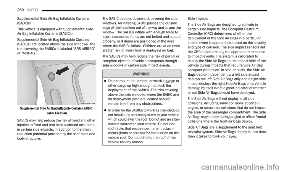
trim covering the SABICs is labeled “SRS AIRBAG”
or “AIRBAG.”
Supplemental Side Air Bag Inflatable Curtain (SABIC) Label
Location
SABICs may help reduce the risk of head and other
injuri
es to front and rear seat outboard occupants
in certain side impacts, in addition to the injury
reduction potential provided by the seat belts and
body structure. The SABIC deploys downward, covering the side
window
s
. An inflating SABIC pushes the outside
edge of the headliner out of the way and covers the
window. The SABICs inflate with enough force to
injure occupants if they are not belted and seated
properly, or if items are positioned in the area
where the SABICs inflate. Children are at an even
greater risk of injury from a deploying air bag.
The SABICs may help reduce the risk of partial or
comple t
e ejection of vehicle occupants through
side windows in certain side impact events. Side Impacts
The Side Air Bags are designed to activate in
c
erta i
n side impacts. The Occupant Restraint
Controller (ORC) determines whether the
deployment of the Side Air Bags in a particular
impact event is appropriate, based on the severity
and type of collision. The side impact sensors aid
the ORC in determining the appropriate response
to impact events. The system is calibrated to
deploy the Side Air Bags on the impact side of the
vehicle during impacts that require Side Air Bag
occupant protection. In side impacts, the Side Air
Bags deploy independently; a left side impact
deploys the left Side Air Bags only and a right-side
impact deploys the right Side Air Bags only. Vehicle
damage by itself is not a good indicator of whether
or not Side Air Bags should have deployed.
The Side Air Bags will not deploy in all side
collis i
ons, including some collisions at certain
angles, or some side collisions that do not impact
the area of the passenger compartment. The Side
Air Bags may deploy during angled or offset frontal
collisions where the front air bags deploy.
Side Air Bags are a supplement to the seat belt
restr a
int system. Side Air Bags deploy in less time
than it takes to blink your eyes.
WARNING!
Do not mount equipment, or stack luggage or
other cargo up high enough to block the
deployment of the SABICs. The trim covering
above the side windows where the SABIC and
its deployment path are located should
remain free from any obstructions.
In order for the SABICs to work as intended, do
not install any accessory items in your vehicle
which could alter the roof. Do not add an after -
market sunroof to your vehicle. Do not add
roof r a
cks that require permanent attach -
ments (bolts or screws) for installation on the
v ehicl
e roof. Do not drill into the roof of the
vehicle for any reason.