stop start JEEP RENEGADE 2023 Workshop Manual
[x] Cancel search | Manufacturer: JEEP, Model Year: 2023, Model line: RENEGADE, Model: JEEP RENEGADE 2023Pages: 364, PDF Size: 18.65 MB
Page 229 of 364
SAFETY 227
Hill Start Assist (HSA)
HSA is designed to help the driver accelerate the
vehicle from a complete stop while on an incline. If
the driver releases the brake while stopped on an
incline, HSA will continue to hold the brake
pressure for a short period. If the driver does not
apply the throttle before this time expires, the
system will release brake pressure and the vehicle
will roll down the hill as normal. The system will
release brake pressure in proportion to amount of
throttle applied.
The following conditions must be met in order for
HSA to a
ctivate:
The vehicle must be stopped.
The vehicle must be on a 5% (approximate)
grade or greater hill.
The gear selection must match vehicle uphill
direction (i.e., vehicle facing uphill is in forward
gear; vehicle backing uphill is in REVERSE gear).
For vehicles equipped with an automatic trans -
mission, the HSA will work in REVERSE gear and all f
or ward gears. The system will not activate if
the transmission is in PARK.
Disabling And Enabling HSA
This feature can be turned on or turned off. To
chang e
the current setting, see Ú page 64.
Traction Control System (TCS)
TCS monitors the amount of wheel spin of each of
the driven wheels. If wheel spin is detected, brake
pressure is applied to the slipping wheel(s) and
engine power is reduced to provide enhanced
acceleration and stability. A feature of the TCS,
Brake Limited Differential (BLD) functions similarly to a limited slip differential and controls the wheel
spin across a driven axle. If one wheel on a driven
axle is spinning faster than the other, the system
will apply the brake of the spinning wheel. This will
allow more engine torque to be applied to the
wheel that is not spinning. This feature remains
active even if TCS and Electronic Stability Control
(ESC) are in the “Partial Off” mode or the “Full Off”
modes. For further information, see
Ú page 223.
Trailer Sway Control (TSC) — If Equipped
TSC uses sensors in the vehicle to recognize an
excessively swaying trailer and will take the
appropriate actions to attempt to stop the sway.
The system may reduce engine power and apply
the brake of the appropriate wheel(s) to counteract
the sway of the trailer.
NOTE:
TSC cannot stop all trailers from swaying. Always
use c a
ution when towing a trailer and follow the
trailer tongue weight recommendations. For
further information, see Ú page 124. When TSC is
functioning, the ESC Activation/Malfunction Indi -
cator Light will flash, the engine power may be
r educ e
d and you may feel the brakes being applied
to individual wheels to attempt to stop the trailer
from swaying. TSC is disabled when the ESC
system is in the “Partial Off” mode.
WARNING!
HDC is only intended to assist the driver in
controlling vehicle speed when descending hills.
The driver must remain attentive to the driving
conditions and is responsible for maintaining a
safe vehicle speed.WARNING!
There may be situations where the Hill Start
Assist (HSA) will not activate and slight rolling
may occur, such as on minor hills or with a
loaded vehicle, or while pulling a trailer. HSA is
not a substitute for active driving involvement. It
is always the driver’s responsibility to be
attentive to distance to other vehicles, people,
and objects, and most importantly brake
operation to ensure safe operation of the vehicle
under all road conditions. Your complete
attention is always required while driving to
maintain safe control of your vehicle. Failure to
follow these warnings can result in a collision or
serious personal injury.
6
Page 230 of 364
228 SAFETY
AUXILIARY DRIVING SYSTEMS
BLIND SPOT MONITORING (BSM) —
I
F EQUIPPED
BSM uses two radar-based sensors, located inside
the rear fascia/bumper to detect highway
licensable vehicles (automobiles, trucks,
motorcycles, etc.) that enter the blind spot zones
from the rear/front/side of the vehicle.
Rear Detection Zones
When the vehicle is started, the BSM Warning Light
will m
omentarily illuminate in both outside rearview mirrors to let the driver know that the
system is operational. The BSM system sensors
operate when the vehicle is in any forward gear
and enters standby mode when the vehicle is in
PARK (P).
The BSM detection zone covers approximately one
lane
w
idth on both sides of the vehicle, 10 ft (3 m).
The z on
e length starts at the outside mirror and
extends approximately 20 ft (6 m) beyond the rear
fascia
/bumper of the vehicle. The BSM system
monitors the detection zones on both sides of the
vehicle when the vehicle speed reaches
approximately 6 mph (10 km/h) or higher and will
alert
the driver of vehicles in these areas.
NOTE:
The BSM system DOES NOT alert the driver
about rapidly approaching vehicles that are
outside the detection zones.
If a trailer is connected to the vehicle, it is neces -
sary to deactivate the BSM system manually
t h r
ou g
h
the settings menu to avoid a misdetec -
tion. For further information, see Ú page 133.
The area on the rear fascia/bumper where the
r adar
sensors are located must remain free of
snow, ice, and dirt/road contamination so that the
BSM system can function properly. Do not block
the radar sensors located on the rear fascia/
bumper with foreign objects (bumper stickers,
bicycle racks, etc.).
Rear Sensor Locations
The BSM system notifies the driver of objects in the
detec t
ion zones by illuminating the BSM warning
light located in the outside mirrors in addition to
sounding an audible (chime) alert and reducing the
radio volume Ú page 231.
BSM Warning Light
WARNING!
If TSC activates while driving, slow the vehicle
down, stop at the nearest safe location, and
adjust the trailer load to eliminate trailer sway.
Page 243 of 364
SAFETY 241
SEAT BELT SYSTEMS
Buckle up even though you are an excellent driver,
even on short trips. Someone on the road may be
a poor driver and could cause a collision that
includes you. This can happen far away from home
or on your own street.
Research has shown that seat belts save lives, and
they c
an reduce the seriousness of injuries in a
collision. Some of the worst injuries happen when
people are thrown from the vehicle. Seat belts
reduce the possibility of ejection and the risk of
injury caused by striking the inside of the vehicle.
Everyone in a motor vehicle should be belted at all
times.
Enhanced Seat Belt Use Reminder System
(BeltAlert)
Driver And Passenger BeltAlert — If Equipped
BeltAlert is a feature intended to remind the driver and outboard front seat
passenger to buckle their seat belts. The
BeltAlert feature is active whenever the
ignition switch is in the START or ON/RUN position.
Initial Indication
If the driver is unbuckled when the ignition switch
is fi r
st in the START or ON/RUN position a chime
will signal for a few seconds. If the driver or
outboard front seat passenger is unbuckled when
the ignition switch is first in the START or ON/RUN position the Seat Belt Reminder Light will turn solid
red and remain red until the seat belt is buckled.
After the driver and outboard front seat passenger
have buckled their seat belts all Seat Belt
Reminder Lights will turn off. The outboard front
passenger seat BeltAlert is not active when the
outboard front passenger seat is unoccupied. The
cluster display will inform the driver that you must
fasten the driver’s seat belt in order to release the
parking brake.
BeltAlert Warning Sequence
The BeltAlert warning sequence is activated when
t
he v e
hicle is moving above a specified vehicle
speed range and the driver or outboard front seat
passenger is unbuckled (the outboard front
passenger seat BeltAlert is not active when the
outboard front passenger seat is unoccupied). The
BeltAlert warning sequence starts by blinking the
Seat Belt Reminder Light and sounding an
intermittent chime. Once the BeltAlert warning
sequence has completed, the Seat Belt Reminder
Light will remain solid red until the driver and
outboard front seat passenger are buckled. The
BeltAlert warning sequence may repeat based on
vehicle speed until the driver and occupied
outboard front seat passenger seat belts are
buckled. The driver should instruct all occupants to
buckle their seat belts. Change Of Status
If the driver or outboard front seat passenger
unbuc
k
les their seat belt while the vehicle is
traveling, the BeltAlert warning sequence will begin
until the seat belts are buckled again.
The outboard front passenger seat BeltAlert is not
active
when the outboard front passenger seat is
unoccupied. BeltAlert may be triggered when an
animal or other items are placed on the outboard
front passenger seat or when the seat is folded flat
(if equipped). It is recommended that pets be
restrained in the rear seat (if equipped) in pet
harnesses or pet carriers that are secured by seat
belts, and cargo is properly stowed.
BeltAlert can be activated or deactivated by an
author i
zed dealer. FCA US LLC does not
recommend deactivating BeltAlert.
NOTE:
If BeltAlert has been deactivated, the Seat Belt
Remin d
er Light will turn on and remain on until the
driver and outboard front seat passenger seat
belts are buckled.
Lap/Shoulder Belts
All seating positions in your vehicle are equipped
with lap/shoulder belts.
The seat belt webbing retractor will lock only during
very s
udden stops or collisions. This feature allows
the shoulder part of the seat belt to move freely
with you under normal conditions. However, in a
6
Page 248 of 364
246 SAFETY
How To Engage The Automatic Locking Mode
1. Buckle the combination lap and shoulder
belt.
2
. Grab the shoulder portion and pull downward until
the entire seat belt is extracted.
3. Allow the seat belt to retract. As the seat belt retra
cts, you will hear a clicking sound. This
indicates the seat belt is now in the Automatic
Locking Mode.
How To Disengage The Automatic Locking Mode
Unbuckle the combination lap/shoulder belt and
allow i
t to retract completely to disengage the
Automatic Locking Mode and activate the vehicle
sensitive (emergency) locking mode.
SUPPLEMENTAL RESTRAINT SYSTEMS
(SRS)
Some of the safety features described in this
section may be standard equipment on some
models, or may be optional equipment on others. If
you are not sure, ask an authorized dealer.
The air bag system must be ready to protect you in
a colli
sion. The Occupant Restraint Controller
(ORC) monitors the internal circuits and
interconnecting wiring associated with the electrical Air Bag System Components. Your
vehicle may be equipped with the following Air Bag
System Components:
Air Bag System Components
Occupant Restraint Controller (ORC)
Air Bag Warning Light
Steering Wheel and Column
Instrument Panel
Knee Impact Bolsters
Driver and Front Passenger Air Bags
Seat Belt Buckle Switch
Supplemental Side Air Bags
Supplemental Knee Air Bags
Front and Side Impact Sensors
Seat Belt Pretensioners
Seat Track Position Sensors
Air Bag Warning Light
The Occupant Restraint Controller (ORC)
monitors the readiness of the electronic
parts
of the air bag system whenever the
ignition switch is in the AVV/START or
MAR/ACC/ON/RUN position. If the ignition switch
is in the STOP/OFF/LOCK position the air bag
system is not on and the air bags will not inflate.
WARNING!
Never place a rear-facing child restraint in
front of an air bag. A deploying passenger
front air bag can cause death or serious injury
to a child 12 years or younger, including a
child in a rear-facing child restraint.
Never install a rear-facing child restraint in the
front seat of a vehicle. Only use a rear-facing
child restraint in the rear seat. If the vehicle
does not have a rear seat, do not transport a
rear-facing child restraint in that vehicle.
WARNING!
The seat belt assembly must be replaced if the
switchable Automatic Locking Retractor (ALR)
feature or any other seat belt function is not
working properly when checked according to
the procedures in the Service Manual.
Failure to replace the seat belt assembly
could increase the risk of injury in collisions.
Do not use the Automatic Locking Mode to
restrain occupants who are wearing the seat
belt or children who are using booster seats.
The locked mode is only used to install
rear-facing or forward-facing child restraints
that have a harness for restraining the child.
Page 255 of 364

SAFETY 253
NOTE:
After an accident, remember to cycle the ignition to
the S T
OP (OFF/LOCK) position and remove the key
from the ignition switch to avoid draining the
battery. Carefully check the vehicle for fuel leaks in
the engine compartment and on the ground near
the engine compartment and fuel tank before
resetting the system and starting the engine. If
there are no fuel leaks or damage to the vehicle
electrical devices (e.g. headlights) after an
accident, reset the system by following the procedure described below. If you have any doubt,
contact an authorized dealer.
Enhanced Accident Response System
Reset Procedure
After the event occurs, when the system is active,
a message regarding fuel cutoff is displayed. Turn
the ignition switch from ignition AVV/START or
MAR/ACC/ON/RUN to ignition STOP/OFF/LOCK.
Carefully check the vehicle for fuel leaks in the
engine compartment and on the ground near the
engine compartment and fuel tank before
resetting the system and starting the engine.
Depending on the nature of the event the left and
right
turn signal lights, located in the instrument
panel, may both be blinking and will continue to
blink. In order to move your vehicle to the side of
the road, you must follow the system reset
procedure.
Customer Action
NOTE:
Each step MUST BE held for at least two seconds.Customer Will See
1. Turn ignition STOP/OFF/LOCK. (Turn Signal Switch Must be placed in
Neutral State).
2. Turn ignition MAR/ACC/ON/RUN. Right turn light BLINKS.
Left turn light is OFF.
3. Turn right turn signal switch ON. Right turn light is ON SOLID.
Left turn light BLINKS.
4. Place turn signal in neutral state. Right turn light is OFF.
Left turn light BLINKS.
5. Turn left turn signal switch ON. Right turn light BLINKS.
Left turn light is ON SOLID.
6. Place turn signal in neutral state. Right turn light BLINKS.
Left turn light is OFF.6
Page 256 of 364

254 SAFETY
If a reset procedure step is not completed within 60 seconds, then the turn signal lights will blink and the reset procedure must be performed again in order to
be successful.7. Turn right turn signal switch ON.
Right turn light is ON SOLID.
Left turn light BLINKS.
8. Place turn signal in neutral state. Right turn light is OFF.
Left turn light BLINKS.
9. Turn left turn signal switch ON. Right turn light is ON SOLID.
Left turn light is ON SOLID.
10. Turn left turn signal switch OFF. (Turn Signal Switch Must be placed in
N eutr a
l State). Right turn light is OFF.
Left turn light is OFF.
11. Turn ignition STOP/OFF/LOCK.
12. Turn ignition MAR/ACC/ON/RUN. (Entire sequence needs to be completed
w ithin
one minute or sequence will need to be repeated). System is now reset and the engine may be started.
Turn hazard flashers OFF (Manually).
Customer Action
NOTE:
Each step MUST BE held for at least two seconds.Customer Will See
Page 272 of 364

270 IN CASE OF EMERGENCY
(Continued)
SOS Call System Limitations
Vehicles sold in Mexico DO NOT
have SOS Call
system capabilities.
SOS or other emergency line operators in Mexico
may not
answer or respond to SOS system calls.
NOTE:
The SOS Call function may not be available for the
first
minute after the vehicle is started
If the SOS Call system detects a malfunction, any
of the
following may occur at the time the
malfunction is detected, and at the beginning of
each ignition cycle:
The overhead console lights located within the
SOS and ASSIST buttons will continuously illumi -
nate red.
The Device Screen will display the following
message: “Vehicle device requires service.
Please contact an authorized dealer.”
An In-Vehicle Audio message will state “Vehicle
device requires service. Please contact an
authorized dealer.” Even if the SOS Call system is fully functional,
factor
s
beyond FCA US LLC’s control may prevent
or stop the SOS Call system operation. These
include, but are not limited to, the following
factors:
The ignition is in the OFF position.
The vehicle’s electrical systems are not intact.
The SOS Call system software and/or hardware
are damaged during a crash.
The vehicle battery loses power or becomes
disconnected during a vehicle crash.
LTE (voice/data) or 4G (data) network and/or
Global Positioning Satellite signals are unavail -
able or obstructed.
Equipment malfunction at the SOS operator
facility.
Operator error by the SOS operator.
Never place anything on or near the vehicle’s
operable network and GPS antennas. You
could prevent operable network and GPS
signal reception, which can prevent your
vehicle from placing an emergency call. An
operable network and GPS signal reception is
required for the SOS Call system to function
properly.
The SOS Call system is embedded into the
vehicle’s electrical system. Do not add after -
market electrical equipment to the vehicle’s
electr
ical system. This may prevent your
vehicle from sending a signal to initiate an
emergency call. To avoid interference that can
cause the SOS Call system to fail, never add
aftermarket equipment (e.g., two-way mobile
radio, CB radio, data recorder, etc.) to your
vehicle’s electrical system or modify the
antennas on your vehicle. IF YOUR VEHICLE
LOSES BATTERY POWER FOR ANY REASON
(INCLUDING DURING OR AFTER AN ACCI -
DENT), THE UCONNECT FEATURES, APPS AND
SERVI C
ES, AMONG OTHERS, WILL NOT
OPERATE.
Modifications to any part of the SOS Call
system could cause the air bag system to fail
when you need it. You could be injured if the
air bag system is not there to help protect you.
WARNING!
WARNING!
Ignoring the overhead console light could
mean you will not have SOS Call services. If
the overhead console light is illuminated, have
an authorized dealer service the SOS Call
system immediately.
The Occupant Restraint Control module turns
on the air bag Warning Light on the instrument
panel if a malfunction in any part of the
system is detected. If the Air Bag Warning
Light is illuminated, have an authorized dealer
service the Occupant Restraint Control system
immediately.
WARNING!
Page 275 of 364
IN CASE OF EMERGENCY 273
(Continued)
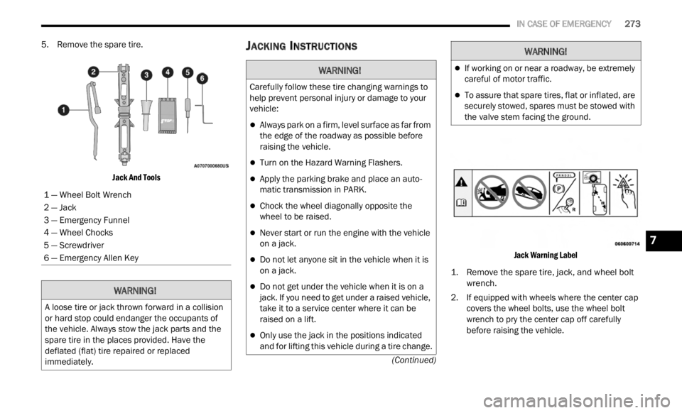
5. Remove the spare tire.
Jack And Tools
JACKING INSTRUCTIONS
Jack Warning Label
1. Remove the spare tire, jack, and wheel bolt wrench.
2
. If equipped with wheels where the center cap covers
the wheel bolts, use the wheel bolt
wrench to pry the center cap off carefully
before raising the vehicle.
1 — Wheel Bolt Wrench
2 — Jack
3 — Emergency Funnel
4 — Wheel Chocks
5 — Screwdriver
6 — Emergency Allen KeyWARNING!
A loose tire or jack thrown forward in a collision
or hard stop could endanger the occupants of
the vehicle. Always stow the jack parts and the
spare tire in the places provided. Have the
deflated (flat) tire repaired or replaced
immediately.
WARNING!
Carefully follow these tire changing warnings to
help prevent personal injury or damage to your
vehicle:
Always park on a firm, level surface as far from
the edge of the roadway as possible before
raising the vehicle.
Turn on the Hazard Warning Flashers.
Apply the parking brake and place an auto
-
matic transmission in PARK.
Chock the wheel diagonally opposite the
wheel to be raised.
Never start or run the engine with the vehicle
on a jack.
Do not let anyone sit in the vehicle when it is
on a jack.
Do not get under the vehicle when it is on a
jack. If you need to get under a raised vehicle,
take it to a service center where it can be
raised on a lift.
Only use the jack in the positions indicated
and for lifting this vehicle during a tire change.
If working on or near a roadway, be extremely
careful of motor traffic.
To assure that spare tires, flat or inflated, are
securely stowed, spares must be stowed with
the valve stem facing the ground.
WARNING!
7
Page 278 of 364
276 IN CASE OF EMERGENCY
TIRE SERVICE KIT — IF EQUIPPED
TIRE SERVICE KIT STORAGE
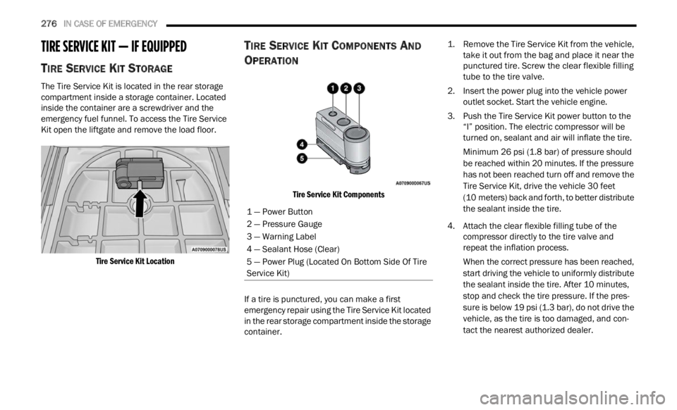
The Tire Service Kit is located in the rear storage
compartment inside a storage container. Located
inside the container are a screwdriver and the
emergency fuel funnel. To access the Tire Service
Kit open the liftgate and remove the load floor.
Tire Service Kit Location
TIRE SERVICE KIT COMPONENTS AND
O
PERATION
Tire Service Kit Components
If a tire is punctured, you can make a first
emerg e
ncy repair using the Tire Service Kit located
in the rear storage compartment inside the storage
container.
1. Remove the Tire Service Kit from the vehicle,
take
it out from the bag and place it near the
punctured tire. Screw the clear flexible filling
tube to the tire valve.
2. Insert the power plug into the vehicle power outlet
socket. Start the vehicle engine.
3. Push the Tire Service Kit power button to the “I” p
osition. The electric compressor will be
turned on, sealant and air will inflate the tire.
Minimum 26 psi (1.8 bar) of pressure should
be re a
ched within 20 minutes. If the pressure
has not
been reached turn off and remove the
Tire Service Kit, drive the vehicle 30 feet
(10 meters) back and forth, to better distribute
the se
alant inside the tire.
4. Attach the clear flexible filling tube of the compre
ssor directly to the tire valve and
repeat the inflation process.
When the correct pressure has been reached,
start
driving the vehicle to uniformly distribute
the sealant inside the tire. After 10 minutes,
stop an
d check the tire pressure. If the pres -
sure is below 19 psi (1.3 bar), do not drive the
vehicl
e, as the tire is too damaged, and con -
tact the nearest authorized dealer.
1 — Power Button
2 — Pressure Gauge
3 — Warning Label
4 — Sealant Hose (Clear)
5 — Power Plug (Located On Bottom Side Of Tire
Servic
e Kit)
Page 301 of 364
SERVICING AND MAINTENANCE 299
(Continued)
Under normal operating conditions, the catalytic
converter will not require maintenance. However, it
is important to keep the engine properly tuned to
ensure proper catalyst operation and prevent
possible catalyst damage.
NOTE:
Intentional tampering with emissions control
syste m
s can result in civil penalties being
assessed against you.
In unusual situations involving grossly
malfu n
ctioning engine operation, a scorching odor
may suggest severe and abnormal catalyst overheating. If this occurs, stop the vehicle, turn off
the engine and allow it to cool. Service, including a
tune-up to manufacturer's specifications, should
be obtained immediately.
To minimize the possibility of catalytic converter
damag
e
:
Do not interrupt the ignition when the transmis -
sion is in gear and the vehicle is in motion.
Do not try to start the vehicle by pushing or
towing the vehicle.
Do not idle the engine with any ignition compo -
nents disconnected or removed, such as when
diagn os
tic testing, or for prolonged periods
during very rough idle or malfunctioning oper -
ating conditions.
COOLING SYSTEM
Coolant Checks
Check engine coolant (antifreeze) protection every
12 months (before the onset of freezing weather,
where
applicable). If the engine coolant is dirty or
rusty in appearance, the system should be
drained, flushed and refilled with fresh engine
coolant. Check the front of the A/C condenser for
any accumulation of bugs, leaves, etc. If dirty,
clean by gently spraying water from a garden hose
vertically down the face of the condenser.
CAUTION!
The catalytic converter requires the use of
unleaded fuel only. Leaded gasoline will
destroy the effectiveness of the catalyst as an
emissions control device and may seriously
reduce engine performance and cause
serious damage to the engine.
Damage to the catalytic converter can result if
your vehicle is not kept in proper operating
condition. In the event of engine malfunction,
particularly involving engine misfire or other
apparent loss of performance, have your
vehicle serviced promptly. Continued operation
of your vehicle with a severe malfunction could
cause the converter to overheat, resulting in
possible damage to the converter and vehicle.
WARNING!
You or others can be badly burned by hot
engine coolant (antifreeze) or steam from your
radiator. If you see or hear steam coming from
under the hood, do not open the hood until the
radiator has had time to cool. Never open a
cooling system pressure cap when the radi -
ator or coolant bottle is hot.
Keep hands, tools, clothing, and jewelry away
from the radiator cooling fan when the hood is
raised. The fan starts automatically and may
start at any time, whether the engine is
running or not.
When working near the radiator cooling fan,
disconnect the fan motor lead or turn the igni -
tion to the OFF mode. The fan is temperature
c ontroll
ed and can start at any time the igni -
tion is in the ON mode.
WARNING!
8