fuse JEEP RENEGADE 2023 Owners Manual
[x] Cancel search | Manufacturer: JEEP, Model Year: 2023, Model line: RENEGADE, Model: JEEP RENEGADE 2023Pages: 364, PDF Size: 18.65 MB
Page 8 of 364
6
REFUELING IN EMERGENCY – IF EQUIPPED .. 280
IF YOUR ENGINE OVERHEATS ...... ...................... 281
GEAR SELECTOR OVERRIDE ...... ....................... 281
FREEING A STUCK VEHICLE ...... ........................ 282
TOWING A DISABLED VEHICLE ...... ...................283
Front–Wheel Drive (FWD) ...... ....................... 284
Four–Wheel Drive (4WD) ..... . ........................ 284
Emergency Tow Hooks — If Equipped . ..
..
. .... 284
ENHANCED ACCIDENT RESPONSE SYSTEM
(EARS) .................................................................. 285
EVEN T
DATA RECORDER (EDR) ...... ...................285
SERVICING AND MAINTENANCE
SCHEDULED SERVICING .................................... 286
Maintenance Plan ...... ................................... 287
ENGINE COMPARTMENT ..... . .............................. 293
1.3L Turbo Engine ...... ................................... 293
Checking Oil Level ..... . ................................... 294
Adding Washer Fluid . ..
..
. ............................... 294
Maintenance-Free Battery ..... . ..................... 294
Pressure Washing . ..
..
. ................................... 295
VEHICLE MAINTENANCE ..... . .............................. 295
Engine Oil ...................................................... 295
Engin e Oil Filter . ..
..
. ....................................... 296
Engine Air Cleaner Filter ..... . ........................ 296
Air Conditioner Maintenance . ..
..
. .................. 296Body Lubrication .....
.
..................................... 297
Windshield Wiper Blades ..... . ....................... 297
Exhaust System ..... . ...................................... 298
Cooling System . ..
..
. ........................................ 299
Brake System ..... . .......................................... 302
Automatic Transmission . ..
..
. ........................ 303
Fuses.............................................................. 303
Bulb
Replacement. ..
..
. ................................... 311
TIRES..................................................................... 322
Tire
Safety Information ...... ........................... 322
Tires — General Information . ..
..
. .................. 329
Tire Types....................................................... 332
Spar e
Tires — If Equipped . ..
. .
. ....................... 333
Wheel And Wheel Trim Care ..... . ................... 334
Snow Traction Devices . ..
..
. ........................... 335
Tire Rotation Recommendations ..... . .......... 336
DEPARTMENT OF TRANSPORTATION
UNIFORM TIRE QUALITY GRADES ..... .
............. 337
Treadwear ...................................................... 337
Tract ion Grades . ..
..
. ....................................... 337
Temperature Grades ..... . ............................... 337
STORING THE VEHICLE . ..
..
. ................................. 338
BODYWORK ...... ................................................... 338
Protection From Atmospheric Agents ...... .... 338
Body And Underbody Maintenance. ..
..
. ........ 338
Preserving The Bodywork ..... . ....................... 338INTERIORS .....
.
..................................................... 339
Seats And Fabric Parts ...... ........................... 339
Plastic And Coated Parts ..... . ........................ 339
Leather Surfaces. ..
..
. ..................................... 340
Glass Surfaces ..... . ....................................... 340
TECHNICAL SPECIFICATIONS
VEHICLE IDENTIFICATION NUMBER (VIN) ........ 341
BRAKE SYSTEM ...... ............................................. 341
WHEEL AND TIRE TORQUE SPECIFICATIONS .. 341 Tor que Specifications ...... ............................. 341
FUEL REQUIREMENTS . ..
..
. ................................... 342
1.3L Turbo Engine ...... ................................... 342
Reformulated Gasoline..... . ........................... 342
Gasoline/Oxygenate Blends . ..
..
. .................. 342
E-85 Usage In Non-Flex Fuel Vehicles ..... . ... 343
CNG And LP Fuel System Modifications . ..
..
. 343
Methylcyclopentadienyl Manganese
Tricarbonyl (MMT) In Gasoline . .....
............... 343
Materials Added To Fuel ..... . ......................... 343
Fuel System Cautions ..... . ............................. 344
FLUID CAPACITIES . ..
..
. ......................................... 344
ENGINE FLUIDS AND LUBRICANTS ...... ............ 345
CHASSIS FLUIDS AND LUBRICANTS ...... .......... 345
Page 52 of 364
50 GETTING TO KNOW YOUR VEHICLE
USB/AUX CONTROL
This feature allows an external device to be
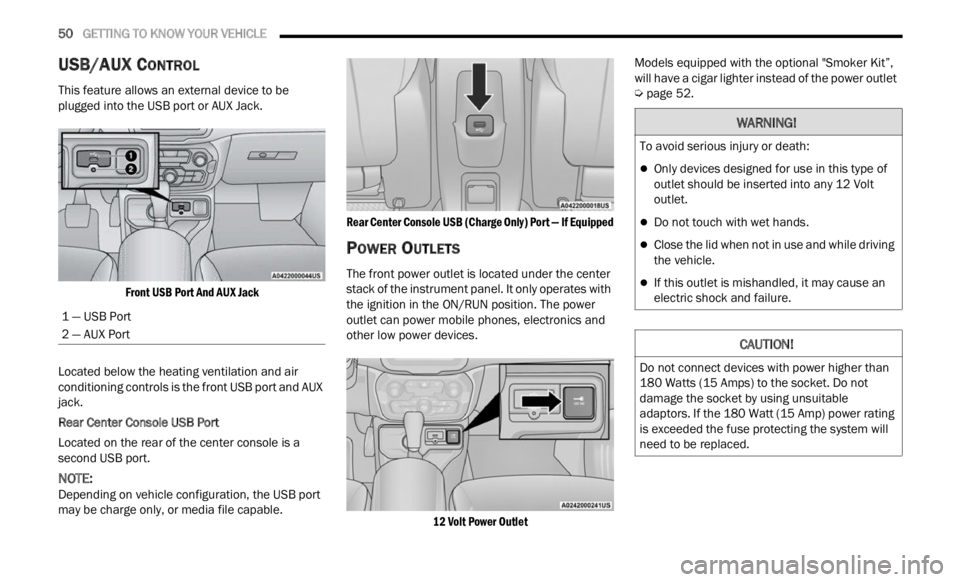
plugged into the USB port or AUX Jack.
Front USB Port And AUX Jack
Located below the heating ventilation and air
condit i
oning controls is the front USB port and AUX
jack.
Rear Center Console USB Port
Located on the rear of the center console is a
s econd
USB port.
NOTE:
Depending on vehicle configuration, the USB port
may b e
charge only, or media file capable.
Rear Center Console USB (Charge Only) Port — If Equipped
POWER OUTLETS
The front power outlet is located under the center
stack of the instrument panel. It only operates with
the ignition in the ON/RUN position. The power
outlet can power mobile phones, electronics and
other low power devices.
12 Volt Power Outlet
Models equipped with the optional "Smoker Kit”,
will h
ave a cigar lighter instead of the power outlet
Ú page 52.
1 — USB Port
2 — AUX Port
WARNING!
To avoid serious injury or death:
Only devices designed for use in this type of
outlet should be inserted into any 12 Volt
outlet.
Do not touch with wet hands.
Close the lid when not in use and while driving
the vehicle.
If this outlet is mishandled, it may cause an
electric shock and failure.
CAUTION!
Do not connect devices with power higher than
180 Watts (15 Amps) to the socket. Do not
damage the socket by using unsuitable
adaptors. If the 180 Watt (15 Amp) power rating
is exceeded the fuse protecting the system will
need to be replaced.
Page 53 of 364
GETTING TO KNOW YOUR VEHICLE 51
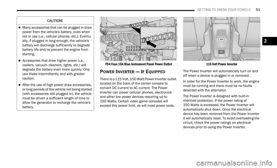
F94 Fuse 15A Blue Instrument Panel Power Outlet
POWER INVERTER — IF EQUIPPED
There is a 115 Volt, 150 Watt Power Inverter outlet
located on the back of the center console to
convert DC current to AC current. The Power
Inverter can power cellular phones, electronics
and other low power devices requiring up to
150 Watts. Certain video game consoles will
excee d
this power limit, as will most power tools.
115 Volt Power Inverter
The Power Inverter will automatically turn on and
off wh e
n a device is plugged in or removed.
In order for the Power Inverter to work, the engine
must b
e running and there must be no faults
detected with the alternator.
The Power Inverter is designed with built-in
overloa d
protection. If the power rating of
150 Watts is exceeded, the Power Inverter will
a utomat
ically shut down. Once the electrical
device has been removed from the Power Inverter
it will automatically reset. To avoid overloading the
circuit, check the power ratings on electrical
devices prior to using the Power Inverter.
CAUTION!
Many accessories that can be plugged in draw
power from the vehicle's battery, even when
not in use (i.e., cellular phones, etc.). Eventu -
ally, if plugged in long enough, the vehicle's
batte r
y will discharge sufficiently to degrade
battery life and/or prevent the engine from
starting.
Accessories that draw higher power (i.e.,
coolers, vacuum cleaners, lights, etc.) will
degrade the battery even more quickly. Only
use these intermittently and with greater
caution.
After the use of high power draw accessories,
or long periods of the vehicle not being started
(with accessories still plugged in), the vehicle
must be driven a sufficient length of time to
allow the generator to recharge the vehicle's
battery.
2
Page 54 of 364
52 GETTING TO KNOW YOUR VEHICLE
CIGAR LIGHTER — IF EQUIPPED
NOTE:
Cigar lighters can be purchased at an authorized
deale r
through Mopar® parts.
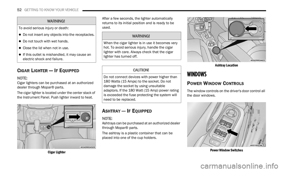
The cigar lighter is located under the center stack of
the In
strument Panel. Push lighter inward to heat.
Cigar Lighter
After a few seconds, the lighter automatically
retur
n
s to its initial position and is ready to be
used.
ASHTRAY — IF EQUIPPED
NOTE:
Ashtrays can be purchased at an authorized dealer
throug h
Mopar® parts.
The ashtray is a plastic container that can be
placed
into one of the cup holders.
Ashtray Location
WINDOWS
POWER WINDOW CONTROLS
The window controls on the driver's door control all
the door windows.
Power Window Switches
WARNING!
To avoid serious injury or death:
Do not insert any objects into the receptacles.
Do not touch with wet hands.
Close the lid when not in use.
If this outlet is mishandled, it may cause an
electric shock and failure.
WARNING!
When the cigar lighter is in use it becomes very
hot. To avoid serious injury, handle the cigar
lighter with care. Always check that the cigar
lighter has turned off.
CAUTION!
Do not connect devices with power higher than
180 Watts (15 Amps) to the socket. Do not
damage the socket by using unsuitable
adaptors. If the 180 Watt (15 Amp) power rating
is exceeded the fuse protecting the system will
need to be replaced.
Page 295 of 364
SERVICING AND MAINTENANCE 293
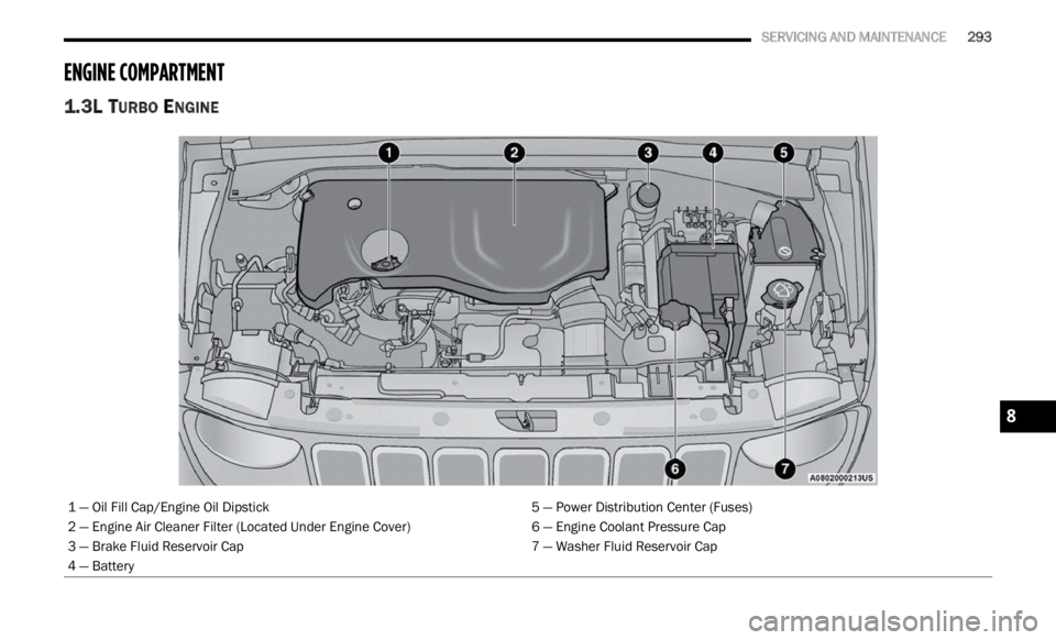
ENGINE COMPARTMENT
1.3L TURBO ENGINE
1 — Oil Fill Cap/Engine Oil Dipstick 5 — Power Distribution Center (Fuses)
2 — Engine Air Cleaner Filter (Located Under Engine Cover) 6 — Engine Coolant Pressure Cap
3 — Brake Fluid Reservoir Cap 7 — Washer Fluid Reservoir Cap
4 — Battery
8
Page 305 of 364
SERVICING AND MAINTENANCE 303
(Continued)
AUTOMATIC TRANSMISSION
Special Additives
The manufacturer strongly recommends against
using any special additives in the transmission.
Automatic Transmission Fluid (ATF) is an
engine
ered product and its performance may be
impaired by supplemental additives. Therefore, do
not add any fluid additives to the transmission. The
only exception to this policy is the use of special
dyes for diagnosing fluid leaks. Avoid using
transmission sealers as they may adversely affect
seals.
Fluid Level Check
The fluid level is preset at the factory and does not
require adjustment under normal operating
conditions. Routine fluid level checks are not
required; therefore the transmission has no
dipstick. An authorized dealer can check your
transmission fluid level using special service tools.
If you notice fluid leakage or transmission
malfunction, visit an authorized dealer immediately to have the transmission fluid level
checked. Operating the vehicle with an improper
fluid level can cause severe transmission damage.
Fluid And Filter Changes
Under normal operating conditions, the fluid
installed at the factory will provide satisfactory
lubrication for the life of the vehicle.
Routine fluid and filter changes are not required.
However
,
change the fluid and filter if the fluid
becomes contaminated (with water, etc.), or if the
transmission is disassembled for any reason.
Selection Of Lubricant
It is important to use the proper transmission fluid
to ensure optimum transmission performance and
life. Use the manufacturer specified transmission
fluid Ú page 345. It is important to maintain the
transmission fluid at the correct level using the
r ecomme
nded fluid.
NOTE:
No chemical flushes should be used in any trans -
mission; only the approved lubricant should be
u sed.
FUSES
General InformationCAUTION!
Do not use chemical flushes in your
transmission as the chemicals can damage your
transmission components. Such damage is not
covered by the New Vehicle Limited Warranty.
CAUTION!
If a transmission fluid leak occurs, visit an
authorized dealer immediately. Severe
transmission damage may occur. An authorized
dealer has the proper tools to adjust the fluid
level accurately.CAUTION!
Using a transmission fluid other than the
manufacturer recommended fluid may cause
deterioration in transmission shift quality and/or
torque converter shudder Ú page 345.
WARNING!
When replacing a blown fuse, always use an
appropriate replacement fuse with the same
amp rating as the original fuse. Never replace
a fuse with another fuse of higher amp rating.
Never replace a blown fuse with metal wires or
any other material. Failure to use proper fuses
may result in serious personal injury, fire and/
or property damage.
Before replacing a fuse, make sure that the
ignition is off and that all the other services
are switched off and/or disengaged.
8
Page 306 of 364
304 SERVICING AND MAINTENANCE
The fuses protect electrical systems against
excessive current.
When a device does not work, you must check the
electr
ical circuit inside the fuse for a break/melt.
Also please be aware that using power outlets for
extend
ed periods of time with the engine off may
result in vehicle battery discharge.
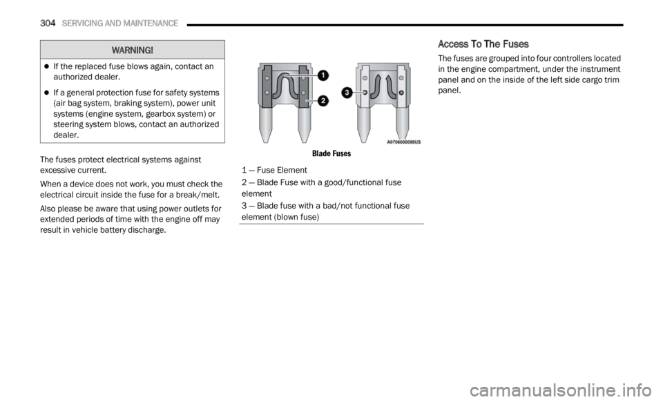
Blade Fuses
Access To The Fuses
The fuses are grouped into four controllers located
in the engine compartment, under the instrument
panel and on the inside of the left side cargo trim
panel.If the replaced fuse blows again, contact an
authorized dealer.
If a general protection fuse for safety systems
(air bag system, braking system), power unit
systems (engine system, gearbox system) or
steering system blows, contact an authorized
dealer.
WARNING!
1 — Fuse Element
2 — Blade Fuse with a good/functional fuse
element
3 — Blade fuse with a bad/not functional fuse
element (blown fuse)
Page 307 of 364
SERVICING AND MAINTENANCE 305
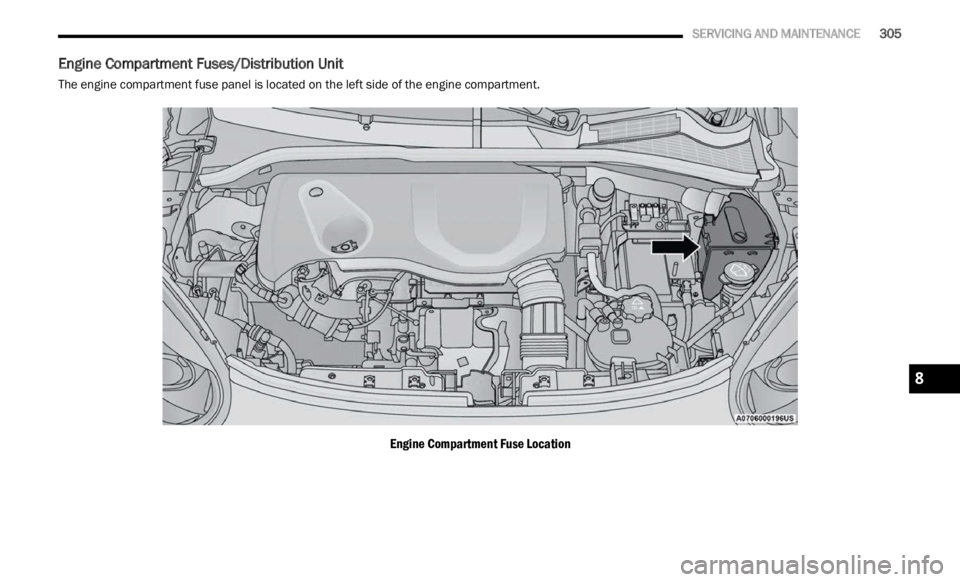
Engine Compartment Fuses/Distribution Unit
The engine compartment fuse panel is located on the left side of the engine compartment.
Engine Compartment Fuse Location
8
Page 308 of 364
306 SERVICING AND MAINTENANCE
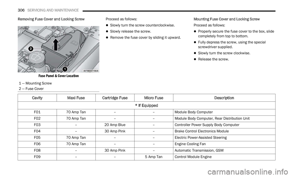
Removing Fuse Cover and Locking Screw
Fuse Panel & Cover Location
Proceed as follows:
Slowly turn the screw counterclockwise.
Slowly release the screw.
Remove the fuse cover by sliding it upward.
Mounting Fuse Cover and Locking Screw
Proceed as follows:
Properly secure the fuse cover to the box, slide
completely from top to bottom.
Fully depress the screw, using the special
screwdriver supplied.
Slowly turn the screw clockwise.
Release the screw.
1 — Mounting Screw
2 — Fuse Cover
CavityMaxi Fuse Cartridge Fuse Micro Fuse Description
* If Equipped
F01 70 Amp Tan ––Module Body Computer
F02 70 Amp Tan ––Module Body Computer, Rear Distribution Unit
F03 –20 Amp Blue –Controller Power Supply Body Computer
F04 –30 Amp Pink –Brake Control Electronics Module
F05 70 Amp Tan ––Electric Power-Assisted Steering
F06 70 Amp Tan ––Engine Cooling Fan
F08 –30 Amp Pink –Automatic Transmission, GSM
F09 ––5 Amp TanControl Module Engine
Page 309 of 364

SERVICING AND MAINTENANCE 307
F10 ––15 Amp Blue Horn
F11 ––5 Amp TanSupply Secondary Loads
F14 ––15 Amp Blue WCAC Pump/Active Grille Shutters
F15 40 Amp Orange ––Brake Control Module Pump
F16 ––5 Amp TanEngine Control Module Power, Automatic Transmission
F17 ––30 Amp Green Supply Primary Loads
F18 ––5 Amp TanIntelligent Battery Sensor
F19 ––7.5 Amp Brown Air Conditioner 1.3L Compressor
F20 ––5 Amp TanElectronic Power Four-Wheel Drive
F21 ––15 Amp Blue Fuel Pump
F22 ––10 Amp Red Power Control Module Engine
F23 ––30 Amp Green Heated Windshield *
F24 ––15 Amp Blue Electronic Unit Supply Automatic Transmission
F82 –20 Amp Yellow –Power Control Module Engine
F83 –40 Amp Green –Air Conditioning Fan
F84 ––30 Amp Green Power Supply All Wheel Drive
F87 ––5 Amp TanGear Selector Automatic Transmission
F88 ––7.5 Amp Brown Heated Outside Mirrors
F89 –30 Amp Green –Heated Rear Window
Cavity Maxi Fuse Cartridge Fuse Micro Fuse Description
* If Equipped
8