torque JEEP RENEGADE 2023 Owners Manual
[x] Cancel search | Manufacturer: JEEP, Model Year: 2023, Model line: RENEGADE, Model: JEEP RENEGADE 2023Pages: 364, PDF Size: 18.65 MB
Page 8 of 364
6
REFUELING IN EMERGENCY – IF EQUIPPED .. 280
IF YOUR ENGINE OVERHEATS ...... ...................... 281
GEAR SELECTOR OVERRIDE ...... ....................... 281
FREEING A STUCK VEHICLE ...... ........................ 282
TOWING A DISABLED VEHICLE ...... ...................283
Front–Wheel Drive (FWD) ...... ....................... 284
Four–Wheel Drive (4WD) ..... . ........................ 284
Emergency Tow Hooks — If Equipped . ..
..
. .... 284
ENHANCED ACCIDENT RESPONSE SYSTEM
(EARS) .................................................................. 285
EVEN T
DATA RECORDER (EDR) ...... ...................285
SERVICING AND MAINTENANCE
SCHEDULED SERVICING .................................... 286
Maintenance Plan ...... ................................... 287
ENGINE COMPARTMENT ..... . .............................. 293
1.3L Turbo Engine ...... ................................... 293
Checking Oil Level ..... . ................................... 294
Adding Washer Fluid . ..
..
. ............................... 294
Maintenance-Free Battery ..... . ..................... 294
Pressure Washing . ..
..
. ................................... 295
VEHICLE MAINTENANCE ..... . .............................. 295
Engine Oil ...................................................... 295
Engin e Oil Filter . ..
..
. ....................................... 296
Engine Air Cleaner Filter ..... . ........................ 296
Air Conditioner Maintenance . ..
..
. .................. 296Body Lubrication .....
.
..................................... 297
Windshield Wiper Blades ..... . ....................... 297
Exhaust System ..... . ...................................... 298
Cooling System . ..
..
. ........................................ 299
Brake System ..... . .......................................... 302
Automatic Transmission . ..
..
. ........................ 303
Fuses.............................................................. 303
Bulb
Replacement. ..
..
. ................................... 311
TIRES..................................................................... 322
Tire
Safety Information ...... ........................... 322
Tires — General Information . ..
..
. .................. 329
Tire Types....................................................... 332
Spar e
Tires — If Equipped . ..
. .
. ....................... 333
Wheel And Wheel Trim Care ..... . ................... 334
Snow Traction Devices . ..
..
. ........................... 335
Tire Rotation Recommendations ..... . .......... 336
DEPARTMENT OF TRANSPORTATION
UNIFORM TIRE QUALITY GRADES ..... .
............. 337
Treadwear ...................................................... 337
Tract ion Grades . ..
..
. ....................................... 337
Temperature Grades ..... . ............................... 337
STORING THE VEHICLE . ..
..
. ................................. 338
BODYWORK ...... ................................................... 338
Protection From Atmospheric Agents ...... .... 338
Body And Underbody Maintenance. ..
..
. ........ 338
Preserving The Bodywork ..... . ....................... 338INTERIORS .....
.
..................................................... 339
Seats And Fabric Parts ...... ........................... 339
Plastic And Coated Parts ..... . ........................ 339
Leather Surfaces. ..
..
. ..................................... 340
Glass Surfaces ..... . ....................................... 340
TECHNICAL SPECIFICATIONS
VEHICLE IDENTIFICATION NUMBER (VIN) ........ 341
BRAKE SYSTEM ...... ............................................. 341
WHEEL AND TIRE TORQUE SPECIFICATIONS .. 341 Tor que Specifications ...... ............................. 341
FUEL REQUIREMENTS . ..
..
. ................................... 342
1.3L Turbo Engine ...... ................................... 342
Reformulated Gasoline..... . ........................... 342
Gasoline/Oxygenate Blends . ..
..
. .................. 342
E-85 Usage In Non-Flex Fuel Vehicles ..... . ... 343
CNG And LP Fuel System Modifications . ..
..
. 343
Methylcyclopentadienyl Manganese
Tricarbonyl (MMT) In Gasoline . .....
............... 343
Materials Added To Fuel ..... . ......................... 343
Fuel System Cautions ..... . ............................. 344
FLUID CAPACITIES . ..
..
. ......................................... 344
ENGINE FLUIDS AND LUBRICANTS ...... ............ 345
CHASSIS FLUIDS AND LUBRICANTS ...... .......... 345
Page 75 of 364
GETTING TO KNOW YOUR INSTRUMENT PANEL 73
Low Fuel Warning Light
When the fuel level reaches
approximately 1.3–1.8 gal (5–7 L) this
light
will turn on, and remain on until fuel
is added.
LaneSense Warning Light — If Equipped
The LaneSense system provides the
driver with visual and steering torque
warni n
gs when the vehicle starts to drift
out of its lane unintentionally without the
use of a turn signal Ú page 117.
When the LaneSense system senses a lane drift
situation, the LaneSense indicator changes
from solid green to solid yellow.
When the LaneSense system senses the lane
has been approached and is in a lane departure
situation, the LaneSense indicator changes
from solid white/green to flashing yellow.
Service LaneSense Warning Light —
If Equipped
This warning light will illuminate when the
LaneSense system is not operating and
r e q
ui
r
es service. Please see an
authorized dealer.
Engine Check/Malfunction Indicator
Warning Light (MIL)
The Engine Check/Malfunction Indicator
Light (MIL) is a part of an Onboard
D ia
gn
os
tic System called OBD II that
monitors engine and automatic
transmission control systems. This warning light
will illuminate when the ignition is in the ON/RUN
position before engine start. If the bulb does not
come on when turning the ignition switch from OFF
to ON/RUN, have the condition checked promptly.
The vehicle should be serviced if the light stays on
throug h
several typical driving styles. In most
situations, the vehicle will drive normally and will
not require towing.
When the engine is running, the MIL may flash to
alert
serious conditions that could lead to
immediate loss of power or severe catalytic
converter damage. The vehicle should be serviced
as soon as possible if this occurs.
Service 4WD Warning Light — If Equipped
This warning light will illuminate to signal
a fault with the 4WD system. If the light
stays
on or comes on during driving, it
means that the 4WD system is not
functioning properly and that service is required.
We recommend you drive to the nearest service
center and have the vehicle serviced immediately.
WARNING!
A malfunctioning catalytic converter, as
referenced above, can reach higher
temperatures than in normal operating
conditions. This can cause a fire if you drive
slowly or park over flammable substances such
as dry plants, wood, cardboard, etc. This could
result in death or serious injury to the driver,
occupants or others.
CAUTION!
Prolonged driving with the Malfunction Indicator
Light (MIL) on could cause damage to the
vehicle control system. It also could affect fuel
economy and driveability. If the MIL is flashing,
severe catalytic converter damage and power
loss will soon occur. Immediate service is
required.
3
Page 77 of 364
GETTING TO KNOW YOUR INSTRUMENT PANEL 75
Towing Hook Breakdown Warning Light —
If Equipped
This light illuminates when there is a
failure with the tow hook. Contact an
a ut
h or
i
zed dealer for service.
Transmission Temperature Warning Light
This light indicates that the transmission
fluid temperature is running hot. This
may occ
ur with severe usage, such as
trailer towing. If this light turns on, safely
pull over and stop the vehicle. Then, shift the
transmission into PARK and run the engine at idle
or slightly higher until the light turns off.
4WD Over Temperature Warning Light
The icon will appear on the instrument
panel display to indicate overheating of
t h e
4
W
D system. The mode selected by
the user will be applied as soon as the
system exits the overheating condition.
YELLOW INDICATOR LIGHTS
4WD Low Indicator Light — If Equipped
This light alerts the driver that the vehicle
is in the 4WD Low mode. The front and
rear d
riveshafts are mechanically locked
together forcing the front and rear
wheels to rotate at the same speed. Low range provides a greater gear reduction ratio to provide
increased torque at the wheels
Ú page 90.
4WD Lock Indicator Light
This light alerts the driver that the vehicle
is in the four-wheel drive LOCK mode.
The f r
ont and rear driveshafts are
mechanically locked together, forcing the
front and rear wheels to rotate at the same speed
Ú page 90.
Dusk Sensor Malfunction Indicator Light
This symbol lights up (together with a
dedicated message on display) when a
dusk s
ensor malfunction is detected
Ú page 38.
Electronic Stability Control (ESC) Active
Warning Light — If Equipped
This warning light will indicate when the
ESC system is Active. The ESC Indicator
Light
in the instrument cluster will come
on when the ignition is placed in the ON/
RUN or ACC/ON/RUN position, and when ESC is
activated. It should go out with the engine running.
If the ESC Indicator Light comes on continuously
with the engine running, a malfunction has been
detected in the ESC system. If this warning light
remains on after several ignition cycles, and the
vehicle has been driven several miles (kilometers)
CAUTION!
The TPMS has been optimized for the original
equipment tires and wheels. TPMS pressures
and warning have been established for the tire
size equipped on your vehicle. Undesirable sys -
tem operation or sensor damage may result
w hen u
sing replacement equipment that is not
of the same size, type, and/or style. Aftermarket
wheels can cause sensor damage. Using after -
market tire sealants may cause the Tire Pres -
sure Monitoring System (TPMS) sensor to
b ecome
inoperable. After using an aftermarket
tire sealant it is recommended that you take
your vehicle to an authorized dealer to have your
sensor function checked.
WARNING!
If you continue operating the vehicle when the
Transmission Temperature Warning Light is
illuminated you could cause the fluid to boil over,
come in contact with hot engine or exhaust
components and cause a fire.
CAUTION!
Continuous driving with the Transmission
Temperature Warning Light illuminated will
eventually cause severe transmission damage
or transmission failure.
3
Page 91 of 364

STARTING AND OPERATING 89
these conditions, using a lower gear will improve
performance and extend transmission life by
reducing excessive shifting and heat buildup.
If the transmission temperature exceeds normal
operat i
ng limits, the transmission controller may
modify the transmission shift schedule, reduce
engine torque, and/or expand the range of torque
converter clutch engagement. This is done to
prevent transmission damage due to overheating.
If the transmission becomes extremely hot, the
Trans m
ission Temperature Warning Light may
illuminate and the transmission may operate
differently until the transmission cools down.
During cold temperatures, transmission operation
may be
modified depending on engine and
transmission temperature as well as vehicle
speed. This feature improves warm up time of the
engine and transmission to achieve maximum
efficiency. Engagement of the torque converter
clutch, and shifts into EIGHTH or NINTH gear, are
inhibited until the transmission fluid is warm.
Normal operation will resume once the
transmission temperature has risen to a suitable
level.
AutoStick
AutoStick is a driver-interactive transmission
f eatu r
e providing manual shift control, giving you
more control of the vehicle. AutoStick allows you to
maximize engine braking, eliminate undesirable
upshifts and downshifts, and improve overall vehicle performance. This system can also provide
you with more control during passing, city driving,
cold slippery conditions, mountain driving, trailer
towing and many other situations.
Operation
When the gear selector is in the AutoStick position
(besi
d
e the DRIVE position), it can be moved
forward and rearward. This allows the driver to
manually select the transmission gear being used.
Moving the gear selector forward (-) triggers a
downshift, and rearward (+) an upshift. The current
gear is displayed in the instrument cluster.
NOTE:
In AutoStick mode, the transmission will only shift
up or d
own when the driver moves the gear
selector rearward (+) or forward (-), except as
described below:
The transmission will automatically upshift
when necessary to prevent engine overspeed.
The transmission will automatically downshift
as the vehicle slows (to prevent engine lugging)
and will display the current gear.
The transmission will automatically downshift to
FIRST or SECOND gear (depending on model)
when coming to a stop. After a stop, the driver
should manually upshift (+) the transmission as
the vehicle is accelerated.
You can start out (from a stop) in FIRST or
SECOND gear. Starting out in SECOND gear can
be helpful in snow or icy conditions. Tap the gear
selector forward or rearward to select the
desired gear after the vehicle is brought to a
stop.
If a requested downshift would cause the
engine to overspeed, that shift will not occur.
The system will ignore attempts to upshift at too
low of a vehicle speed.
Avoid using Cruise Control when AutoStick is
engaged because the transmission will not shift
automatically.
Transmission shifting will be more noticeable
when AutoStick is enabled.
The system may revert to automatic shift mode
if a fault or overheat condition is detected.
To disengage AutoStick mode, return the gear
select
or to the DRIVE position. You can shift in or
out of the AutoStick position at any time without
taking your foot off the accelerator pedal.
WARNING!
Do not downshift for additional engine braking
on a slippery surface. The drive wheels could
lose their grip and the vehicle could skid,
causing a collision or personal injury.
4
Page 92 of 364

90 STARTING AND OPERATING
TRANSMISSION LIMP HOME MODE
Transmission function is electronically monitored
for abnormal conditions. If a condition is detected
that could result in transmission damage,
Transmission Limp Home Mode is activated. In this
mode, the transmission may operate only in a fixed
gear, or may remain in neutral. The Malfunction
Indicator Light (MIL) may be illuminated. Limp
Home Mode may allow the vehicle to be driven to
an authorized dealer for service without damaging
the transmission.
In the event of a momentary problem, the
trans m
ission can be reset to regain all forward
gears by performing the following steps:
1. Stop the vehicle.
2. S hif
t the transmission into PARK, if possible. If
n ot
,
s
hift the transmission to NEUTRAL.
3. Push and hold the ignition switch until the engin
e turns off.
4. Wait approximately 30 seconds.
5. Res
tart the engine.
6. S hif
t into the desired gear range. If the
p r
ob l
e
m is no longer detected, the
transmission will return to normal operation.
NOTE:
Even if the transmission can be reset, we
recomm e
nd that you visit an authorized dealer at your earliest possible convenience. An authorized
dealer has diagnostic equipment to determine if
the problem could recur. If the transmission
cannot be reset, authorized dealer service is
required.
IGNITION PARK INTERLOCK
(K
EYLESS VEHICLE)
This vehicle is equipped with an Ignition Park
Interlock, which requires the transmission to be in
PARK before the ignition can be turned to the OFF
position. Also, the transmission is locked in PARK
whenever the ignition is in the OFF position.
BRAKE TRANSMISSION SHIFT
I
NTERLOCK (BTSI) SYSTEM
This vehicle is equipped with a BTSI that holds the
transmission gear selector in PARK unless the
brakes are applied. To shift the transmission out of
PARK, the ignition must be in the RUN position
(engine running or not) and the brake pedal must
be pressed.
The brake pedal must also be pressed before
pushi n
g the button on the gear selector to shift
from NEUTRAL into DRIVE or REVERSE when the
vehicle is stopped or moving at low speeds.
FOUR-WHEEL DRIVE
Active Drive (4WD) And Active Drive Low (4WD
LOW)
Your vehicle may be equipped with a Power
Transf
er Unit (PTU). This system is automatic with
no driver inputs or additional driving skills
required. Under normal driving conditions, the
front wheels provide most of the traction. If the
front wheels begin to lose traction, power is shifted
automatically to the rear wheels. The greater the
front wheel traction loss, the greater the power
transfer to the rear wheels.
Additionally, on dry pavement under heavy throttle
input
(where one may have no wheel spin), torque
will be sent to the rear in a preemptive effort to
improve vehicle launch and performance
characteristics.
CAUTION!
All wheels must have the same size and type
tires. Unequal tire sizes must not be used.
Unequal tire size may cause failure of the power
transfer unit.
Page 93 of 364
STARTING AND OPERATING 91
FOUR-WHEEL DRIVE (4WD)
The four-wheel drive (4WD) is fully automatic in
normal driving mode.
NOTE:
It is not possible to carry out the change of mode
when t
he vehicle exceeds the speed of 75 mph
( 1
2 0
k m
/h).
Enabling Four-Wheel Drive (4WD)
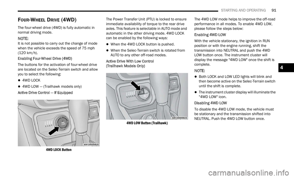
The buttons for the activation of four-wheel drive
a re l oc
ated on the Selec-Terrain switch and allow
you to select the following:
4WD LOCK
4WD LOW — (Trailhawk models only)
Active Drive Control — If Equipped
4WD LOCK Button
The Power Transfer Unit (PTU) is locked to ensure
immed
i
ate availability of torque to the rear drive
axles. This feature is selectable in AUTO mode and
automatic in the other driving mode. 4WD LOCK
can be enabled by the following ways:
When the 4WD LOCK button is pushed.
When the Selec-Terrain switch is rotated from
AUTO to any other off-road modes.
Active Drive With Low Control
(Trailhawk Models Only)
4WD LOW Button (Trailhawk)
The 4WD LOW mode helps to improve the off-road
perform
ance in all modes. To enable 4WD LOW,
please follow the steps below:
Enabling 4WD LOW
With the vehicle stationary, the ignition in RUN
p osition
or with the engine running, shift the
transmission into NEUTRAL and push the 4WD
LOW button once. The instrument cluster will
display the message "4WD LOW" once the shift is
complete.
NOTE:
Both LOCK and LOW LED lights will blink and
then become active on the Selec-Terrain switch
until the shift is complete.
The instrument cluster display will illuminate the
"4WD LOW" icon.
Disabling 4WD LOW
To disable the 4WD LOW mode, the vehicle must
be st a
tionary and the transmission shifted into
NEUTRAL. Push the 4WD LOW button once.
4
Page 119 of 364
STARTING AND OPERATING 117
LANESENSE — IF EQUIPPED
LANESENSE OPERATION
The LaneSense system is operational at speeds
above 37 mph (60 km/h) and below 112 mph
(180 km
/h). The LaneSense system uses a
f or
wa
rd
looking camera to detect lane markings
and measure vehicle position within the lane
boundaries.
When both lane markings are detected and the
driver
unintentionally drifts out of the lane (no turn
signal applied), the LaneSense system provides a
haptic warning in the form of torque applied to the
steering wheel to prompt the driver to remain within
the lane boundaries. If the driver continues to
unintentionally drift out of the lane, the LaneSense
system provides a visual warning through the
instrument cluster display to prompt the driver to
remain within the lane boundaries.
The driver may manually override the haptic warning
by app l
ying torque to the steering wheel at any time.
When only a single lane marking is detected and
the dr
iver unintentionally drifts across the lane
marking (no turn signal applied), the LaneSense
system provides a visual warning through the
instrument cluster display to prompt the driver to
remain within the lane. When only a single lane
marking is detected, a haptic (torque) warning will
not be provided.
NOTE:
When operating conditions have been met, the
LaneSe n
se system will monitor if the driver’s
hands are on the steering wheel and provides an
audible warning to the driver when the driver’s
hands are not detected on the steering wheel. The
system will cancel if the driver does not return their
hands to the wheel.
TURNING LANESENSE ON OR OFF
The LaneSense button is located on the
center stack.
To turn the LaneSense system on, push the
La neSen
se button (LED turns off). A “Lane Sense
On” message is shown in the instrument cluster
display.
To turn the LaneSense system off, push the
LaneSen
se button once (LED turns on).
NOTE:
The LaneSense system will retain the last system
state
on or off from the last ignition cycle when the
ignition is changed to the ON/RUN position.
LANESENSE WARNING MESSAGE
The LaneSense system will indicate the current
lane drift condition through the instrument cluster
display.
Base Instrument Cluster Display — If Equipped
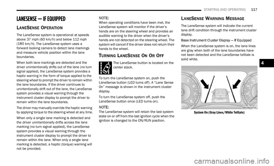
When the LaneSense system is on, the lane lines
a re gr
ay when both of the lane boundaries have
not been detected and the LaneSense telltale is
solid white.
System On (Gray Lines/White Telltale)
4
Page 120 of 364
118 STARTING AND OPERATING
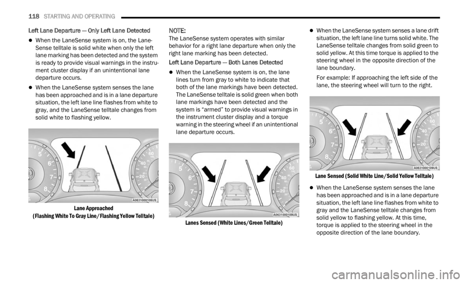
Left Lane Departure — Only Left Lane Detected
When the LaneSense system is on, the Lane-
Sense telltale is solid white when only the left
lane m
arking has been detected and the system
is ready to provide visual warnings in the instru -
ment cluster display if an unintentional lane
depar t
ure occurs.
When the LaneSense system senses the lane
has been approached and is in a lane departure
situation, the left lane line flashes from white to
gray, and the LaneSense telltale changes from
solid white to flashing yellow.
Lane Approached
(Flash
ing White To Gray Line/Flashing Yellow Telltale)
NOTE:
The LaneSense system operates with similar
behav i
or for a right lane departure when only the
right lane marking has been detected.
Left Lane Departure — Both Lanes Detected
When the LaneSense system is on, the lane
lines turn from gray to white to indicate that
both of the lane markings have been detected.
The LaneSense telltale is solid green when both
lane markings have been detected and the
system is “armed” to provide visual warnings in
the instrument cluster display and a torque
warning in the steering wheel if an unintentional
lane departure occurs.
Lanes Sensed (White Lines/Green Telltale)
When the LaneSense system senses a lane drift
situation, the left lane line turns solid white. The
LaneSense telltale changes from solid green to
solid yellow. At this time torque is applied to the
steering wheel in the opposite direction of the
lane boundary.
For example: If approaching the left side of the
lane,
the steering wheel will turn to the right.
Lane Sensed (Solid White Line/Solid Yellow Telltale)
When the LaneSense system senses the lane
has been approached and is in a lane departure
situation, the left lane line flashes from white to
gray and the LaneSense telltale changes from
solid yellow to flashing yellow. At this time,
torque is applied to the steering wheel in the
opposite direction of the lane boundary.
Page 121 of 364
STARTING AND OPERATING 119
For example: If approaching the left side of the
lane, the steering wheel will turn to the right.
Lane Approached
(Flas h
ing White To Gray Line/Flashing Yellow Telltale)
NOTE:
The LaneSense system operates with similar
behav i
or for a right lane departure.
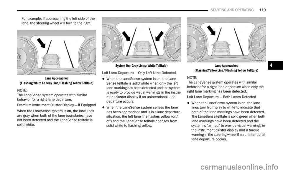
Premium Instrument Cluster Display — If Equipped
When the LaneSense system is on, the lane lines
are g r
ay when both of the lane boundaries have
not been detected and the LaneSense telltale is
solid white.
System On (Gray Lines/White Telltale)
Left Lane Departure — Only Left Lane Detected
When the LaneSense system is on, the Lane-
Sense telltale is solid white when only the left
lane m
arking has been detected and the system
is ready to provide visual warnings in the instru -
ment cluster display if an unintentional lane
depar t
ure occurs.
When the LaneSense system senses the lane
has been approached and is in a lane departure
situation, the left lane line flashes yellow (on/
off) and the LaneSense telltale changes from
solid white to flashing yellow.
Lane Approached
(Flas h
ing Yellow Line/Flashing Yellow Telltale)
NOTE:
The LaneSense system operates with similar
behav i
or for a right lane departure when only the
right lane marking has been detected.
Left Lane Departure — Both Lanes Detected
When the LaneSense system is on, the lane
lines turn from gray to white to indicate that
both of the lane markings have been detected.
The LaneSense telltale is solid green when both
lane markings have been detected and the
system is “armed” to provide visual warnings in
the instrument cluster display and a torque
warning in the steering wheel if an unintentional
lane departure occurs.
4
Page 122 of 364
120 STARTING AND OPERATING
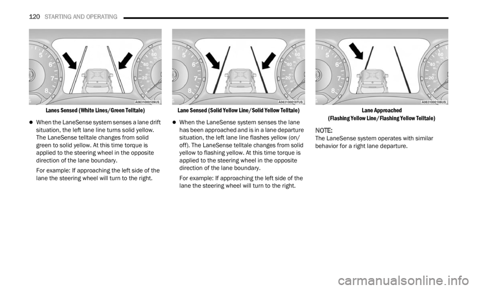
Lanes Sensed (White Lines/Green Telltale)
When the LaneSense system senses a lane drift
situation, the left lane line turns solid yellow.
The LaneSense telltale changes from solid
green to solid yellow. At this time torque is
applied to the steering wheel in the opposite
direction of the lane boundary.
For example: If approaching the left side of the
lane t
he steering wheel will turn to the right.
Lane Sensed (Solid Yellow Line/Solid Yellow Telltale)
When the LaneSense system senses the lane
has been approached and is in a lane departure
situation, the left lane line flashes yellow (on/
off). The LaneSense telltale changes from solid
yellow to flashing yellow. At this time torque is
applied to the steering wheel in the opposite
direction of the lane boundary.
For example: If approaching the left side of the
lane
t
he steering wheel will turn to the right.
Lane Approached
(Flas h
ing Yellow Line/Flashing Yellow Telltale)
NOTE:
The LaneSense system operates with similar
behav i
or for a right lane departure.