clock JEEP WAGONEER 2023 Owners Manual
[x] Cancel search | Manufacturer: JEEP, Model Year: 2023, Model line: WAGONEER, Model: JEEP WAGONEER 2023Pages: 396, PDF Size: 15.17 MB
Page 59 of 396
GETTING TO KNOW YOUR VEHICLE57
EXTERIOR LIGHTS
HEADLIGHT SWITCH
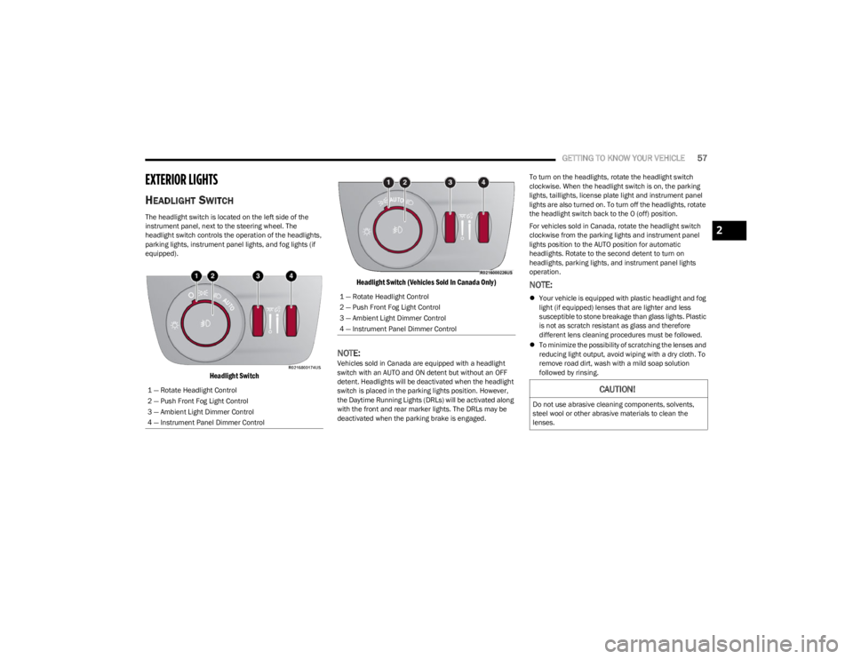
The headlight switch is located on the left side of the
instrument panel, next to the steering wheel. The
headlight switch controls the operation of the headlights,
parking lights, instrument panel lights, and fog lights (if
equipped).
Headlight Switch Headlight Switch (Vehicles Sold In Canada Only)
NOTE:Vehicles sold in Canada are equipped with a headlight
switch with an AUTO and ON detent but without an OFF
detent. Headlights will be deactivated when the headlight
switch is placed in the parking lights position. However,
the Daytime Running Lights (DRLs) will be activated along
with the front and rear marker lights. The DRLs may be
deactivated when the parking brake is engaged. To turn on the headlights, rotate the headlight switch
clockwise. When the headlight switch is on, the parking
lights, taillights, license plate light and instrument panel
lights are also turned on. To turn off the headlights, rotate
the headlight switch back to the O (off) position.
For vehicles sold in Canada, rotate the headlight switch
clockwise from the parking lights and instrument panel
lights position to the AUTO position for automatic
headlights. Rotate to the second detent to turn on
headlights, parking lights, and instrument panel lights
operation.
NOTE:
Your vehicle is equipped with plastic headlight and fog
light (if equipped) lenses that are lighter and less
susceptible to stone breakage than glass lights. Plastic
is not as scratch resistant as glass and therefore
different lens cleaning procedures must be followed.
To minimize the possibility of scratching the lenses and
reducing light output, avoid wiping with a dry cloth. To
remove road dirt, wash with a mild soap solution
followed by rinsing.
1 — Rotate Headlight Control
2 — Push Front Fog Light Control
3 — Ambient Light Dimmer Control
4 — Instrument Panel Dimmer Control1 — Rotate Headlight Control
2 — Push Front Fog Light Control
3 — Ambient Light Dimmer Control
4 — Instrument Panel Dimmer Control
CAUTION!
Do not use abrasive cleaning components, solvents,
steel wool or other abrasive materials to clean the
lenses.
2
23_WS_OM_EN_USC_t.book Page 57
Page 60 of 396
58GETTING TO KNOW YOUR VEHICLE
MULTIFUNCTION LEVER
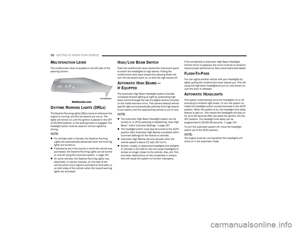
The multifunction lever is located on the left side of the
steering column.
Multifunction Lever
DAYTIME RUNNING LIGHTS (DRLS)
The Daytime Running Lights (DRLs) come on whenever the
engine is running, and the low beams are not on. The
lights will remain on until the ignition is placed in the OFF
or ON/RUN position, or the parking brake is engaged. The
headlight switch must be used for normal nighttime
driving.
NOTE:
For vehicles sold in Canada, the Daytime Running
Lights will automatically deactivate when the front fog
lights are turned on.
If allowed by law in the country in which the vehicle was
purchased, the Daytime Running Lights can be turned
on and off using the Uconnect system
Úpage 197.
On some vehicles, the Daytime Running Lights may
deactivate, or reduce intensity, on one side of the
vehicle (when a turn signal is activated on that side), or
on both sides of the vehicle (when the hazard warning
lights are activated).
HIGH/LOW BEAM SWITCH
Push the multifunction lever toward the instrument panel
to switch the headlights to high beams. Pulling the
multifunction lever back toward the steering wheel will
turn the low beams back on, or shut the high beams off.
AUTOMATIC HIGH BEAMS —
I
F EQUIPPED
The Automatic High Beam Headlight system provides
increased forward lighting at night by automating high
beam control through the use of a digital camera mounted
on the inside rearview mirror. This camera detects vehicle
specific light and automatically switches from high beams
to low beams until the approaching vehicle is out of view.
NOTE:
The Automatic High Beam Headlight system can be
turned on or off by selecting or deselecting “Auto High
Beam” within Uconnect Settings
Úpage 197.
The headlight switch must also be turned to the AUTO
position after Automatic High Beams is enabled within
Uconnect Settings for the feature to activate.
Automatic High Beams will only activate when the
vehicle speed is above 22 mph (35 km/h).
Broken, muddy, or obstructed headlights and taillights
of vehicles in the field of view will cause headlights to
remain on longer (closer to the vehicle). Also, dirt, film,
and other obstructions on the windshield or camera
lens will cause the system to function improperly. If the windshield or Automatic High Beam Headlight
Control mirror is replaced, the mirror must be re-aimed to
ensure proper performance. See a local authorized dealer.
FLASH-TO-PASS
You can signal another vehicle with your headlights by
lightly pulling the multifunction lever toward you. This will
cause the high beam headlights to turn on, and remain on,
until the lever is released.
AUTOMATIC HEADLIGHTS
This system automatically turns the headlights on or off
according to ambient light levels. To turn the system on,
rotate the headlight switch counterclockwise to the AUTO
position. When the system is on, the headlight time delay
feature is also on. This means the headlights will stay on
for up to 90 seconds after you place the ignition into the
OFF position. The headlight time delay can be
programmed 0/30/60/90 seconds
Úpage 197.
To turn the automatic system off, move the headlight
switch out of the AUTO position.
NOTE:The engine must be running before the headlights will
come on in the automatic mode.
23_WS_OM_EN_USC_t.book Page 58
Page 61 of 396

GETTING TO KNOW YOUR VEHICLE59
PARKING LIGHTS AND PANEL LIGHTS
To turn on the parking lights and instrument panel lights,
rotate the headlight switch clockwise. To turn off the
parking lights, rotate the headlight switch back to the O
(off) position.
NOTE:Vehicles sold in Canada are equipped with a headlight
switch with an AUTO and ON detent but without an OFF
detent. Headlights will be deactivated when the headlight
switch is placed in the parking lights position. However,
the Daytime Running Lights (DRLs) will be activated along
with the front and rear marker lights. The DRLs may be
deactivated when the parking brake is engaged.
HEADLIGHTS ON AUTOMATICALLY WITH
W
IPERS
If your vehicle is equipped with Automatic Headlights, it
also has this customer-programmable feature. When your
headlights are in the automatic mode and the engine is
running, they will automatically turn on when the wiper
system is on. This feature is programmable through the
Uconnect system
Úpage 197.
NOTE:When your headlights come on during the daytime, the
vehicle will monitor outside brightness and decide if the
instrument panel needs to be dimmed or not
Úpage 60.
HEADLIGHT ILLUMINATION ON
A
PPROACH
When enabled, the headlights, exterior door handle
pocket lights (if equipped), and interior lights will
illuminate when the unlock button on the key fob is
pushed as the operator is approaching the vehicle. This
feature can be turned on/off, and the length of time the
headlights stay on can be programmed for up to
90 seconds within Uconnect Settings
Úpage 197.
Proximity Wake-Up — If Equipped
This feature is enabled/disabled within the Uconnect
system, and is activated when the operator approaches
the driver’s door, passenger’s door, or liftgate with a valid
key fob on their person. Some exterior and interior lights
will illuminate in order to provide an increased sense of
welcome and security as the operator approaches the
vehicle in the dark. “Headlight Illumination On Approach”
must be selected and set to a time value other than zero
within Uconnect Settings for Proximity Wake-Up to
activate.
The doors may be locked or unlocked for this feature to
activate, as long as the ignition is in the OFF position, or
during a Remote Start event. It will not activate if the doors
are locked and the ignition was placed in the ON/RUN
position.
NOTE:Proximity Wake-Up may not activate under the following
conditions:
After numerous consecutive activations, in order to
conserve the vehicle’s battery
After the vehicle’s engine has been off for several days Headlight Animation — If Equipped
When “Headlight Illumination On Approach” is turned on,
and set to a time value above zero, the exterior lights
illuminate in a theatrical manner during approach to the
vehicle. This feature is activated in the following
situations:
Proximity Wake-Up (if equipped) is activated
Remote Start is activated
The unlock button on the key fob is pushed
NOTE:For Headlight Animation to activate with Remote Start or
with the push of the unlock button, “Greeting Lights” must
also be selected within the Uconnect system.
HEADLIGHT DELAY
To aid in your exit, your vehicle is equipped with a
headlight delay that will leave the headlights on for
approximately 90 seconds. This delay is initiated when the
ignition is placed in the OFF position while the headlight
switch is on, and then the headlight switch is cycled off.
Headlight delay can be canceled by either turning the
headlight switch on then off, or by placing the ignition in
the ON position.
NOTE:The headlight delay time is programmable through
Uconnect Settings Úpage 197.
LIGHTS-ON REMINDER
If the headlights or parking lights are left on after the
ignition is placed in the OFF position, a chime will sound
when the driver’s door is opened.
2
23_WS_OM_EN_USC_t.book Page 59
Page 186 of 396
184STARTING AND OPERATING
TRAILER HITCH RECEIVER COVER
R
EMOVAL — IF EQUIPPED
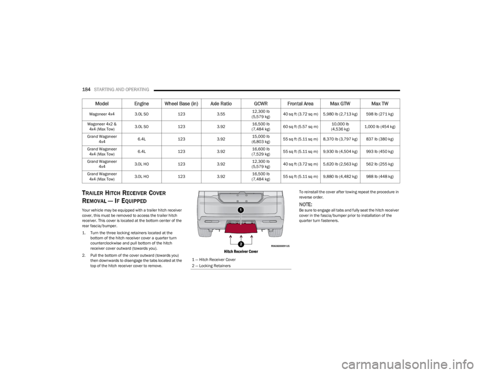
Your vehicle may be equipped with a trailer hitch receiver
cover, this must be removed to access the trailer hitch
receiver. This cover is located at the bottom center of the
rear fascia/bumper.
1. Turn the three locking retainers located at the
bottom of the hitch receiver cover a quarter turn
counterclockwise and pull bottom of the hitch
receiver cover outward (towards you).
2. Pull the bottom of the cover outward (towards you) then downwards to disengage the tabs located at the
top of the hitch receiver cover to remove.
Hitch Receiver Cover
To reinstall the cover after towing repeat the procedure in
reverse order.
NOTE:Be sure to engage all tabs and fully seat the hitch receiver
cover in the fascia/bumper prior to installation of the
quarter turn fasteners.
Wagoneer 4x4 3.0L SO
1233.5512,300 lb
(5,579 kg) 40 sq ft (3.72 sq m) 5,980 lb (2,713 kg) 598 lb (271 kg)
Wagoneer 4x2 & 4x4 (Max Tow) 3.0L SO
1233.9216,500 lb
(7,484 kg) 60 sq ft (5.57 sq m) 10,000 lb
(4,536 kg) 1,000 lb (454 kg)
Grand Wagoneer 4x4 6.4L
1233.9215,000 lb
(6,803 kg) 55 sq ft (5.11 sq m) 8,370 lb (3,797 kg) 837 lb (380 kg)
Grand Wagoneer 4x4 (Max Tow) 6.4L
1233.9216,600 lb
(7,529 kg) 55 sq ft (5.11 sq m) 9,930 lb (4,504 kg) 993 lb (450 kg)
Grand Wagoneer 4x4 3.0L HO
1233.9212,300 lb
(5,579 kg) 40 sq ft (3.72 sq m) 5,620 lb (2,563 kg) 562 lb (255 kg)
Grand Wagoneer 4x4 (Max Tow) 3.0L HO
1233.9216,500 lb
(7,484 kg) 55 sq ft (5.11 sq m) 9,880 lb (4,482 kg) 988 lb (448 kg)
Model
Engine Wheel Base (in) Axle Ratio GCWR Frontal Area Max GTW Max TW
1 — Hitch Receiver Cover
2 — Locking Retainers
23_WS_OM_EN_USC_t.book Page 184
Page 207 of 396
MULTIMEDIA205
Clock
New Speed Zone Indication This setting will allow you to set if the system will warn you that the speed limit has
changed in an area. The available options are “Off”, “Visual”, and “Visual + Chime”.
Rear ParkSense Braking Assist This setting will turn the Rear ParkSense Braking Assist on or off.
Setting NameDescription
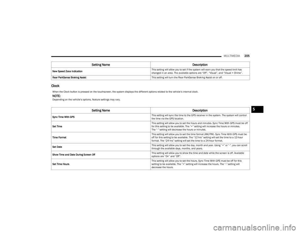
When the Clock button is pressed on the touchscreen, the system displays the different options related to the vehicle’s internal clock.
NOTE:Depending on the vehicle’s options, feature settings may vary.
Setting NameDescription
Sync Time With GPS This setting will sync the time to the GPS receiver in the system. The system will control
the time via the GPS location.
Set Time This setting will allow you to set the hours and minutes. Sync Time With GPS must be off
for this setting to be available. The “+” setting will increase the hours or minutes.
The “-” setting will decrease the hours or minutes.
Time Format This setting will allow you to set the time format (AM/PM). Sync Time With GPS must be
off for this setting to be available. The “12 hrs” setting will set the time to a 12-hour
format. The “24 hrs” setting will set the time to a 24-hour format.
Set Date This setting will allow you to set the day, month and year. Using “+” or “-”, you can scroll
through the available days, months, and years.
Show Time and Date During Screen Off This setting will allow you to show the time and date while the screen is off. Available
options are “On” and “Off”.
Set Time Hours This setting will allow you to set the hours. Sync Time With GPS must be off for this
setting to be available. The “+” setting will increase the hours. The “-” setting will
decrease the hours.
5
23_WS_OM_EN_USC_t.book Page 205
Page 223 of 396
MULTIMEDIA221
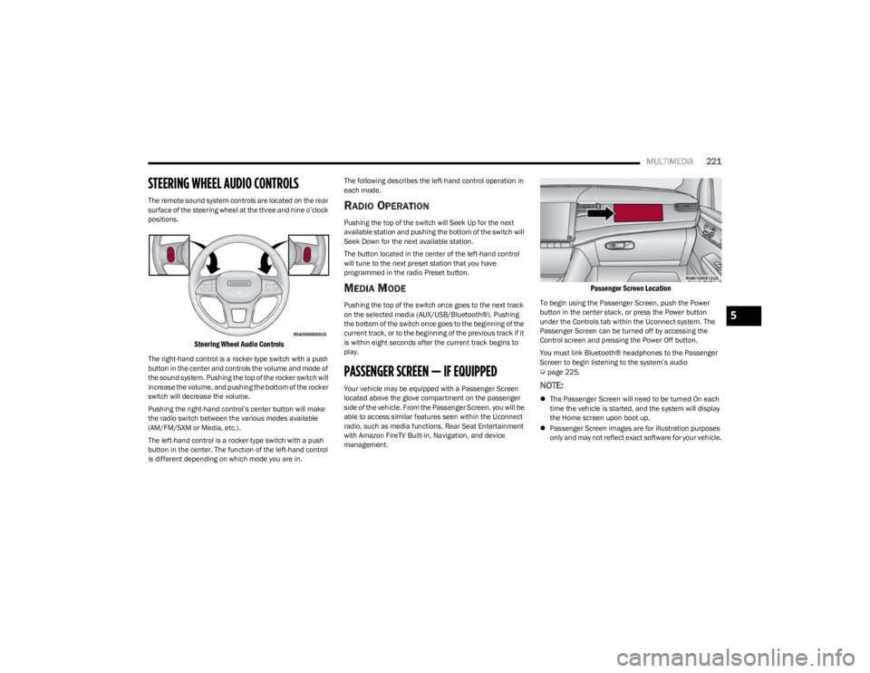
STEERING WHEEL AUDIO CONTROLS
The remote sound system controls are located on the rear
surface of the steering wheel at the three and nine o’clock
positions.
Steering Wheel Audio Controls
The right-hand control is a rocker-type switch with a push
button in the center and controls the volume and mode of
the sound system. Pushing the top of the rocker switch will
increase the volume, and pushing the bottom of the rocker
switch will decrease the volume.
Pushing the right-hand control’s center button will make
the radio switch between the various modes available
(AM/FM/SXM or Media, etc.).
The left-hand control is a rocker-type switch with a push
button in the center. The function of the left-hand control
is different depending on which mode you are in. The following describes the left-hand control operation in
each mode.
RADIO OPERATION
Pushing the top of the switch will Seek Up for the next
available station and pushing the bottom of the switch will
Seek Down for the next available station.
The button located in the center of the left-hand control
will tune to the next preset station that you have
programmed in the radio Preset button.
MEDIA MODE
Pushing the top of the switch once goes to the next track
on the selected media (AUX/USB/Bluetooth®). Pushing
the bottom of the switch once goes to the beginning of the
current track, or to the beginning of the previous track if it
is within eight seconds after the current track begins to
play.
PASSENGER SCREEN — IF EQUIPPED
Your vehicle may be equipped with a Passenger Screen
located above the glove compartment on the passenger
side of the vehicle. From the Passenger Screen, you will be
able to access similar features seen within the Uconnect
radio, such as media functions, Rear Seat Entertainment
with Amazon FireTV Built-in, Navigation, and device
management.
Passenger Screen Location
To begin using the Passenger Screen, push the Power
button in the center stack, or press the Power button
under the Controls tab within the Uconnect system. The
Passenger Screen can be turned off by accessing the
Control screen and pressing the Power Off button.
You must link Bluetooth® headphones to the Passenger
Screen to begin listening to the system’s audio
Úpage 225.
NOTE:
The Passenger Screen will need to be turned On each
time the vehicle is started, and the system will display
the Home screen upon boot up.
Passenger Screen images are for illustration purposes
only and may not reflect exact software for your vehicle.
5
23_WS_OM_EN_USC_t.book Page 221
Page 298 of 396
296IN CASE OF EMERGENCY
(Continued)
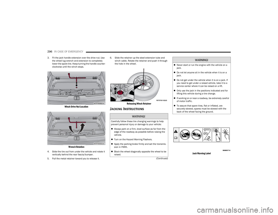
3. Fit the jack handle extension over the drive nut. Use
the wheel lug wrench and extension to completely
lower the spare tire. Keep turning the handle counter -
clockwise until the winch stops.
Winch Drive Nut Location
Wrench Rotation
4. Slide the tire out from under the vehicle and rotate it vertically behind the rear fascia/bumper.
5. Pull the metal retainer toward you to release it. 6. Slide the retainer up the steel extension tube and
winch cable. Rotate the retainer and push it through
the hole in the wheel.
Releasing Winch Retainer
JACKING INSTRUCTIONS
Jack Warning Label
WARNING!
Carefully follow these tire changing warnings to help
prevent personal injury or damage to your vehicle:
Always park on a firm, level surface as far from the
edge of the roadway as possible before raising the
vehicle.
Turn on the Hazard Warning Flashers.
Apply the parking brake firmly and set the transmis -
sion in PARK.
Block the wheel diagonally opposite the wheel to be
raised.
Never start or run the engine with the vehicle on a
jack.
Do not let anyone sit in the vehicle when it is on a
jack.
Do not get under the vehicle when it is on a jack. If
you need to get under a raised vehicle, take it to a
service center where it can be raised on a lift.
Only use the jack in the positions indicated and for
lifting this vehicle during a tire change.
If working on or near a roadway, be extremely careful
of motor traffic.
To assure that spare tires, flat or inflated, are
securely stowed, spares must be stowed with the
back of the wheel facing the ground.
WARNING!
23_WS_OM_EN_USC_t.book Page 296
Page 299 of 396
IN CASE OF EMERGENCY297
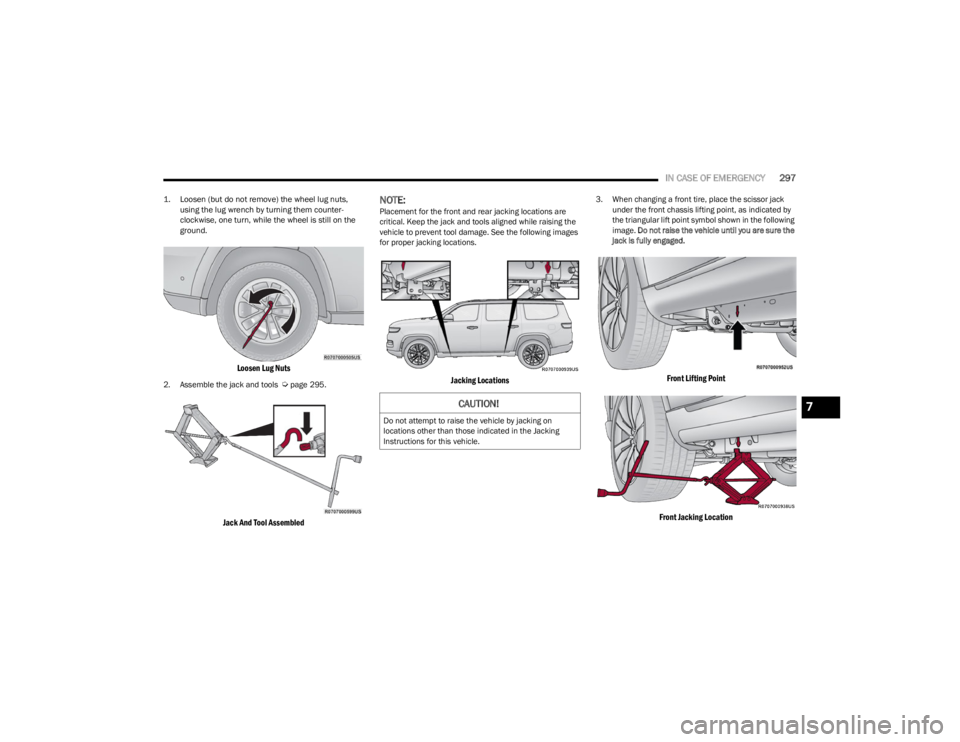
1. Loosen (but do not remove) the wheel lug nuts,
using the lug wrench by turning them counter -
clockwise, one turn, while the wheel is still on the
ground.
Loosen Lug Nuts
2. Assemble the jack and tools Úpage 295.
Jack And Tool Assembled
NOTE:Placement for the front and rear jacking locations are
critical. Keep the jack and tools aligned while raising the
vehicle to prevent tool damage. See the following images
for proper jacking locations.
Jacking Locations
3. When changing a front tire, place the scissor jack under the front chassis lifting point, as indicated by
the triangular lift point symbol shown in the following
image. Do not raise the vehicle until you are sure the
jack is fully engaged.
Front Lifting Point
Front Jacking Location
CAUTION!
Do not attempt to raise the vehicle by jacking on
locations other than those indicated in the Jacking
Instructions for this vehicle.
7
23_WS_OM_EN_USC_t.book Page 297
Page 300 of 396
298IN CASE OF EMERGENCY
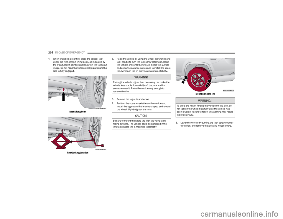
4. When changing a rear tire, place the scissor jack
under the rear chassis lifting point, as indicated by
the triangular lift point symbol shown in the following
image. Do not raise the vehicle until you are sure the
jack is fully engaged.
Rear Lifting Point
Rear Jacking Location
5. Raise the vehicle by using the wheel lug wrench and jack handle to turn the jack screw clockwise. Raise
the vehicle only until the tire just clears the surface
and enough clearance is obtained to install the spare
tire. Minimum tire lift provides maximum stability.
6. Remove the lug nuts and wheel.
7. Position the spare wheel/tire on the vehicle and install the lug nuts with the cone-shaped end toward
the wheel. Lightly tighten the nuts.
Mounting Spare Tire
8. Lower the vehicle by turning the jack screw counter -
clockwise, and remove the jack and wheel blocks.
WARNING!
Raising the vehicle higher than necessary can make the
vehicle less stable. It could slip off the jack and hurt
someone near it. Raise the vehicle only enough to
remove the tire.
CAUTION!
Be sure to mount the spare tire with the valve stem
facing outward. The vehicle could be damaged if the
inflatable spare tire is mounted incorrectly.
WARNING!
To avoid the risk of forcing the vehicle off the jack, do
not tighten the wheel nuts fully until the vehicle has
been lowered. Failure to follow this warning may result
in serious injury.
23_WS_OM_EN_USC_t.book Page 298
Page 301 of 396
IN CASE OF EMERGENCY299
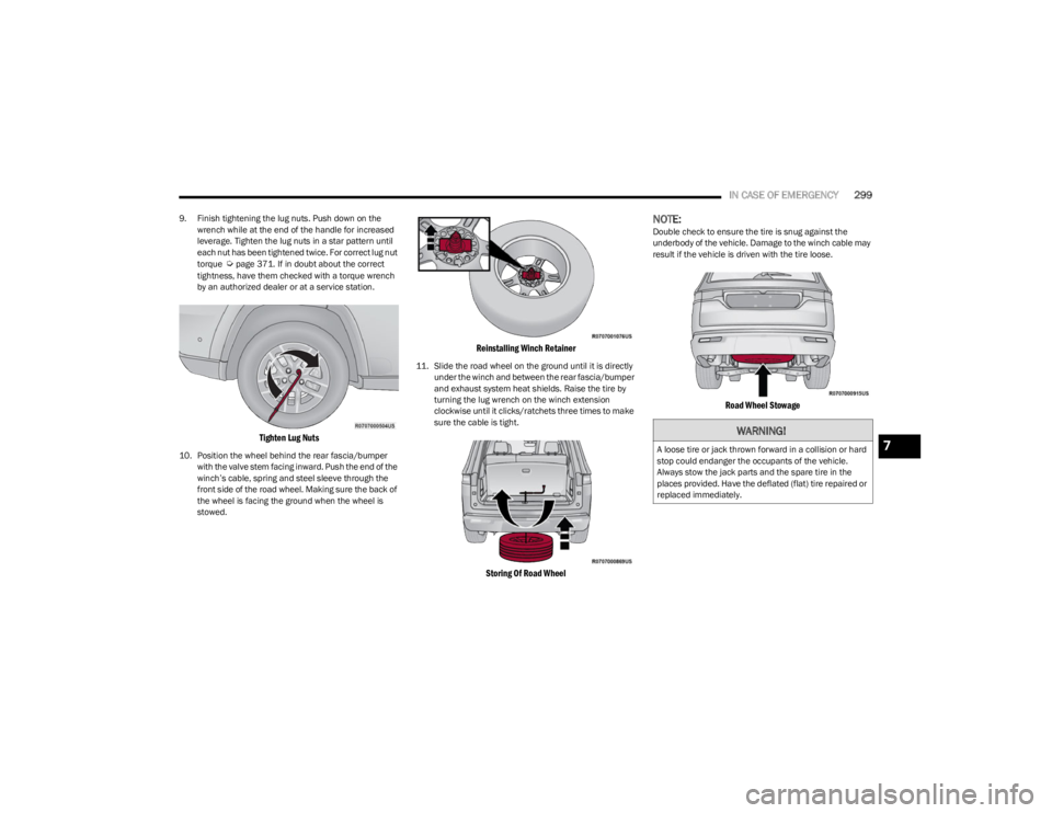
9. Finish tightening the lug nuts. Push down on the
wrench while at the end of the handle for increased
leverage. Tighten the lug nuts in a star pattern until
each nut has been tightened twice. For correct lug nut
torque
Úpage 371. If in doubt about the correct
tightness, have them checked with a torque wrench
by an authorized dealer or at a service station.
Tighten Lug Nuts
10. Position the wheel behind the rear fascia/bumper with the valve stem facing inward. Push the end of the
winch’s cable, spring and steel sleeve through the
front side of the road wheel. Making sure the back of
the wheel is facing the ground when the wheel is
stowed.
Reinstalling Winch Retainer
11. Slide the road wheel on the ground until it is directly under the winch and between the rear fascia/bumper
and exhaust system heat shields. Raise the tire by
turning the lug wrench on the winch extension
clockwise until it clicks/ratchets three times to make
sure the cable is tight.
Storing Of Road Wheel
NOTE:Double check to ensure the tire is snug against the
underbody of the vehicle. Damage to the winch cable may
result if the vehicle is driven with the tire loose.
Road Wheel Stowage
WARNING!
A loose tire or jack thrown forward in a collision or hard
stop could endanger the occupants of the vehicle.
Always stow the jack parts and the spare tire in the
places provided. Have the deflated (flat) tire repaired or
replaced immediately.7
23_WS_OM_EN_USC_t.book Page 299