headlamp JEEP WAGONEER 2023 Owners Manual
[x] Cancel search | Manufacturer: JEEP, Model Year: 2023, Model line: WAGONEER, Model: JEEP WAGONEER 2023Pages: 396, PDF Size: 15.17 MB
Page 125 of 396

STARTING AND OPERATING123
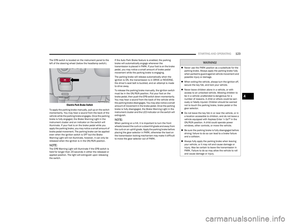
The EPB switch is located on the instrument panel to the
left of the steering wheel (below the headlamp switch).
Electric Park Brake Switch
To apply the parking brake manually, pull up on the switch
momentarily. You may hear a sound from the back of the
vehicle while the parking brake engages. Once the parking
brake is fully engaged, the Brake Warning Light in the
instrument cluster and an indicator on the switch will
illuminate. If your foot is on the brake pedal while you
apply the parking brake, you may notice a small amount of
brake pedal movement. The parking brake can be applied
even when the ignition switch is OFF but the Brake
Warning Light will not illuminate, however, it can only be
released when the ignition is in the ON/RUN position.
NOTE:The EPB Warning Light will illuminate if the EPB switch is
held for longer than 20 seconds in either the released or
applied position. The light will extinguish upon releasing
the switch. If the Auto Park Brake feature is enabled, the parking
brake will automatically engage whenever the
transmission is placed in PARK. If your foot is on the brake
pedal, you may notice a small amount of brake pedal
movement while the parking brake is engaging.
The parking brake will release automatically when the
ignition is ON, the transmission is in DRIVE or REVERSE,
the driver’s seat belt is buckled, and an attempt is made
to drive away.
To release the parking brake manually, the ignition switch
must be in the ON/RUN position. Put your foot on the
brake pedal, then push the EPB switch down momentarily.
You may hear a sound from the back of the vehicle while
the parking brake disengages. You may also notice a small
amount of movement in the brake pedal. Once the parking
brake is fully disengaged, the Brake Warning Light in the
instrument cluster and the LED indicator on the switch will
extinguish.
NOTE:When parking on a hill, it is important to turn the front
wheels toward the curb on a downhill grade and away from
the curb on an uphill grade. Apply the parking brake before
placing the gear selector in PARK, otherwise the load on
the transmission locking mechanism may make it difficult
to move the gear selector out of PARK.
WARNING!
Never use the PARK position as a substitute for the
parking brake. Always apply the parking brake fully
when parked to guard against vehicle movement and
possible injury or damage.
When exiting the vehicle, always turn the ignition off,
secure the key fob, and lock your vehicle.
Never leave children alone in a vehicle, or with
access to an unlocked vehicle. Allowing children to
be in a vehicle unattended is dangerous for a
number of reasons. A child or others could be seri -
ously or fatally injured. Children should be warned
not to touch the parking brake, brake pedal or the
gear selector.
Do not leave the key fob in or near the vehicle, or in
a location accessible to children, and do not leave a
vehicle equipped with Keyless Enter ‘n Go™ in the
ON/RUN position. A child could operate power
windows, other controls, or move the vehicle.
Be sure the parking brake is fully disengaged before
driving; failure to do so can lead to a brake failure
and a collision.
Always fully apply the parking brake when leaving
your vehicle, or it may roll and cause damage or
injury. Also be certain to leave the transmission in
PARK. Failure to do so may allow the vehicle to roll
and cause damage or injury.
4
23_WS_OM_EN_USC_t.book Page 123
Page 333 of 396

SERVICING AND MAINTENANCE331
FUSES
General Information
The fuses protect electrical systems against excessive
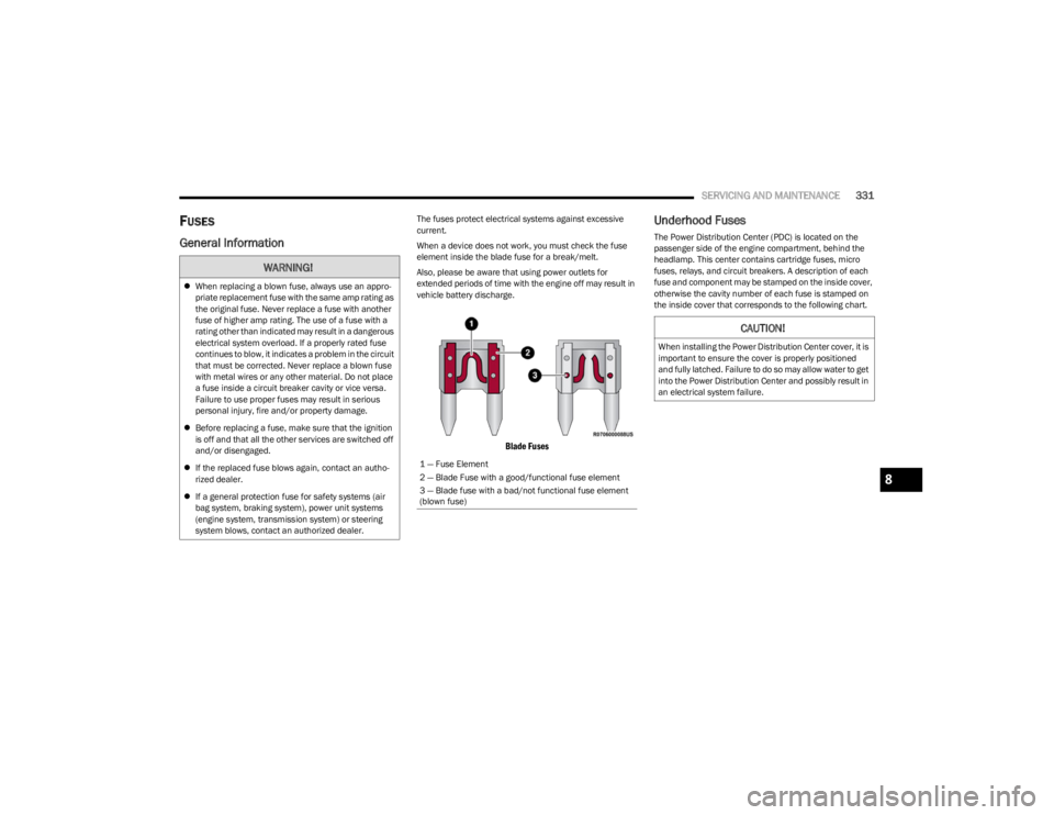
current.
When a device does not work, you must check the fuse
element inside the blade fuse for a break/melt.
Also, please be aware that using power outlets for
extended periods of time with the engine off may result in
vehicle battery discharge.
Blade Fuses
Underhood Fuses
The Power Distribution Center (PDC) is located on the
passenger side of the engine compartment, behind the
headlamp. This center contains cartridge fuses, micro
fuses, relays, and circuit breakers. A description of each
fuse and component may be stamped on the inside cover,
otherwise the cavity number of each fuse is stamped on
the inside cover that corresponds to the following chart.
WARNING!
When replacing a blown fuse, always use an appro -
priate replacement fuse with the same amp rating as
the original fuse. Never replace a fuse with another
fuse of higher amp rating. The use of a fuse with a
rating other than indicated may result in a dangerous
electrical system overload. If a properly rated fuse
continues to blow, it indicates a problem in the circuit
that must be corrected. Never replace a blown fuse
with metal wires or any other material. Do not place
a fuse inside a circuit breaker cavity or vice versa.
Failure to use proper fuses may result in serious
personal injury, fire and/or property damage.
Before replacing a fuse, make sure that the ignition
is off and that all the other services are switched off
and/or disengaged.
If the replaced fuse blows again, contact an autho -
rized dealer.
If a general protection fuse for safety systems (air
bag system, braking system), power unit systems
(engine system, transmission system) or steering
system blows, contact an authorized dealer.
1 — Fuse Element
2 — Blade Fuse with a good/functional fuse element
3 — Blade fuse with a bad/not functional fuse element
(blown fuse)
CAUTION!
When installing the Power Distribution Center cover, it is
important to ensure the cover is properly positioned
and fully latched. Failure to do so may allow water to get
into the Power Distribution Center and possibly result in
an electrical system failure.
8
23_WS_OM_EN_USC_t.book Page 331
Page 337 of 396

SERVICING AND MAINTENANCE335
F46 –5 Amp TanBatt Snsr #2*
F47 –10 Amp RedBPCM
F48 –10 Amp RedCVPAM
F49 –30 Amp PinkAir Suspension Valves
F50 ––Spare
F51 –20 Amp Yellow Fuel Pmp * / FPCM *
F52 ––Spare
F53 ––Spare
F54 –20 Amp Yellow Headlamp LT
F55 ––Spare
F56 ––Spare
F57 ––Spare
F58 ––Spare
F59 50 Amp Red –Air Suspension
F60 ––Spare
F61 ––Spare
F62 ––Spare
F63 –20 Amp Yellow Camera Washer Frt
F64 ––Spare
F65 –15 Amp BlueACT Grille Shutter / ACT Air Dam / Coolant Valve LCVM * / RATVM
F66 –20 Amp Yellow Horns
F67 –10 Amp RedDTCM / Switchable Engine Mount / BSM #2
Cavity Cartridge Fuse Micro Fuse Description
* If Equipped
8
23_WS_OM_EN_USC_t.book Page 335
Page 338 of 396

336SERVICING AND MAINTENANCE
F68 –20 Amp Yellow Headlamp RT
F69 ––Spare
F70 –20 Amp Yellow IGN Coil * / IGN Cap */ Fuel Inj */ ISCM *
F71 ––Spare
F72 ––Spare
F73 ––Spare
F74 –5 Amp TanMGU *
F75 30 Amp Pink –Front Wiper
F76 ––Spare
F77 –20 Amp Yellow TCM SBW
F78 –20 Amp Yellow Short Runner Valve / ECM
F79 –15 Amp RedFuel INJ * / Surge Solenoid * / Oil Sensor * / Air Valve * /
OBD Bypass * / O2 Heaters *
F80 20 Amp Blue –ECM
F81 40 Amp Green –BCM Feed #4
F82 ––Spare
F83 ––Spare
F84 ––Spare
F85 –10 Amp RedPCR *
F86 50 Amp Red –BSM Feed 1
F87 ––Spare
F88 50 Amp Red –BSM Feed 2
Cavity Cartridge Fuse Micro Fuse Description
* If Equipped
23_WS_OM_EN_USC_t.book Page 336