reset JEEP WAGONEER 2023 Owners Manual
[x] Cancel search | Manufacturer: JEEP, Model Year: 2023, Model line: WAGONEER, Model: JEEP WAGONEER 2023Pages: 396, PDF Size: 15.17 MB
Page 5 of 396
3
EXTERIOR LIGHTS ..............................................................57Headlight Switch ........................................................ 57
Multifunction Lever ..................................................... 58
Daytime Running Lights (DRLs) ................................. 58
High/Low Beam Switch .............................................. 58
Automatic High Beams — If Equipped ....................... 58
Flash-To-Pass ............................................................ 58
Automatic Headlights ................................................ 58
Parking Lights And Panel Lights................................. 59
Headlights On Automatically With Wipers ................. 59
Headlight Illumination On Approach .......................... 59
Headlight Delay ........................................................... 59
Lights-On Reminder .................................................... 59
Fog Lights .................................................................... 60
Turn Signals................................................................. 60
Lane Change Assist — If Equipped............................. 60
Battery Saver ............................................................... 60
INTERIOR LIGHTS ...............................................................60 Courtesy Lights............................................................ 60
Illuminated Entry — If Equipped ................................. 62
WINDSHIELD WIPERS AND WASHERS ........................... 62 Windshield Wiper Operation....................................... 62
Rain Sensing Wipers — If Equipped .......................... 63
Rear Wiper And Washer ............................................ 64
Windshield Wiper De-Icer — If Equipped ................... 64
CLIMATE CONTROLS ..........................................................64 Automatic Climate Control Descriptions And
Functions ..................................................................... 64
Automatic Temperature Control (ATC) ....................... 71
Climate Voice Recognition.......................................... 71
Operating Tips ............................................................ 71 INTERIOR STORAGE AND EQUIPMENT ............................ 73
Storage ......................................................................... 73
Center Console Cooler —
If Equipped ................................................................... 75
Center Console Safe — If Equipped ............................ 75
Sun Screens — If Equipped ......................................... 76
USB/AUX Control ......................................................... 76
Electrical Power Outlets ..............................................79
Power Inverter ............................................................. 80
Wireless Charging Pad — If Equipped......................... 81
WINDOWS .......................................................................... 82 Power Window Controls............................................... 82
Wind Buffeting ............................................................ 83
Radio Signal Devices On Windshield —
If Equipped ................................................................... 83
POWER SUNROOF — IF EQUIPPED................................... 83 Tri-Pane Power Sunroof............................................... 83
HOOD.................................................................................... 85 Opening The Hood .......................................................85
Closing The Hood ......................................................... 86
LIFTGATE .............................................................................. 86 To Unlock/Open The Liftgate ......................................86
To Lock/Close The Liftgate ......................................... 86
Adjustable Power Liftgate Height ............................... 87
Hands-Free Liftgate .................................................... 87
Cargo Area Features ................................................... 89
ROOF LUGGAGE RACK — IF EQUIPPED ........................... 91 Installing The Crossbars ..............................................91
Removing The Crossbars ............................................ 95GETTING TO KNOW YOUR
INSTRUMENT PANEL
BASE INSTRUMENT CLUSTER .......................................... 96 Instrument Cluster Descriptions ................................ 97
PREMIUM INSTRUMENT CLUSTER .................................. 98 Instrument Cluster Descriptions ................................ 99
INSTRUMENT CLUSTER DISPLAY ..................................... 99 Location And Controls ................................................. 99
Engine Oil Life Reset ................................................ 101
Display And Messages .............................................. 102Instrument Cluster Display Menu Items ................. 104Head Up Display (HUD) — If Equipped ..................... 106
Battery Saver On/Battery Saver Mode
Message — Electrical Load Reduction
Actions (If Equipped) ................................................ 107
WARNING LIGHTS AND MESSAGES ..............................108 Red Warning Lights ................................................... 109
Yellow Warning Lights ............................................... 111Yellow Indicator Lights .............................................. 114Green Indicator Lights............................................... 115White Indicator Lights ............................................... 116Blue Indicator Lights ................................................. 117
Gray Indicator Lights ................................................. 117
ONBOARD DIAGNOSTIC SYSTEM — OBD II ................... 117 Onboard Diagnostic System
(OBD II) Cybersecurity ............................................... 118
EMISSIONS INSPECTION AND MAINTENANCE
PROGRAMS ......................................................................118
23_WS_OM_EN_USC_t.book Page 3
Page 26 of 396
24GETTING TO KNOW YOUR VEHICLE
REMOTE START ABORT MESSAGE
One of the following messages will display in the
instrument cluster display if the vehicle fails to remote
start or exits Remote Start prematurely:
Remote Start Canceled — Door Open
Remote Start Canceled — Hood Open
Remote Start Canceled — Liftgate Open
Remote Start Canceled — Fuel Low
Remote Start Canceled — System Fault
Remote Start Disabled — Start Vehicle to Reset
The instrument cluster display message stays active until
the ignition is placed in the ON/RUN position.
VEHICLE SECURITY SYSTEM — IF EQUIPPED
The Vehicle Security system monitors the vehicle doors,
hood, liftgate, and the Keyless Enter ‘n Go™ Ignition for
unauthorized operation. While the Vehicle Security system
is armed, interior switches for door locks and liftgate
release handle are disabled. If something triggers the
alarm, the Vehicle Security system will provide the
following audible and visible signals:
The horn will pulse
The turn signals will flash
The Vehicle Security Light in the instrument cluster
will flash
TO ARM THE SYSTEM
Follow these steps to arm the Vehicle Security system:
1. Make sure the vehicle’s ignition is placed in the OFF
position.
For vehicles equipped with Keyless Entry, make
sure the vehicle’s keyless ignition system is OFF.
2. Perform one of the following methods to lock the vehicle:
Push lock on the interior power door lock switch
with the driver and/or passenger door open.
Touch the lock button on the exterior Passive Entry
door handle with a valid key fob available in the
same exterior zone
Úpage 167.
Push the lock button on the key fob.
3. If any doors are open, close them.
When the Vehicle Security system is armed, the Vehicle
Security Light (located in the lower right portion of the
instrument cluster display) will begin to flash every two
seconds until it is disarmed.
NOTE:If the system is armed by pushing the lock button on the
interior door panel, the Vehicle Security Light will flash
rapidly for about 15 seconds once the door is closed, then
slow down to every two seconds.
TO DISARM THE SYSTEM
The Vehicle Security system can be disarmed using any of
the following methods:
Push the unlock button on the key fob.
Grab the Passive Entry door handle to unlock the door
Úpage 167.
Cycle the ignition out of the OFF position to disarm the
system.
NOTE:
The driver's door key cylinder cannot arm or disarm the
Vehicle Security system. Use of the door key cylinder
when the alarm is armed will sound the alarm when the
door is opened.
The Vehicle Security system remains armed when the
power liftgate is opened using the liftgate button on the
key fob. If someone enters the vehicle through the
opened liftgate, then opens any door from the inside,
the alarm will sound.
If Passive Entry (if equipped) is used to unlock the lift -
gate, the Vehicle Security system is disarmed and the
rest of the vehicle doors will remain locked unless all
doors are set to unlock on first press within Uconnect
Settings.
When the Vehicle Security system is armed, the interior
power door lock switches will not unlock the doors.
23_WS_OM_EN_USC_t.book Page 24
Page 33 of 396
GETTING TO KNOW YOUR VEHICLE31
Use the four-way control to adjust the steering column.
NOTE:For vehicles equipped with Driver Memory Settings, use
the key fob or the memory switch on the driver's door trim
panel to return the tilt/telescopic steering column to
saved positions
Úpage 31.
HEATED STEERING WHEEL
The steering wheel contains a heating element
that helps warm your hands in cold weather.
The heated steering wheel has three
temperature settings. Once the heated
steering wheel has been turned on, it will stay on until the
operator turns it off. The heated steering wheel may not
turn on when it is already warm. The heated steering wheel control button is located on the
left side of the radio screen or within the Uconnect system.
You can gain access to the control button on the top left
side of the screen by tapping the temperature controls,
which will provide a quick drop-down menu containing the
controls, or through the controls screen of the
touchscreen. If your vehicle is not equipped with the
button on the side of the radio, you can also access the
control button through the climate screen.
Press the heated steering wheel button once to turn
the HI setting on.
Press the heated steering wheel button a second time
to turn the MED setting on.
Press the heated steering wheel button a third time to
turn the LO setting on.
Press the heated steering wheel button a fourth time to
turn the heating elements off.NOTE:The engine must be running for the heated steering wheel
to operate.
For information on use with the Remote Start system, see
Úpage 23.
DRIVER AND PASSENGER MEMORY
SETTINGS — IF EQUIPPED
This feature allows the driver, and if equipped, also the
front passenger to save up to two different memory
profiles for easy recall through a memory switch. Each
memory profile saves desired position settings for the
following features:
Driver’s Side
Seat position
Easy entry/exit seat (if equipped)
Side mirrors
Power tilt and telescopic steering column (if equipped)
Power adjustable pedals (if equipped)
A set of desired radio station presets
WARNING!
Do not adjust the steering column while driving.
Adjusting the steering column while driving or driving
with the steering column unlocked, could cause the
driver to lose control of the vehicle. Failure to follow this
warning may result in serious injury or death.
WARNING!
Persons who are unable to feel pain to the skin
because of advanced age, chronic illness, diabetes,
spinal cord injury, medication, alcohol use, exhaus -
tion, or other physical conditions must exercise care
when using the steering wheel heater. It may cause
burns even at low temperatures, especially if used
for long periods.
Do not place anything on the steering wheel that
insulates against heat, such as a blanket or steering
wheel covers of any type and material. This may
cause the steering wheel heater to overheat.
2
23_WS_OM_EN_USC_t.book Page 31
Page 34 of 396
32GETTING TO KNOW YOUR VEHICLE
Passenger’s Side (If Equipped)
Seat position
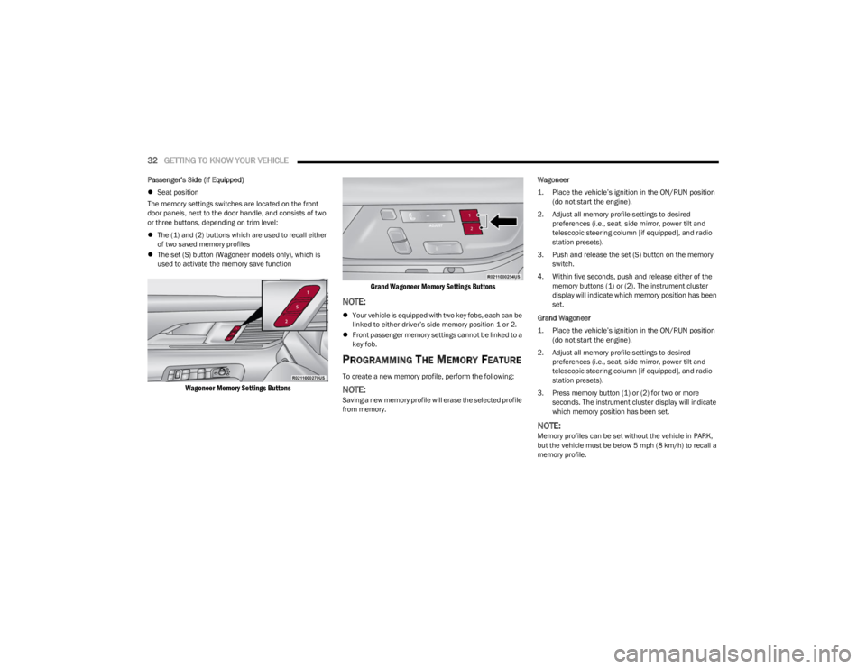
The memory settings switches are located on the front
door panels, next to the door handle, and consists of two
or three buttons, depending on trim level:
The (1) and (2) buttons which are used to recall either
of two saved memory profiles
The set (S) button (Wagoneer models only), which is
used to activate the memory save function
Wagoneer Memory Settings Buttons Grand Wagoneer Memory Settings Buttons
NOTE:
Your vehicle is equipped with two key fobs, each can be
linked to either driver’s side memory position 1 or 2.
Front passenger memory settings cannot be linked to a
key fob.
PROGRAMMING THE MEMORY FEATURE
To create a new memory profile, perform the following:
NOTE:Saving a new memory profile will erase the selected profile
from memory. Wagoneer
1. Place the vehicle’s ignition in the ON/RUN position
(do not start the engine).
2. Adjust all memory profile settings to desired preferences (i.e., seat, side mirror, power tilt and
telescopic steering column [if equipped], and radio
station presets).
3. Push and release the set (S) button on the memory switch.
4. Within five seconds, push and release either of the memory buttons (1) or (2). The instrument cluster
display will indicate which memory position has been
set.
Grand Wagoneer
1. Place the vehicle’s ignition in the ON/RUN position (do not start the engine).
2. Adjust all memory profile settings to desired preferences (i.e., seat, side mirror, power tilt and
telescopic steering column [if equipped], and radio
station presets).
3. Press memory button (1) or (2) for two or more seconds. The instrument cluster display will indicate
which memory position has been set.
NOTE:Memory profiles can be set without the vehicle in PARK,
but the vehicle must be below 5 mph (8 km/h) to recall a
memory profile.
23_WS_OM_EN_USC_t.book Page 32
Page 45 of 396
GETTING TO KNOW YOUR VEHICLE43
(Continued)
The massage type and intensity level status will be
synchronized between the main Uconnect display and the
Front Comfort and Convenience Display.
The selected settings will save in the system’s memory
when turned off, and will resume the next time the system
is turned on.
NOTE:
For vehicles equipped with a selectable back/cushion
feature for massage seats, the massage feature can
be deselected for either the seatback or seat cushion.
If both options are deselected, massage will turn off.
The engine must be running for the power seatback
massage to operate.
The massage feature will turn off after 20 minutes of
use. However, if the massage type or intensity level is
changed, the timer then resets.
HEATED SEATS — IF EQUIPPED
Front Heated Seats
The front heated seats control buttons are
located on the sides of the radio or within the
Uconnect system. You can access the controls
through the Climate screen.
Press the heated seat button once to turn the HI setting
on.
Press the heated seat button a second time to turn the
MED setting on.
Press the heated seat button a third time to turn the
LO setting on.
Press the heated seat button a fourth time to turn the
heating elements off.
The heating elements can be turned on in the seatback
only, seat cushion only, or both. Press the seat image on
the touchscreen or push the seat zone button on the side
of the radio to cycle through these seat zones. An LED will
illuminate next to the selected zone(s). If equipped with
touchscreen buttons, the selected zones will be
highlighted on the seat image.
NOTE:
Once a heat setting is selected, heat will be felt within
two to five minutes.
The engine must be running for the heated seats to
operate.
The level of heat selected will stay on until the operator
changes it.
For information on use with the Remote Start system, see
Úpage 23.
Rear Heated Seats — If Equipped
The two second row outboard seats may be
equipped with heated seats. There are two
heated seat switches that allow the rear
passengers to operate the seats
independently. The heated seat switches for each heater
are located on the rear of the center console.
If equipped with a Rear Comfort And Convenience Display,
heated seat settings can be selected within the display
Úpage 69.
You can choose from HI, MED, LO, or OFF heat settings.
Indicator lights in each switch illuminate indicating the
level of heat in use.
Push the heated seat switch once to turn the HI setting
on.
Push the heated seat switch a second time to turn the
MED setting on.
Push the heated seat switch a third time to turn the
LO setting on.
Push the heated seat switch a fourth time to turn the
heating elements off.WARNING!
Persons who are unable to feel pain to the skin
because of advanced age, chronic illness, diabetes,
spinal cord injury, medication, alcohol use, exhaus -
tion or other physical condition must exercise care
when using the seat heater. It may cause burns even
at low temperatures, especially if used for long
periods of time.
Do not place anything on the seat or seatback that
insulates against heat, such as a blanket or cushion.
This may cause the seat heater to overheat. Sitting in
a seat that has been overheated could cause serious
burns due to the increased surface temperature of
the seat.
WARNING!
2
23_WS_OM_EN_USC_t.book Page 43
Page 54 of 396
52GETTING TO KNOW YOUR VEHICLE
POWER MIRRORS
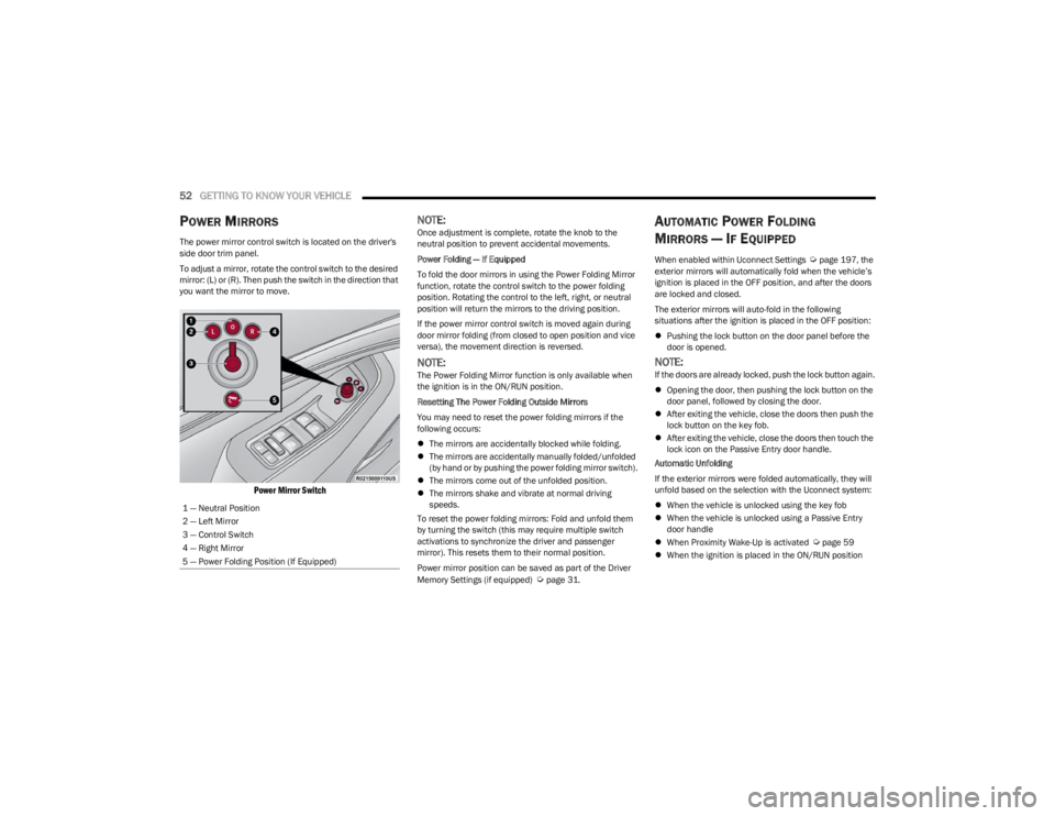
The power mirror control switch is located on the driver's
side door trim panel.
To adjust a mirror, rotate the control switch to the desired
mirror: (L) or (R). Then push the switch in the direction that
you want the mirror to move.
Power Mirror Switch
NOTE:Once adjustment is complete, rotate the knob to the
neutral position to prevent accidental movements.
Power Folding — If Equipped
To fold the door mirrors in using the Power Folding Mirror
function, rotate the control switch to the power folding
position. Rotating the control to the left, right, or neutral
position will return the mirrors to the driving position.
If the power mirror control switch is moved again during
door mirror folding (from closed to open position and vice
versa), the movement direction is reversed.
NOTE:The Power Folding Mirror function is only available when
the ignition is in the ON/RUN position.
Resetting The Power Folding Outside Mirrors
You may need to reset the power folding mirrors if the
following occurs:
The mirrors are accidentally blocked while folding.
The mirrors are accidentally manually folded/unfolded
(by hand or by pushing the power folding mirror switch).
The mirrors come out of the unfolded position.
The mirrors shake and vibrate at normal driving
speeds.
To reset the power folding mirrors: Fold and unfold them
by turning the switch (this may require multiple switch
activations to synchronize the driver and passenger
mirror). This resets them to their normal position.
Power mirror position can be saved as part of the Driver
Memory Settings (if equipped)
Úpage 31.
AUTOMATIC POWER FOLDING
M
IRRORS — IF EQUIPPED
When enabled within Uconnect Settings Úpage 197, the
exterior mirrors will automatically fold when the vehicle’s
ignition is placed in the OFF position, and after the doors
are locked and closed.
The exterior mirrors will auto-fold in the following
situations after the ignition is placed in the OFF position:
Pushing the lock button on the door panel before the
door is opened.
NOTE:If the doors are already locked, push the lock button again.
Opening the door, then pushing the lock button on the
door panel, followed by closing the door.
After exiting the vehicle, close the doors then push the
lock button on the key fob.
After exiting the vehicle, close the doors then touch the
lock icon on the Passive Entry door handle.
Automatic Unfolding
If the exterior mirrors were folded automatically, they will
unfold based on the selection with the Uconnect system:
When the vehicle is unlocked using the key fob
When the vehicle is unlocked using a Passive Entry
door handle
When Proximity Wake-Up is activated
Úpage 59
When the ignition is placed in the ON/RUN position
1 — Neutral Position
2 — Left Mirror
3 — Control Switch
4 — Right Mirror
5 — Power Folding Position (If Equipped)
23_WS_OM_EN_USC_t.book Page 52
Page 78 of 396
76GETTING TO KNOW YOUR VEHICLE
The keypad will then turn red again, and return to the
locked mode when the safe lid is closed.
NOTE:The keypad will flash red if an incorrect lock code is
entered. If the incorrect code is entered ten times in a row,
the user will be locked out from further attempts for
approximately 30 minutes.
To revert the safe back to the unlocked mode:
1. Enter the programmed 6-digit code.
2. Press and hold the Door Open button for two
seconds. The keypad will flash red and change to
pink.
3. Enter the 6-digit code and press the Door Open button. The keypad will flash white.
Once this procedure is completed, the safe will no longer
lock when the lid is closed.
Lock Code Override
If you forget the 6-digit code, there is a way to override the
code, using the emergency key stored inside your key fob:
1. Remove the emergency key from the key fob
Ú
page 18.
2. Use the emergency key to open the safe door.
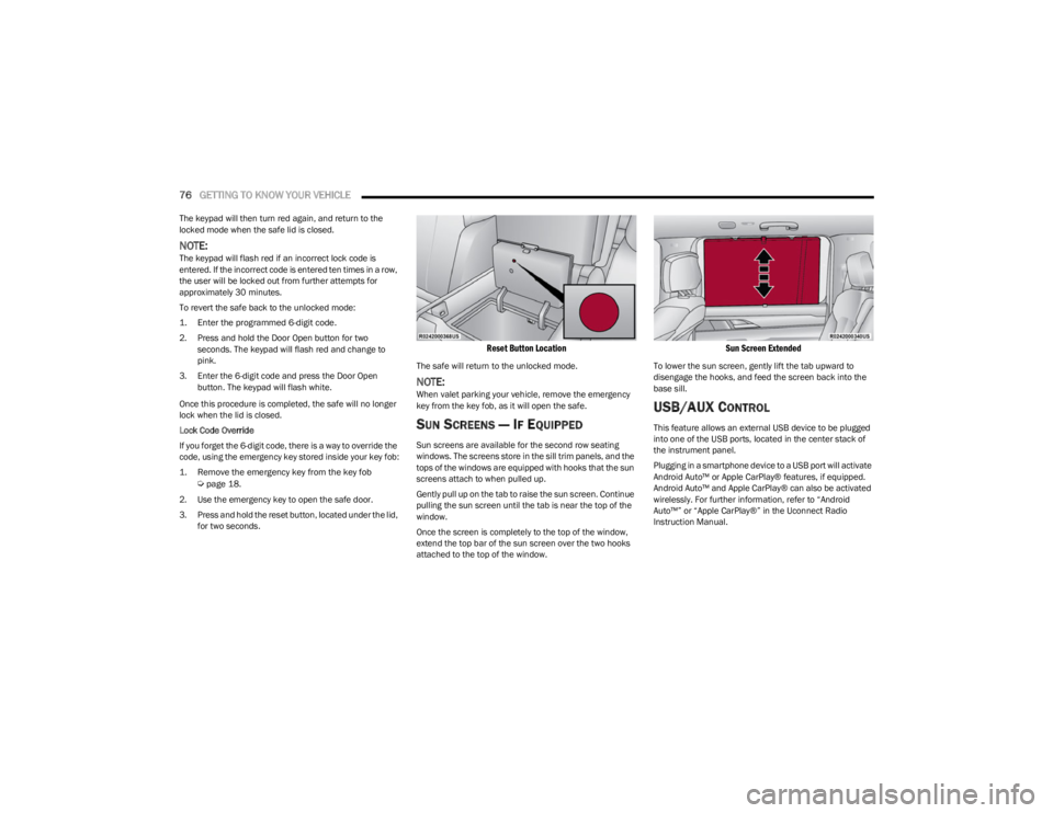
3. Press and hold the reset button, located under the lid, for two seconds.
Reset Button Location
The safe will return to the unlocked mode.
NOTE:When valet parking your vehicle, remove the emergency
key from the key fob, as it will open the safe.
SUN SCREENS — IF EQUIPPED
Sun screens are available for the second row seating
windows. The screens store in the sill trim panels, and the
tops of the windows are equipped with hooks that the sun
screens attach to when pulled up.
Gently pull up on the tab to raise the sun screen. Continue
pulling the sun screen until the tab is near the top of the
window.
Once the screen is completely to the top of the window,
extend the top bar of the sun screen over the two hooks
attached to the top of the window.
Sun Screen Extended
To lower the sun screen, gently lift the tab upward to
disengage the hooks, and feed the screen back into the
base sill.
USB/AUX CONTROL
This feature allows an external USB device to be plugged
into one of the USB ports, located in the center stack of
the instrument panel.
Plugging in a smartphone device to a USB port will activate
Android Auto™ or Apple CarPlay® features, if equipped.
Android Auto™ and Apple CarPlay® can also be activated
wirelessly. For further information, refer to “Android
Auto™” or “Apple CarPlay®” in the Uconnect Radio
Instruction Manual.
23_WS_OM_EN_USC_t.book Page 76
Page 82 of 396
80GETTING TO KNOW YOUR VEHICLE
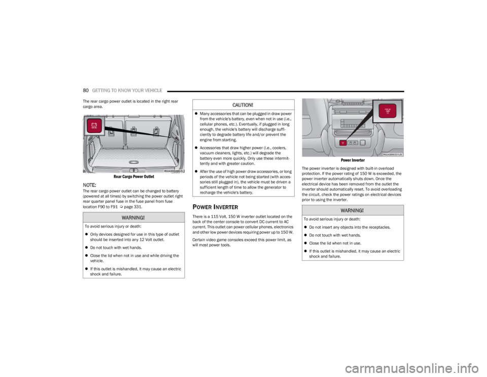
The rear cargo power outlet is located in the right rear
cargo area.
Rear Cargo Power Outlet
NOTE:The rear cargo power outlet can be changed to battery
(powered at all times) by switching the power outlet right
rear quarter panel fuse in the fuse panel from fuse
location F90 to F91
Úpage 331.POWER INVERTER
There is a 115 Volt, 150 W inverter outlet located on the
back of the center console to convert DC current to AC
current. This outlet can power cellular phones, electronics
and other low power devices requiring power up to 150 W.
Certain video game consoles exceed this power limit, as
will most power tools.
Power Inverter
The power inverter is designed with built-in overload
protection. If the power rating of 150 W is exceeded, the
power inverter automatically shuts down. Once the
electrical device has been removed from the outlet the
inverter should automatically reset. To avoid overloading
the circuit, check the power ratings on electrical devices
prior to using the inverter.
WARNING!
To avoid serious injury or death:
Only devices designed for use in this type of outlet
should be inserted into any 12 Volt outlet.
Do not touch with wet hands.
Close the lid when not in use and while driving the
vehicle.
If this outlet is mishandled, it may cause an electric
shock and failure.
CAUTION!
Many accessories that can be plugged in draw power
from the vehicle's battery, even when not in use (i.e.,
cellular phones, etc.). Eventually, if plugged in long
enough, the vehicle's battery will discharge suffi -
ciently to degrade battery life and/or prevent the
engine from starting.
Accessories that draw higher power (i.e., coolers,
vacuum cleaners, lights, etc.) will degrade the
battery even more quickly. Only use these intermit -
tently and with greater caution.
After the use of high power draw accessories, or long
periods of the vehicle not being started (with acces -
sories still plugged in), the vehicle must be driven a
sufficient length of time to allow the generator to
recharge the vehicle's battery.
WARNING!
To avoid serious injury or death:
Do not insert any objects into the receptacles.
Do not touch with wet hands.
Close the lid when not in use.
If this outlet is mishandled, it may cause an electric
shock and failure.
23_WS_OM_EN_USC_t.book Page 80
Page 84 of 396
82GETTING TO KNOW YOUR VEHICLE
WINDOWS
POWER WINDOW CONTROLS
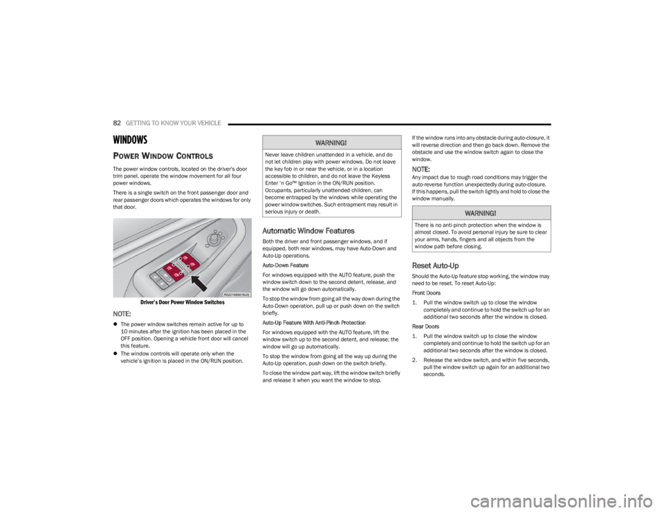
The power window controls, located on the driver's door
trim panel, operate the window movement for all four
power windows.
There is a single switch on the front passenger door and
rear passenger doors which operates the windows for only
that door.
Driver’s Door Power Window Switches
NOTE:
The power window switches remain active for up to
10 minutes after the ignition has been placed in the
OFF position. Opening a vehicle front door will cancel
this feature.
The window controls will operate only when the
vehicle’s ignition is placed in the ON/RUN position.
Automatic Window Features
Both the driver and front passenger windows, and if
equipped, both rear windows, may have Auto-Down and
Auto-Up operations.
Auto-Down Feature
For windows equipped with the AUTO feature, push the
window switch down to the second detent, release, and
the window will go down automatically.
To stop the window from going all the way down during the
Auto-Down operation, pull up or push down on the switch
briefly.
Auto-Up Feature With Anti-Pinch Protection
For windows equipped with the AUTO feature, lift the
window switch up to the second detent, and release; the
window will go up automatically.
To stop the window from going all the way up during the
Auto-Up operation, push down on the switch briefly.
To close the window part way, lift the window switch briefly
and release it when you want the window to stop. If the window runs into any obstacle during auto-closure, it
will reverse direction and then go back down. Remove the
obstacle and use the window switch again to close the
window.
NOTE:Any impact due to rough road conditions may trigger the
auto-reverse function unexpectedly during auto-closure.
If this happens, pull the switch lightly and hold to close the
window manually.
Reset Auto-Up
Should the Auto-Up feature stop working, the window may
need to be reset. To reset Auto-Up:
Front Doors
1. Pull the window switch up to close the window
completely and continue to hold the switch up for an
additional two seconds after the window is closed.
Rear Doors
1. Pull the window switch up to close the window completely and continue to hold the switch up for an
additional two seconds after the window is closed.
2. Release the window switch, and within five seconds, pull the window switch up again for an additional two
seconds.
WARNING!
Never leave children unattended in a vehicle, and do
not let children play with power windows. Do not leave
the key fob in or near the vehicle, or in a location
accessible to children, and do not leave the Keyless
Enter ‘n Go™ Ignition in the ON/RUN position.
Occupants, particularly unattended children, can
become entrapped by the windows while operating the
power window switches. Such entrapment may result in
serious injury or death.
WARNING!
There is no anti-pinch protection when the window is
almost closed. To avoid personal injury be sure to clear
your arms, hands, fingers and all objects from the
window path before closing.
23_WS_OM_EN_USC_t.book Page 82
Page 89 of 396
GETTING TO KNOW YOUR VEHICLE87
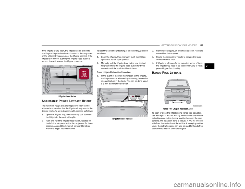
If the liftgate is fully open, the liftgate can be closed by
pushing the liftgate close button located in the cargo area
on the left rear trim panel, near the liftgate opening. If the
liftgate is in motion, pushing the liftgate close button a
second time will reverse the liftgate operation.
Liftgate Close Button
ADJUSTABLE POWER LIFTGATE HEIGHT
The maximum height that the liftgate will open can be
adjusted and saved so that the liftgate will only open to the
desired height. To set a desired height, proceed as follows:
1. Open the liftgate fully, then manually pull down on
the liftgate to the desired height.
2. Push and hold the liftgate close button, located on the left side trim panel inside the cargo area, for three
seconds. An audible chime will be heard to let you
know the height has been saved. To reset the saved height setting to a new setting, proceed
as follows:
1. Open the liftgate, then manually push the liftgate
upward to its full open position.
2. Manually pull the liftgate down to the new desired height and hold the liftgate close button for three
seconds until the audible chime is heard.
Power Liftgate Malfunction Procedure:
1. In the event of a power malfunction to the liftgate, the liftgate can be released by accessing the service
release feature in the latch. This can be done using
a 3 mm diameter screwdriver.
Liftgate Service Release
2. From inside the gate, an eyelet can be seen. Place the screwdriver in the eyelet.
3. Rotate the screwdriver handle to actuate the lever and release the latch.
4. If liftgate is left open for an extended period of time, the liftgate may need to be closed manually to reset
power liftgate functionality.
HANDS-FREE LIFTGATE
Hands-Free Liftgate Activation Zone
To open or close the liftgate using hands-free activation,
use a straight in and out kicking motion under the vehicle
activation zone in the general location between the park
sensors. The activation zone is about 1 ft (0.3 m) on each
side from the centerline of the vehicle. A sweeping motion
under the activation zone can also be used for hands-free
activation to open or close the liftgate.
2
23_WS_OM_EN_USC_t.book Page 87