tow bar JEEP WAGONEER 2023 Owners Manual
[x] Cancel search | Manufacturer: JEEP, Model Year: 2023, Model line: WAGONEER, Model: JEEP WAGONEER 2023Pages: 396, PDF Size: 15.17 MB
Page 7 of 396

5
SURROUND VIEW CAMERA SYSTEM —
IF EQUIPPED ..................................................................... 175Zoom View ................................................................. 176
REFUELING THE VEHICLE .............................................. 177
VEHICLE LOADING ........................................................ 178 Gross Vehicle Weight Rating (GVWR) ..................... 178
Payload ...................................................................... 178
Gross Axle Weight Rating (GAWR)............................ 178
Tire Size ..................................................................... 178Rim Size ..................................................................... 178Inflation Pressure ...................................................... 178Curb Weight ............................................................... 178
Loading ...................................................................... 178
TRAILER TOWING............................................................. 178 Common Towing Definitions .................................... 179
Trailer Hitch Classification........................................ 182Trailer Towing Weights (Maximum Trailer
Weight Ratings) ......................................................... 182
Trailer Hitch Receiver Cover Removal —
If Equipped ................................................................ 184
Trailer And Tongue Weight ...................................... 185
Towing Requirements .............................................. 185
Towing Tips ............................................................... 189
RECREATIONAL TOWING (BEHIND MOTORHOME) ..... 190 Towing This Vehicle Behind Another Vehicle .......... 190
Recreational Towing — Two-Wheel
Drive Models ............................................................. 190Recreational Towing — Quadra-Trac I
(Single-Speed Transfer Case) Four-Wheel
Drive Models ............................................................. 191Recreational Towing — Quadra–Trac II/
Quadra–Drive II Four-Wheel Drive Models .............. 191
DRIVING TIPS ................................................................... 193 On-Road Driving Tips ................................................ 193Off-Road Driving Tips ................................................ 193MULTIMEDIA
UCONNECT SYSTEMS ..................................................... 196
CYBERSECURITY ............................................................. 196
UCONNECT SETTINGS ..................................................... 197 Customer Programmable Features ......................... 197
STEERING WHEEL AUDIO CONTROLS .......................... 221 Radio Operation ........................................................ 221Media Mode .............................................................. 221
PASSENGER SCREEN — IF EQUIPPED .......................... 221 Passenger Screen Permissions ............................... 222
Home Screen ............................................................ 222
Audio And Video ........................................................ 223Rear Seat Entertainment with Amazon Fire TV
Built-in — If Equipped................................................ 224
HDMI Projecting ........................................................ 225Device Manager........................................................ 225Navigation ................................................................. 226Camera ...................................................................... 226
3RD PARTY APPS — IF EQUIPPED ................................ 226
REAR SEAT ENTERTAINMENT (RSE) WITH
AMAZON FIRE TV BUILT-IN — IF EQUIPPED.................. 228 Overview .................................................................... 228
Getting Started.......................................................... 228
Accessing Rear Seat Entertainment with
Fire TV built-in from the Front Radio Screen........... 228
Accessing Rear Seat Entertainment with
Fire TV built-in from the Rear Screens .................... 229
Accessing Rear Seat Entertainment with
Fire TV built-in from the Passenger Screen —
If Equipped ................................................................ 229 First Time Starting Up
(Using the Rear Screens) .......................................... 229
Alexa Voice Control.................................................... 230
Listen Via Vehicle Speakers ..................................... 230
Quick Menu................................................................ 230
Parental Controls (Using the Rear Screens) ............ 230
Voice Remote with Alexa Pairing
(Using the Rear Screens) .......................................... 230
Media Sources Input (Using the Front Radio
and Rear Screens)..................................................... 230
Voice Remote with Alexa........................................... 231
Replacing the Voice Remote with
Alexa Batteries........................................................... 231
Rear Seat Entertainment with Fire TV Built-In
streaming (Using the Front Radio and
Rear Screens) ............................................................ 232Fire TV Apps/Games
(Using the Rear Screens) .......................................... 233
Are We There Yet? ..................................................... 233Using The Video USB Port ......................................... 233
Play Video Games...................................................... 233Headphones Operation ............................................. 233
Rear Climate Controls ............................................... 234Legal & Compliance .................................................. 235
OFF-ROAD PAGES — IF EQUIPPED .................................236 Off-Road Pages Status Bar ....................................... 236Vehicle Dynamics ...................................................... 236Accessory Gauges ..................................................... 237Pitch & Roll ................................................................ 237
Selec-Terrain — If Equipped ...................................... 237Suspension — If Equipped ........................................ 238
RADIO OPERATION AND MOBILE PHONES ..................238 Regulatory And Safety Information .......................... 238
23_WS_OM_EN_USC_t.book Page 5
Page 42 of 396
40GETTING TO KNOW YOUR VEHICLE
When either the (+) or the (–) switch is pushed, the Front
Comfort And Convenience Display Úpage 64 will change
to the Seat menu. The last selected seat item of lumbar
in/out, lumbar up/down, back bolster, or thigh bolster will
be retained. Select the desired adjustment type, and then
press the (+) or (–) switch to adjust.
NOTE:If the Front Comfort And Convenience Display is in the
stowed position, the Seat menu will appear in the main
Uconnect display.
Cushion Extender — If Equipped
In Grand Wagoneer models, the cushion can be extended
forward a couple inches (centimeters) to increase thigh
support. Push the cushion extender switch forward or
rearward to extend or retract the cushion. Release the
switch when the desired position has been reached.
Power Lumbar — If Equipped
The front driver and passenger seats may be equipped
with power lumbar adjustment.
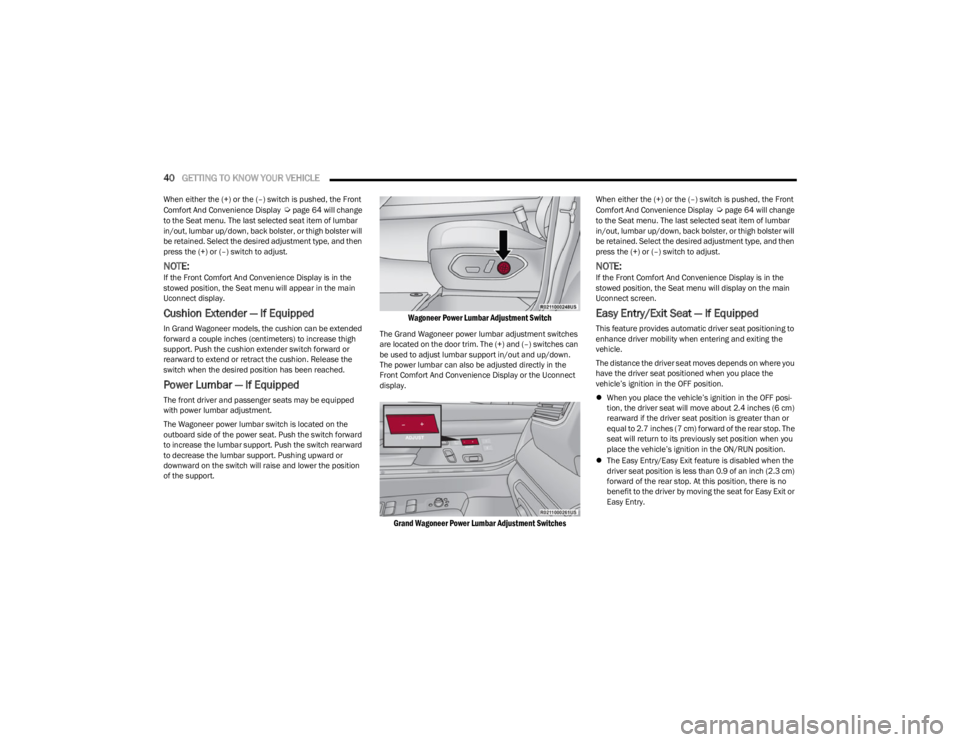
The Wagoneer power lumbar switch is located on the
outboard side of the power seat. Push the switch forward
to increase the lumbar support. Push the switch rearward
to decrease the lumbar support. Pushing upward or
downward on the switch will raise and lower the position
of the support.
Wagoneer Power Lumbar Adjustment Switch
The Grand Wagoneer power lumbar adjustment switches
are located on the door trim. The (+) and (–) switches can
be used to adjust lumbar support in/out and up/down.
The power lumbar can also be adjusted directly in the
Front Comfort And Convenience Display or the Uconnect
display.
Grand Wagoneer Power Lumbar Adjustment Switches
When either the (+) or the (–) switch is pushed, the Front
Comfort And Convenience Display Úpage 64 will change
to the Seat menu. The last selected seat item of lumbar
in/out, lumbar up/down, back bolster, or thigh bolster will
be retained. Select the desired adjustment type, and then
press the (+) or (–) switch to adjust.
NOTE:If the Front Comfort And Convenience Display is in the
stowed position, the Seat menu will display on the main
Uconnect screen.
Easy Entry/Exit Seat — If Equipped
This feature provides automatic driver seat positioning to
enhance driver mobility when entering and exiting the
vehicle.
The distance the driver seat moves depends on where you
have the driver seat positioned when you place the
vehicle’s ignition in the OFF position.
When you place the vehicle’s ignition in the OFF posi -
tion, the driver seat will move about 2.4 inches (6 cm)
rearward if the driver seat position is greater than or
equal to 2.7 inches (7 cm) forward of the rear stop. The
seat will return to its previously set position when you
place the vehicle’s ignition in the ON/RUN position.
The Easy Entry/Easy Exit feature is disabled when the
driver seat position is less than 0.9 of an inch (2.3 cm)
forward of the rear stop. At this position, there is no
benefit to the driver by moving the seat for Easy Exit or
Easy Entry.
23_WS_OM_EN_USC_t.book Page 40
Page 68 of 396
66GETTING TO KNOW YOUR VEHICLE
MAX Defrost Button
Press the MAX Defrost button on the
touchscreen, or push the toggle switch on the
faceplate down, to change the current airflow
setting to Defrost mode. The indicator
illuminates when this feature is on. Performing this
function will cause the automatic climate controls to
change to manual mode.
When MAX Defrost mode is selected:
The blower speed increases to full (all LEDs on)
Air conditioning compressor is turned on (LED on)
Both driver and passenger temperature controls are
set to HI
Defrost mode is selected (LED on)
Rear defroster is turned on (LED on)
Air recirculation is turned off (LED off)
If MAX Defrost mode is turned off, the Climate Control
system will return to the previous setting.
Rear Defrost Button
Press and release the button on the
touchscreen, or push the toggle switch on the
faceplate down, to turn on the rear window
defroster and the heated outside mirrors (if
equipped). The Rear Defrost indicator illuminates when
the rear window defroster is on. The rear window defroster
automatically turns off after 10 minutes.
Driver And Passenger Temperature
Switches
These toggle switches provide the driver and passenger
with independent temperature control by pushing the
single switch upward or downward.
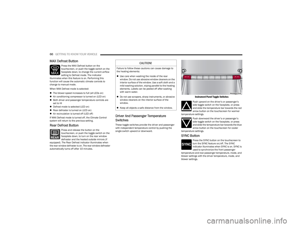
Instrument Panel Toggle Switches
Push upward on the driver’s or passenger’s
side toggle switch on the faceplate, or press
and slide the temperature bar towards the red
arrow button on the touchscreen for warmer
temperature settings.
Push downward the driver’s or passenger’s
side toggle switch on the faceplate, or press
and slide the temperature bar towards the blue
arrow button on the touchscreen for cooler
temperature settings.
SYNC Button
Press the SYNC button on the touchscreen to
turn the SYNC feature on/off. The SYNC
indicator illuminates when SYNC is on. SYNC is
used to synchronize the front passenger
temperature and rear passenger temperature, mode, and
blower settings with the driver temperature, mode, and
blower settings.
CAUTION!
Failure to follow these cautions can cause damage to
the heating elements:
Use care when washing the inside of the rear
window. Do not use abrasive window cleaners on the
interior surface of the window. Use a soft cloth and a
mild washing solution, wiping parallel to the heating
elements. Labels can be peeled off after soaking
with warm water.
Do not use scrapers, sharp instruments, or abrasive
window cleaners on the interior surface of the
window.
Keep all objects a safe distance from the window.
23_WS_OM_EN_USC_t.book Page 66
Page 72 of 396
70GETTING TO KNOW YOUR VEHICLE
AUTO BUTTON
Push the AUTO button below the rear climate
control display, or if equipped, press and
release the AUTO button on the Rear Comfort
And Convenience Display touchscreen to
control the rear passenger area’s temperature by
automatically adjusting distribution and amount of airflow.
Performing this function will cause the system to switch
between manual mode and automatic modes
Úpage 71.
REAR TEMPERATURE CONTROL
Push the Up or Down buttons near the rear climate control
display, or if equipped, press the Up or Down arrow
buttons on the Rear Comfort And Convenience Display
touchscreen to control the rear passenger’s temperature.
NOTE:If equipped with a Four-Zone ATC system, the left and right
sides of the rear passenger zones can be adjusted sepa -
rately.
Push the Up arrow hard button, or press and
release, or slide the temperature bar on the
touchscreen towards the red arrow button on
the touchscreen for warmer temperature
settings.
Push the Down arrow hard button, or press and
release, or slide the temperature bar on the
touchscreen towards the blue arrow button on
the touchscreen for cooler temperature
settings.
REAR BLOWER CONTROL
Blower Control is used to regulate the amount
of air forced through the Climate Control
system. There are several blower speeds
available. The speeds can be selected using
the blower control buttons near the rear climate control
display, or if equipped, on the Rear Comfort And
Convenience Display touchscreen.
Use the blower button with the down arrow, or small
blower icon on the touchscreen to reduce the blower
setting. Use the blower button with the up arrow, or the
large blower icon on the touchscreen to increase the
blower setting.
NOTE:Blower speed can also be selected by pressing the
numbered blower speed on the touchscreen bar area
between the blower icons.
REAR MODE CONTROL
Pushing the Mode button below the rear
climate control display, located on the rear of
the center console, will cycle through the three
rear mode control options for airflow
distribution. These options are: Face, Face/Feet, and
Feet.
Mode Control From The Rear Comfort And Convenience
Display
If equipped with the Rear Comfort And Convenience
display, two airflow distribution modes can be selected
on/off from the display by individually by pressing the icons on the touchscreen for up to three combinations of
airflow. The icons on the screen will illuminate when
selected, and turn off when deselected.
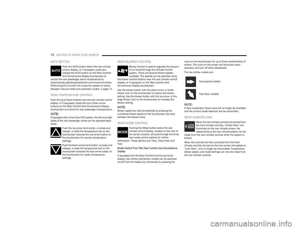
The two airflow modes are:
NOTE:If Auto is selected, these icons will no longer be available
and the current mode selection will be overwritten.
REAR CLIMATE LOCK
When the rear climate controls are locked from
the front climate controls, “Unlock Rear” will
illuminate on the rear climate screen. No
adjustments to the rear climate system can be
made from the rear climate controls while the system is
locked.
When the controls are then unlocked from the front
climate controls, the text on the rear screen will update to
“Lock Rear”, and no longer be illuminated. Temperature,
blower speed, and mode settings can now be made from
the rear climate controls.
Face (panel outlets)
Feet (floor outlets)
23_WS_OM_EN_USC_t.book Page 70
Page 93 of 396
GETTING TO KNOW YOUR VEHICLE91
Retractable Cargo Area Cover —
If Equipped
The purpose of this cover is for privacy, not to secure
loads. It will not prevent cargo from shifting or protect
passengers from loose cargo.
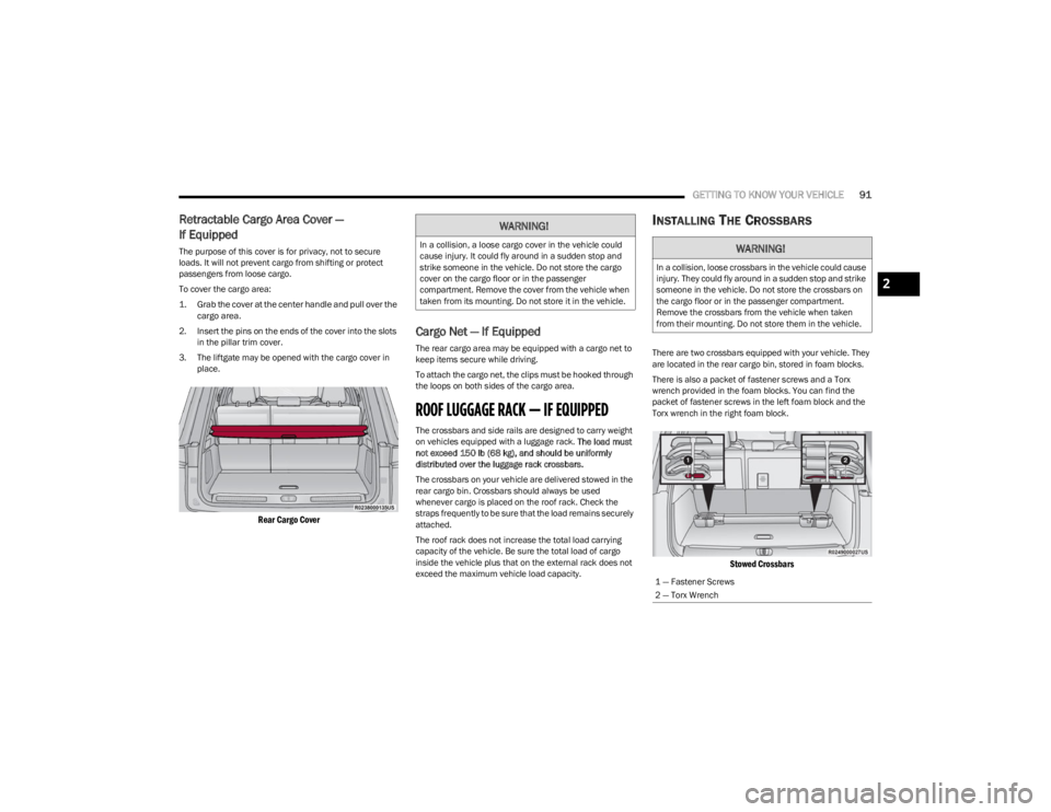
To cover the cargo area:
1. Grab the cover at the center handle and pull over the
cargo area.
2. Insert the pins on the ends of the cover into the slots in the pillar trim cover.
3. The liftgate may be opened with the cargo cover in place.
Rear Cargo Cover
Cargo Net — If Equipped
The rear cargo area may be equipped with a cargo net to
keep items secure while driving.
To attach the cargo net, the clips must be hooked through
the loops on both sides of the cargo area.
ROOF LUGGAGE RACK — IF EQUIPPED
The crossbars and side rails are designed to carry weight
on vehicles equipped with a luggage rack. The load must
not exceed 150 lb (68 kg), and should be uniformly
distributed over the luggage rack crossbars.
The crossbars on your vehicle are delivered stowed in the
rear cargo bin. Crossbars should always be used
whenever cargo is placed on the roof rack. Check the
straps frequently to be sure that the load remains securely
attached.
The roof rack does not increase the total load carrying
capacity of the vehicle. Be sure the total load of cargo
inside the vehicle plus that on the external rack does not
exceed the maximum vehicle load capacity.
INSTALLING THE CROSSBARS
There are two crossbars equipped with your vehicle. They
are located in the rear cargo bin, stored in foam blocks.
There is also a packet of fastener screws and a Torx
wrench provided in the foam blocks. You can find the
packet of fastener screws in the left foam block and the
Torx wrench in the right foam block.
Stowed Crossbars
WARNING!
In a collision, a loose cargo cover in the vehicle could
cause injury. It could fly around in a sudden stop and
strike someone in the vehicle. Do not store the cargo
cover on the cargo floor or in the passenger
compartment. Remove the cover from the vehicle when
taken from its mounting. Do not store it in the vehicle.WARNING!
In a collision, loose crossbars in the vehicle could cause
injury. They could fly around in a sudden stop and strike
someone in the vehicle. Do not store the crossbars on
the cargo floor or in the passenger compartment.
Remove the crossbars from the vehicle when taken
from their mounting. Do not store them in the vehicle.
1 — Fastener Screws
2 — Torx Wrench
2
23_WS_OM_EN_USC_t.book Page 91
Page 94 of 396
92GETTING TO KNOW YOUR VEHICLE
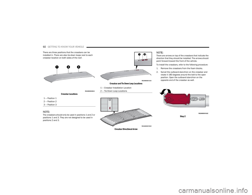
There are three positions that the crossbars can be
installed in. There are also tie-down loops next to each
crossbar location on both sides of the roof.
Crossbar Locations
NOTE:The crossbars should only be used in positions 1 and 2 or
positions 1 and 3. They are not designed to be used in
positions 2 and 3.
Crossbar and Tie Down Loop Locations
Crossbar Directional Arrow
NOTE:There are arrows on top of the crossbars that indicate the
direction that they should be installed. The arrows should
point forward toward the front of the vehicle.
To install the crossbars, refer to the following procedure:
1. Remove the crossbars from the foam blocks.
2. Swivel the outboard stanchion on the crossbar and rotate it 180 degrees around the bolt to the open
position. Open the outboard stanchion on the
opposite end of the crossbar as well.
Step 2
1 — Position 1
2 — Position 2
3 — Position 3
1 — Crossbar Installation Location
2 — Tie-Down Loop Locations
23_WS_OM_EN_USC_t.book Page 92
Page 97 of 396
GETTING TO KNOW YOUR VEHICLE95
REMOVING THE CROSSBARS
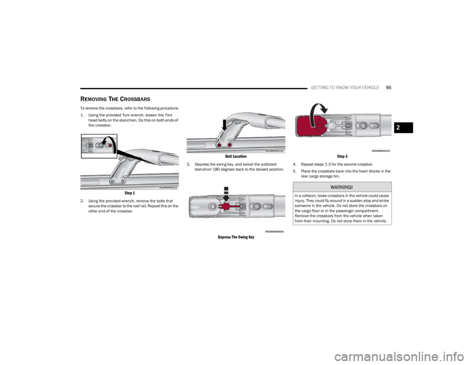
To remove the crossbars, refer to the following procedure:
1. Using the provided Torx wrench, loosen the Torx
head bolts on the stanchion. Do this on both ends of
the crossbar.
Step 1
2. Using the provided wrench, remove the bolts that secure the crossbar to the roof rail. Repeat this on the
other end of the crossbar.
Bolt Location
3. Depress the swing key, and swivel the outboard stanchion 180 degrees back to the stowed position.
Depress The Swing Key Step 3
4. Repeat steps 1-3 for the second crossbar.
5. Place the crossbars back into the foam blocks in the
rear cargo storage bin.
WARNING!
In a collision, loose crossbars in the vehicle could cause
injury. They could fly around in a sudden stop and strike
someone in the vehicle. Do not store the crossbars on
the cargo floor or in the passenger compartment.
Remove the crossbars from the vehicle when taken
from their mounting. Do not store them in the vehicle.
2
23_WS_OM_EN_USC_t.book Page 95
Page 181 of 396
STARTING AND OPERATING179
COMMON TOWING DEFINITIONS
The following trailer towing related definitions will assist
you in understanding the following information:
Gross Vehicle Weight Rating (GVWR)
The GVWR is the total allowable weight of your vehicle.
This includes driver, passengers, cargo and tongue
weight. The total load must be limited so that you do not
exceed the GVWR
Úpage 178.
Gross Trailer Weight (GTW)
The GTW is the weight of the trailer plus the weight of all
cargo, consumables and equipment (permanent or
temporary) loaded in or on the trailer in its "loaded and
ready for operation" condition.
The recommended way to measure GTW is to put your fully
loaded trailer on a vehicle scale. The entire weight of the
trailer must be supported by the scale.
Gross Combination Weight Rating (GCWR)
The GCWR is the total allowable weight of your vehicle and
trailer when weighed in combination.
Gross Axle Weight Rating (GAWR)
The GAWR is the maximum capacity of the front and rear
axles. Distribute the load over the front and rear axles
evenly. Make sure that you do not exceed either front or
rear GAWR
Úpage 178.
Tongue Weight (TW)
The TW is the downward force exerted on the hitch ball by
the trailer. You must consider this as part of the load on
your vehicle.
Trailer Frontal Area
The frontal area is the maximum height multiplied by the
maximum width of the front of a trailer.
Trailer Sway Control (TSC)
The TSC can be a mechanical telescoping link that can be
installed between the hitch receiver and the trailer tongue
that typically provides adjustable friction associated with
the telescoping motion to dampen any unwanted trailer
swaying motions while traveling.
If equipped, the electronic TSC recognizes a swaying
trailer and automatically applies individual wheel brakes
and/or reduces engine power to attempt to eliminate the
trailer sway.
Weight-Carrying Hitch
A weight-carrying hitch supports the trailer tongue weight,
just as if it were luggage located at a hitch ball or some
other connecting point of the vehicle. These kinds of
hitches are used to tow small and medium sized trailers.
Weight-Distributing Hitch
A Weight-Distributing Hitch system works by applying
leverage through spring (load) bars. They are typically
used for heavier loads to distribute trailer tongue weight to
the tow vehicle's front axle and the trailer axle(s). When
used in accordance with the manufacturer's directions, it
provides for a more level ride, offering more consistent
steering and brake control thereby enhancing towing
safety. The addition of a friction/hydraulic sway control
also dampens sway caused by traffic and crosswinds and
contributes positively to tow vehicle and trailer stability.
Trailer sway control and a weight-distributing (load
equalizing) hitch are recommended for heavier Tongue
Weights (TW) and may be required depending on vehicle
and trailer configuration/loading to comply with Gross Axle
Weight Rating (GAWR) requirements.
WARNING!
If the gross trailer weight is 5,000 lb (2,267 kg) or
more, it is recommended to use a weight-distributing
hitch to ensure stable handling of your vehicle. If you
use a standard weight-carrying hitch, you could lose
control of your vehicle and cause a collision.
WARNING!
It is important that you do not exceed the maximum
front or rear GAWR. A dangerous driving condition can
result if either rating is exceeded. You could lose control
of the vehicle and have a collision.
WARNING!
An improperly adjusted Weight-Distributing Hitch
system may reduce handling, stability, braking
performance, and could result in a collision.
Weight-Distributing Hitch systems may not be
compatible with surge brake couplers. Consult with
your hitch and trailer manufacturer or a reputable
Recreational Vehicle dealer for additional
information.
4
23_WS_OM_EN_USC_t.book Page 179
Page 182 of 396
180STARTING AND OPERATING
RECOMMENDED DISTRIBUTION HITCH
ADJUSTMENT — QUADRA-LIFT AIR SUSPEN -
SION EQUIPPED VEHICLES
1. Verify that the vehicle is at the Normal Ride Height.
NOTE:The vehicle must remain in the RUN position with all doors
closed while attaching a trailer for proper leveling of the air
suspension system.
2. Position the vehicle on a level surface in preparation to connect to the trailer (do not connect the trailer).
3. For vehicles equipped with Quadra-Lift air suspension, use the touchscreen radio settings to
enable Tire/Jack mode. Tire/Jack mode will be
canceled and the procedure must be restarted if the
vehicle is driven at speeds above 5 mph (8 km/h).
When towing, the automatic Entry/Exit feature may
be disabled through the Uconnect Touchscreen Radio
to prevent vehicle and trailer movement when gear
selector is moved to PARK.
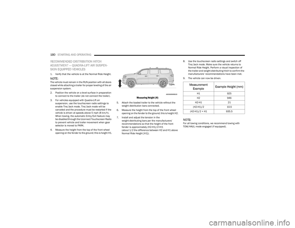
4. Measure the height from the top of the front wheel opening on the fender to the ground; this is height H1.
Measuring Height (H)
5. Attach the loaded trailer to the vehicle without the weight distribution bars connected.
6. Measure the height from the top of the front wheel opening on the fender to the ground; this is height H2.
7. Install and adjust the tension in the weight-distributing bars per the manufacturers’
recommendations so that the height of the front
fender is approximately (H2-H1)/2+H1
(about 1/2 the difference between H2 and H1 above
Normal Ride Height [H1]). 8. Use the touchscreen radio settings and switch off
Tire/Jack mode. Make sure the vehicle returns to
Normal Ride Height. Perform a visual inspection of
the trailer and weight-distributing hitch to confirm the
manufacturers’ recommendations have been met.
9. The vehicle can now be driven.
NOTE:For all towing conditions, we recommend towing with
TOW/HAUL mode engaged (if equipped).
Measurement Example Example Height (mm)
H1
925
H2 946
H2-H1 21
(H2-H1)/2 10.5
(H2-H1)/2 + H1 935.5
23_WS_OM_EN_USC_t.book Page 180
Page 183 of 396
STARTING AND OPERATING181
RECOMMENDED DISTRIBUTION HITCH
ADJUSTMENT — NON-AIR SUSPENSION
EQUIPPED VEHICLES
1. Verify that the vehicle is at the normal ride height.
2. Position the vehicle on a level surface in preparation
to connect to the trailer (do not connect the trailer).
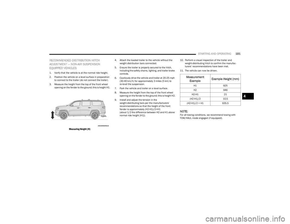
3. Measure the height from the top of the front wheel opening on the fender to the ground; this is height H1.
Measuring Height (H)
4. Attach the loaded trailer to the vehicle without the weight distribution bars connected.
5. Ensure the trailer is properly secured to the hitch, including the safety chains, lighting, and trailer brake
controls.
6. Cautiously drive the vehicle and trailer at 20-25 mph (30-40 km/h) for approximately 3 miles (5 km) to
re-level the suspension.
7. Park the vehicle and trailer on a level surface.
8. Measure the height from the top of the front wheel opening on the fender to the ground; this is height H2.
9. Install and adjust the tension in the weight-distributing bars per the manufacturers’
recommendations so that the height of the front
fender is approximately (H2-H1)/2+H1
(about 1/2 the difference between H2 and H1 above
normal ride height [H1]). 10. Perform a visual inspection of the trailer and
weight-distributing hitch to confirm the manufac -
turers’ recommendations have been met.
11. The vehicle can now be driven.
NOTE:For all towing conditions, we recommend towing with
TOW/HAUL mode engaged (if equipped).
Measurement Example Example Height (mm)
H1
925
H2 946
H2-H1 21
(H2-H1)/2 10.5
(H2-H1)/2 + H1 935.5
4
23_WS_OM_EN_USC_t.book Page 181