check engine light JEEP WRANGLER 2004 TJ / 2.G Owners Manual
[x] Cancel search | Manufacturer: JEEP, Model Year: 2004, Model line: WRANGLER, Model: JEEP WRANGLER 2004 TJ / 2.GPages: 299, PDF Size: 6.82 MB
Page 12 of 299

Key-In-Ignition Reminder
Opening the driver's door when the key is in the ignition,
sounds a signal to remind you to remove the key.
CAUTION!
Always remove the key from the ignition, and lock
all doors when leaving the vehicle unattended.
SENTRY KEY IMMOBILIZER SYSTEM Ð IF
EQUIPPED
The Sentry Key Immobilizer System (SKIS) prevents
unauthorized operation of the vehicle by disabling the
engine. The system will shut the engine down after 2
seconds of running if an invalid key is used to start the
vehicle. This system utilizes ignition keys which have an
electronic chip (transponder) embedded into them. Only
keys that have been programmed to the vehicle can be
used to start and operate the vehicle for longer than the
2 second validation time period.
The Sentry Key Immobilizer System does not need to be
armed or activated. Operation of the system is automaticregardless of whether or not the vehicle is locked or
unlocked. During normal operation, the SKIS indicator
light will come on for 3 seconds immediately after the
ignition switch is turned on for a bulb check. Afterwards,
if the bulb remains on, this indicates a malfunction in the
electronics. If the bulb begins to flash immediately after
the ignition switch is turned on, this indicates that an
invalid key is being used to start the vehicle. Both of
these conditions will result in the engine being shut
down after 2 seconds of running. Keep in mind that a key
which has not been programmed is also considered an
invalid key even if it is cut to fit the ignition for that
vehicle.
If the SKIS indicator light comes on during normal
vehicle operation (it has been running for longer than 10
seconds) a fault has been detected in the electronics and
the vehicle should be serviced as soon as possible.
NOTE:
²
The Sentry Key Immobilizer System is not compatible
with remote starting systems. Use of these systems
may result in vehicle starting problems and loss of
security protection.
12 THINGS TO KNOW BEFORE STARTING YOUR VEHICLE
Page 58 of 299

Front Fog Lights Ð If Equipped
The front fog light switch is in the multi-function
control lever. To activate the front fog lights, turn
on the parking or low beam headlights and pull
out the end of the lever.
NOTE:The fog lights will only operate with the park-
ing lights or the headlights on low beam. Selecting high
beam headlights will turn off the fog lights.
Turn Signals
Move the multi-function control lever up or down and
the arrows on each side of the instrument cluster flash to
show proper operation of the front and rear turn signal
lights. You can signal a lane change by moving the lever
partially up or down without moving beyond the detent.
If either light remains on and does not flash, or there is a
very fast flash rate, check for a defective outside light
bulb. If an indicator fails to light when the lever is
moved, it would suggest that the fuse or indicator bulb is
defective.
NOTE:A tone will chime if the turn signals are left on
for more than 1 mile (2 km).
Daytime Running Lights Ð Canada Only
The headlights come on at a low intensity level after the
vehicle has been driven approximately 3 feet (1 meter).
They will turn off when the vehicle is turned off or when
the headlights are switched on.
WINDSHIELD WIPERS AND WASHERS
CAUTION!
In cold weather, always turn off the wiper switch
and allow the wipers to return to the park position
before turning off the engine. If the wiper switch is
left on and the wipers freeze to the windshield,
damage to the wiper motor may occur when the
vehicle is restarted.
Intermittent Wiper System
Use the intermittent wiper when weather conditions
make a single wiping cycle, with a variable pause be-
tween cycles, desirable. Move the lever to the DELAY
position, then select the delay interval by turning the end
58 UNDERSTANDING THE FEATURES OF YOUR VEHICLE
Page 118 of 299

15. Coolant Temperature Gauge
Indicates engine coolant temperature. The red
zone to the far right indicates possible overheat-
ing. Seek authorized service immediately if the
gauge operates in the red zone. In U.S. vehicles,
temperature is indicated in degrees fahrenheit; in
Canadian vehicles in degrees centigrade.
16. Airbag Warning Light
This indicator lights and remains lit for 6 to
8 seconds when the ignition is first turned
on. If the light does not come on for 6 to 8
seconds, stays on or comes on while driving,
have the airbag system checked by an authorized
dealer.
17. Check Gauges Warning Light
This light monitors the engine coolant tem-
perature, engine oil pressure, and voltage
gauges. If it detects an extreme condition a
chime will sound and the light will come on. If the
light comes on, check the operation of these gauges for
a malfunction condition.18. Malfunction Indicator Light
This light is a part of an Onboard Diagnostic
System called OBD II that monitors engine,
and automatic transmission control systems.
The light will illuminate when the ignition is in the
ON position before engine start. If the bulb does not
come on when turning the key from OFF to ON, have
the condition checked promptly.
Certain conditions such as a loose or missing gas cap,
poor quality fuel, etc. may illuminate the light after
engine start. The vehicle should be serviced if the light
stays on through several typical driving styles. In most
situations, the vehicle will drive normally and will not
require towing.
When the engine is running, the ªMalfunction Indicator
Lightº may flash to alert serious conditions that could
lead to immediate loss of power or severe catalytic
converter damage. The vehicle should be serviced as
soon as possible if this occurs.
118 UNDERSTANDING YOUR INSTRUMENT PANEL
Page 120 of 299

If the parking brake is applied and the vehicle is in
motion, the red BRAKE warning light will ªflashº and a
chime will sound.
The operation of the BRAKE warning light can be
checked by turning the ignition switch from the OFF
position to the ON position. The light should illuminate
for approximately two seconds. The light should then
turn off unless the parking brake is applied or a brake
fault is detected. If the light does not illuminate, have the
light inspected by an authorized dealer.
23. Low Fuel Warning Light
When the fuel level reaches approximately 2 U.S.
Gallons (7.6L) this light will come on and remain
on until fuel is added. The ªLow Fuel Warning
Lightº may turn on and off again, especially during
and after hard braking, accelerations, or turns. This
occurs due to the shifting of the fuel in the tank.
24. Fuel Cap Indicator
This symbol indicates the side of the vehicle
where the fuel cap is located.25. Fuel Gauge
The pointer shows the level of fuel in the fuel tank. When
the fuel gauge pointer initially moves to E, for your
safety, approximately 2 U.S. Gallons (7.6L) of fuel remain.
NOTE:When the ignition switch is turned to OFF, the
fuel gauge, voltmeter, oil pressure and temperature
gauges may not show accurate readings. When the
engine is not running, turn the ignition switch to ON to
obtain accurate readings.
ELECTRONIC DIGITAL CLOCK
The clock and radio each use the display panel built into
the radio. A digital readout shows the time in hours and
minutes whenever the ignition switch is in the ON or
ACC position and the time button is pressed.
When the ignition switch is in the OFF position, or when
the radio frequency is being displayed, time keeping is
accurately maintained.
120 UNDERSTANDING YOUR INSTRUMENT PANEL
Page 179 of 299

WARNING!
To help avoid personal injury, follow these tips:
²Never reach through the steering wheel to operate
steering column controls. Injury to your hands or
loss of vehicle control may result.
²If the engine stalls or power assist fails due to a
malfunction, vehicle steering and braking will
require greater effort.
ANTI-LOCK BRAKE SYSTEM Ð IF EQUIPPED
The Anti-Lock Brake System is designed to aid the driver
in maintaining vehicle control under adverse braking
conditions. The system operates with a separate com-
puter to modulate hydraulic pressure to prevent wheel
lock-up and help avoid skidding on slippery surfaces.
All vehicle wheels and tires must be the same size and
type and tires must be properly inflated to produce
accurate signals for the computer.
WARNING!
Significant over or under-inflation of tires, or mixing
sizes of tires or wheels on the vehicle can lead to loss
of braking effectiveness.
The Anti-Lock Brake System conducts a low speed self-
test at about 12 mph (20 km/h). If for any reason, your
foot is on the brake when the vehicle reaches 12 mph (20
km/h), this check will be delayed until 25 mph (40
km/h).
The Anti-Lock Brake System pump motor runs during
the self-test and during an ABS stop to provide the
regulated hydraulic pressure. The motor pump makes a
low humming noise during operation, this is normal.
During off-road use, loss of traction can temporarily
defeat the system and cause the warning light to illumi-
nate. Turn the ignition OFF and ON again to restore
Anti-Lock Brake System function.
STARTING AND OPERATING 179
5
Page 238 of 299

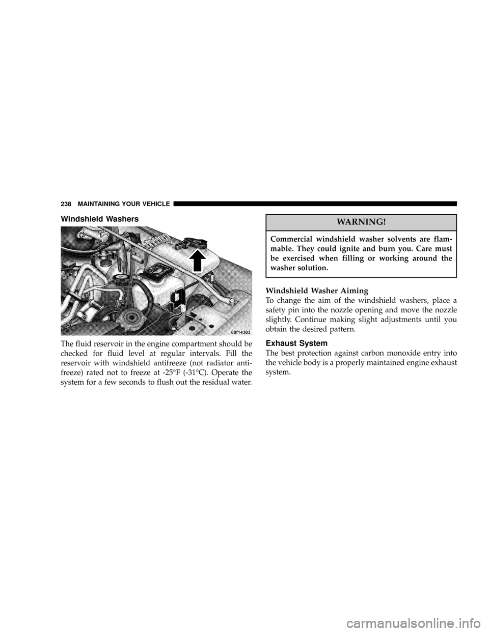
Windshield Washers
The fluid reservoir in the engine compartment should be
checked for fluid level at regular intervals. Fill the
reservoir with windshield antifreeze (not radiator anti-
freeze) rated not to freeze at -25ÉF (-31ÉC). Operate the
system for a few seconds to flush out the residual water.
WARNING!
Commercial windshield washer solvents are flam-
mable. They could ignite and burn you. Care must
be exercised when filling or working around the
washer solution.
Windshield Washer Aiming
To change the aim of the windshield washers, place a
safety pin into the nozzle opening and move the nozzle
slightly. Continue making slight adjustments until you
obtain the desired pattern.
Exhaust System
The best protection against carbon monoxide entry into
the vehicle body is a properly maintained engine exhaust
system.
238 MAINTAINING YOUR VEHICLE
Page 244 of 299

WARNING!
Worn brake hoses can burst and cause brake failure.
You could have an accident. If you see any signs of
cracking, scuffing, or worn spots, have the brake
hoses replaced immediately.
Brake Master Cylinder
The fluid level in the master cylinder should be checked
when performing under hood services, or immediately if
the BRAKE warning light shows system failureBe sure to clean the top of the master cylinder area before
removing the cap. If necessary, add fluid to bring the
fluid level up to the requirements described on the brake
fluid reservoir. With disc brakes, fluid level can be
expected to fall as the brake pads wear. Brake fluid level
should be checked when pads are replaced. However,
low fluid level may be caused by a leak and a checkup
may be needed.
Use only manufacturer's recommended brake fluid, refer
to Recommended Fluids, Lubricants, and Genuine Parts
for correct fluid type.
WARNING!
²Use of a brake fluid that may have a lower initial
boiling point or unidentified as to specification,
may result in sudden brake failure during hard
prolonged braking. You could have an accident.
²Overfilling the brake fluid reservoir can result in
spilling brake fluid on hot engine parts and the
brake fluid catching fire.
244 MAINTAINING YOUR VEHICLE
Page 263 of 299

NOTE:Most vehicles are operated under the conditions
listed for Schedule ªB.º
Second is ScheduleªAº. It is for vehicles that are not
operated under any of the conditions listed under Sched-
ule ªB.º
Use the schedule that best describes your driving condi-
tions. Where time and mileage are listed, follow the
interval that occurs first.
CAUTION!
Failure to perform the required maintenance items
may result in damage to the vehicle.
At Each Stop for Fuel
²
Check the engine oil level about 5 minutes after a fully
warmed engine is shut off. Checking the oil level while
the vehicle is on level ground will improve the accu-
racy of the oil level reading. Add oil only when the
level is at or below the ADD or MIN mark.
²Check the windshield washer solvent, add as required.
Once a Month
²
Check the tire pressure and look for unusual wear or
damage.
²Inspect the battery and clean and tighten the terminals
as required.
²Check the fluid levels of the coolant reservoir, brake
master cylinder, and transmission, and add as needed.
²Check all lights and all other electrical items for correct
operation.
At Each Oil Change
²
Change the engine oil filter.
²Inspect the exhaust system.
²Inspect brake hoses.
²Check the coolant level, hoses, and clamps.
²Inspect manual transmission fluid level Ð if
equipped.
MAINTENANCE SCHEDULES 263
8
M
A
I
N
T
E
N
A
N
C
E
S
C
H
E
D
U
L
E
S
Page 288 of 299

About Your Brakes...................... 177
Add-A-Trunk........................... 65
Adding Washer Fluid.................... 155
Air Cleaner, Engine..................... 234
Air Conditioner Maintenance.............. 235
Air Conditioning....................... 151
Air Conditioning Controls................ 152
Air Conditioning, Operating Tips........... 154
Air Conditioning Refrigerant.............. 236
Air Filter............................. 234
Air Pressure, Tires...................... 192
Airbag................................ 22
Airbag Deployment...................... 27
Airbag Light........................29,118
Airbag Maintenance...................... 29
Airbag On/Off Switch.................... 26
Alignment and Balance.................. 195
Alterations/Modifications, Vehicle............ 8
Antenna, Satellite Radio.................. 147
Antifreeze (Engine Coolant)............... 258
Anti-Lock Brake System.................. 179
Anti-Lock Warning Light................. 119
Appearance Care....................... 248Ashtray............................... 62
Ashtrays and Lighter..................... 62
Automatic Dimming Mirror................ 46
Automatic Transmission...............165,245
Adding Fluid........................ 246
Fluid and Filter Changes................ 245
Fluid Level Check..................... 245
Fluid Type.......................... 245
Gear Ranges......................... 166
Shifting............................ 165
Special Additives..................... 246
Torque Converter..................... 170
Auxiliary Electrical Outlet................. 63
Auxiliary Power Outlet................... 63
Battery............................... 234
Emergency Starting.................... 216
Voltmeter........................... 116
Belts, Drive........................... 231
Belts, Seat............................. 17
Body Mechanism Lubrication.............. 237
Brake System.......................... 243
Anti-Lock........................... 179
288 INDEX
Page 289 of 299

Hoses.............................. 243
Master Cylinder...................... 244
Parking............................ 175
Warning Light....................... 119
Brakes............................... 177
Brake/Transmission Interlock.............. 166
Break-In Recommendations, New Vehicle...... 39
Bulb Replacement...................... 257
Calibration, Compass..................... 47
Capacities, Fluid....................... 258
Caps, Filler
Fuel............................... 200
Power Steering....................... 236
Car Washes........................... 249
Carpeting............................. 252
Cassette Tape and Player Maintenance....... 148
Cassette Tape Player.........126,130,132,140,142
Catalytic Converter..................... 232
Caution, Exhaust Gas..................... 40
CD Changer........................133,138
CD Player......................128,135,137
CD Player Maintenance.................. 149Cellular Phone......................... 149
Chains, Tire........................... 196
Changing A Flat Tire.................... 213
Chart, Tire Sizing....................... 185
Check Engine Light..................... 118
Child Restraint.....................29,33,36
Child Restraint Tether Anchors............. 33
Cigar Lighter........................... 62
Climate Control........................ 149
Clock................................ 120
Clutch Interlocking Ignition System......160,165
Compact Disc Maintenance............... 149
Compact Disc Player.................... 140
Compass.............................. 46
Compass Calibration..................... 47
Compass Variance....................... 48
Console............................... 65
Console, Floor.......................... 65
Contract, Service....................... 282
Converter, Catalytic..................... 232
Cooling System........................ 239
Adding Coolant (Antifreeze)............. 241
Coolant Capacity..................... 258
INDEX 289
10