window JEEP WRANGLER 2013 JK / 3.G Owner's Manual
[x] Cancel search | Manufacturer: JEEP, Model Year: 2013, Model line: WRANGLER, Model: JEEP WRANGLER 2013 JK / 3.GPages: 132, PDF Size: 3.32 MB
Page 35 of 132
CAUTION!
• Do not run a fabric top through an automatic car wash. Window scratches andwax buildup may result.
• Do not lower the top when the temperature is below 41°F (5°C). Damage to the
top may result.
• Do not lower the top when the windows are dirty. Grit may scratch the window.
• Do not move your vehicle until the top has been either fully attached to the
windshield frame, or fully lowered.
• The soft top is not designed to carry any additional loads such as roof racks,
spare tires, building, hunting, or camping supplies, and/or luggage, etc. Also,
it was not designed as a structural member of the vehicle and, thus, cannot
properly carry any additional loads other than environmental (rain, snow, etc.).
WARNING!
•Do not drive the vehicle with the rear window curtain up unless the side curtains
are also open. Dangerous exhaust gases which can kill could enter the vehicle.
• The fabric upper doors and fabric top are designed only for protection againstthe elements. Do not rely on them to contain occupants within the vehicle or to
protect against injury during an accident. Remember, always wear seat belts.
OPERATING YOUR VEHICLE
33
Page 38 of 132
Hard Top Removal
• Follow these simple steps to remove the hard top.
1. Remove both front panels. Refer to “Front Panel(s) Removal” above.
2. Open both doors.
3. Remove the two Torx
®head screws that secure the hard top at the B-pillar (near
the top of the door) using a #40 Torx®head driver (Four–Door Only).
4. Remove the six Torx
®head screws that secure the hard top to the vehicle (along
the interior bodyside) using a #40 Torx®head driver.
5. Open the swing gate all the way to ensure clearance of the rear window glass. Lift the rear window glass.
6.
Locate and disconnect the wire harness on the left rear inside corner of the vehicle.
7. Remove the washer hose (next to the wire harness) by pinching the grips on
hose connector and pull downward.
8. Close the swing gate.
9. Remove the hard top from the vehicle. Place the hard top on a soft surface to
prevent damage.
CAUTION!
• The front panel(s) must be positioned properly to ensure sealing. Improperinstallation can cause water to leak into the vehicles interior.
• The hard top assembly must be positioned properly to ensure sealing. Improper
installation can cause water to leak into the vehicles interior.
• The hard top is not designed to carry any additional loads such as roof racks,
spare tires, building, hunting, or camping supplies, and/or luggage, etc. Also,
it was not designed as a structural member of the vehicle, and thus cannot
properly carry any additional loads other than environmental (rain, snow, etc.).
• Do not move your vehicle until the top has been either fully attached to the
windshield frame and bodyside, or fully removed.
• The removal of the hard top requires four adults located on each corner. Failure
to follow this caution could damage the hard top.
OPERATING YOUR VEHICLE
36
Page 39 of 132
DUAL TOP — IF EQUIPPED
• If your vehicle is equipped with a Dual Top, you must remove one of the tops fromthe vehicle.
• 2 Door - If the soft top is removed, the pivot brackets must also be removed from
the sport bar.
• 4 Door - If the soft top is removed, ensure that the pivot bracket strap is installed onto
the Soft Top pivot bracket before removing the soft top from the vehicle. Remove the
fasteners between the Soft Top pivot bracket and the attach bracket to the sport
bar.
• The soft top was installed at the fac- tory for shipping purposes only.
NOTE:
The soft top and the hard top are to be
used independently.
• Refer to the Understanding The Fea- tures Of Your Vehicle section of your
vehicle's Owner's Manual on the DVD
for further details.
WIND BUFFETING
•Wind buffeting can be described as a helicopter-type percussion sound. If buffeting
occurs with the rear windows open, adjust the front and rear windows together.
OPERATING YOUR VEHICLE
37
Page 118 of 132
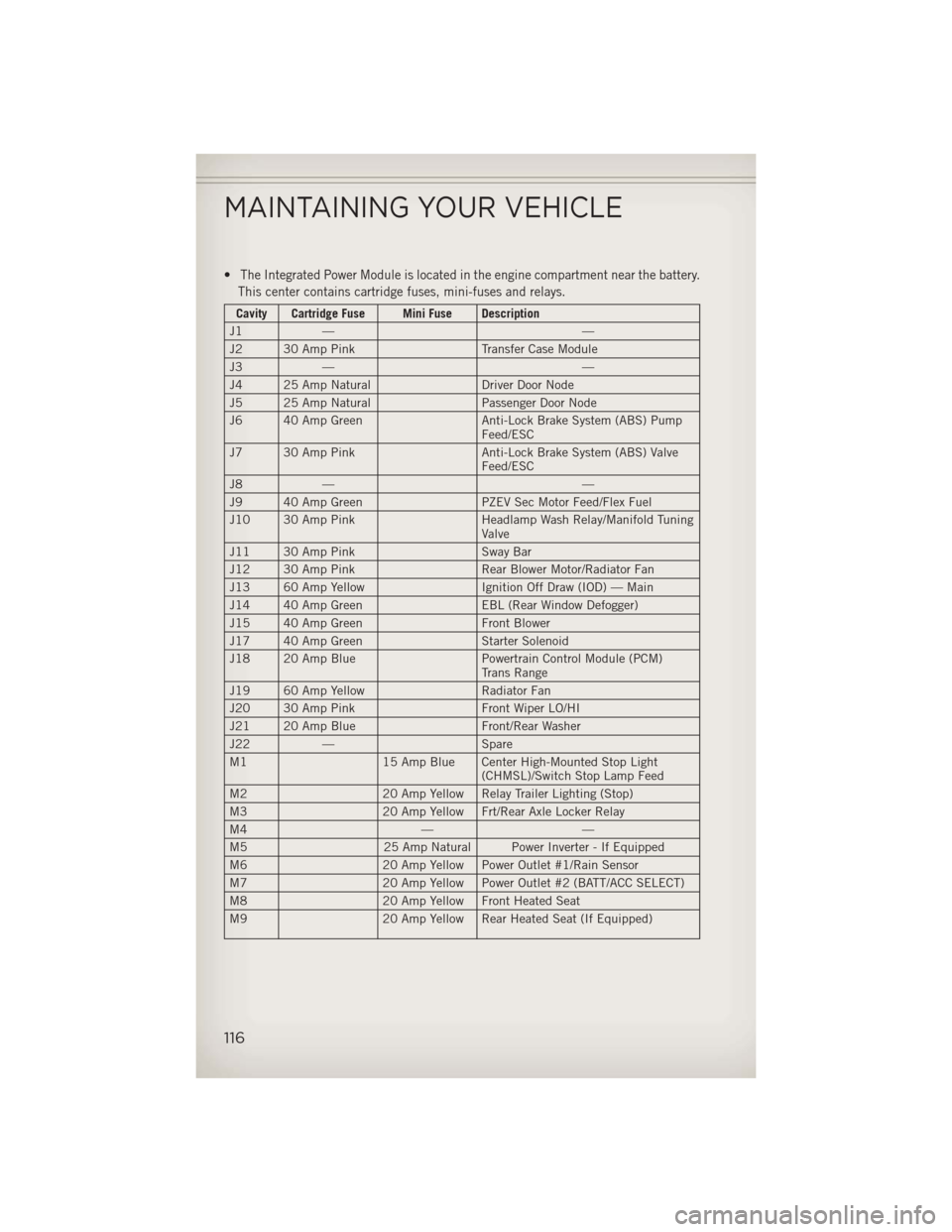
•The Integrated Power Module is located in the engine compartment near the battery.
This center contains cartridge fuses, mini-fuses and relays.
Cavity Cartridge Fuse Mini Fuse Description
J1 — —
J2 30 Amp Pink Transfer Case Module
J3 — —
J4 25 Amp Natural Driver Door Node
J5 25 Amp Natural Passenger Door Node
J6 40 Amp Green Anti-Lock Brake System (ABS) Pump
Feed/ESC
J7 30 Amp Pink Anti-Lock Brake System (ABS) Valve
Feed/ESC
J8 — —
J9 40 Amp Green PZEV Sec Motor Feed/Flex Fuel
J10 30 Amp Pink Headlamp Wash Relay/Manifold Tuning
Valve
J11 30 Amp Pink Sway Bar
J12 30 Amp Pink Rear Blower Motor/Radiator Fan
J13 60 Amp Yellow Ignition Off Draw (IOD) — Main
J14 40 Amp Green EBL (Rear Window Defogger)
J15 40 Amp Green Front Blower
J17 40 Amp Green Starter Solenoid
J18 20 Amp Blue Powertrain Control Module (PCM)
Trans Range
J19 60 Amp Yellow Radiator Fan
J20 30 Amp Pink Front Wiper LO/HI
J21 20 Amp Blue Front/Rear Washer
J22 — Spare
M1 15 Amp Blue Center High-Mounted Stop Light
(CHMSL)/Switch Stop Lamp Feed
M2 20 Amp Yellow Relay Trailer Lighting (Stop)
M3 20 Amp Yellow Frt/Rear Axle Locker Relay
M4 ——
M5 25 Amp Natural Power Inverter - If Equipped
M6 20 Amp Yellow Power Outlet #1/Rain Sensor
M7 20 Amp Yellow Power Outlet #2 (BATT/ACC SELECT)
M8 20 Amp Yellow Front Heated Seat
M9 20 Amp Yellow Rear Heated Seat (If Equipped)
MAINTAINING YOUR VEHICLE
116
Page 120 of 132
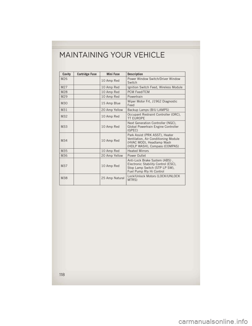
Cavity Cartridge Fuse Mini Fuse Description
M26 10 Amp RedPower Window Switch/Driver Window
Switch
M27 10 Amp Red Ignition Switch Feed, Wireless Module
M28 10 Amp Red PCM Feed/TCM
M29 10 Amp Red Powertrain
M30 15 Amp Blue Wiper Motor Frt, J1962 Diagnostic
Feed
M31 20 Amp Yellow Backup Lamps (B/U LAMPS)
M32 10 Amp Red Occupant Restraint Controller (ORC),
TT EUROPE
M33 10 Amp Red Next Generation Controller (NGC),
Global Powertrain Engine Controller
(GPEC)
M34 10 Amp Red Park Assist (PRK ASST), Heater
Ventilation, Air Conditioning Module
(HVAC MOD), Headlamp Wash
(HDLP WASH), Compass (COMPAS)
M35 10 Amp Red Heated Mirrors
M36 20 Amp Yellow Power Outlet
M37 10 Amp Red Anti-Lock Brake System (ABS) ,
Electronic Stability Control (ESC),
Stop Lamp Switch (STP LP SW),
Fuel Pump Rly Hi Control
M38 25 Amp Natural Lock/Unlock Motors (LOCK/UNLOCK
MTRS)
MAINTAINING YOUR VEHICLE
118