air condition JEEP WRANGLER 2013 JK / 3.G User Guide
[x] Cancel search | Manufacturer: JEEP, Model Year: 2013, Model line: WRANGLER, Model: JEEP WRANGLER 2013 JK / 3.GPages: 132, PDF Size: 3.32 MB
Page 21 of 132
HEATED SEATS
Front Heated Seats
• The controls for front heated seats arelocated near the bottom center of the
instrument panel (below the heater/air
conditioning controls).
•
Press the switch once to select High-
level heating. Press the switch a second
time to select Low-level heating. Press
the switch a third time to shut the
heating elements Off.
•If the High-level setting is selected, the
system will automatically switch to Low-
level after approximately 30 minutes.
The Low-level setting will turn Off automatically after approximately 30 minutes.
WARNING!
• Persons who are unable to feel pain to the skin because of advanced age,
chronic illness, diabetes, spinal cord injury, medication, alcohol use, exhaus-
tion or other physical conditions must exercise care when using the seat heater.
It may cause burns even at low temperatures, especially if used for long periods
of time.
• Do not place anything on the seat that insulates against heat, such as a blanket
or cushion. This may cause the seat heater to overheat. Sitting in a seat that
has been overheated could cause serious burns due to the increased surface
temperature of the seat.
GETTING STARTED
19
Page 27 of 132
AUTOMATIC TEMPERATURE CONTROLS (ATC)
Automatic Operation
• Turn the Mode and Blower Controls to the AUTO position.
• Select the desired temperature by rotating the Temperature Control.
• The system will maintain the set temperature automatically.
Air Conditioning (A/C)
• If the air conditioning button is pressed while in AUTO mode, the LED in thecontrol button will flash three times and then turn off. This indicates that the
system is in AUTO mode and requesting the air conditioning is not necessary.
Air Recirculation
• Use Recirculation for maximum A/C operation.
• For window defogging, turn the recirculation button off.
• If the recirculation button is pressed while in the AUTO mode, the indicator lightmay flash three times to indicate the cabin air is being controlled automatically.
Heated Mirrors
• The mirrors are heated to melt frost or ice. This feature is activated whenever youturn on the defroster.
OPERATING YOUR VEHICLE
25
Page 78 of 132
Mute (Or Unmute) Microphone During Call
• During a call, press the “Voice Command” button.
• After the BEEP, say “mute” (or “mute off”).
Transfer Ongoing Call Between Handset And Vehicle
• During a call, press the “Voice Command” button.
• After the BEEP, say “transfer call”.
Changing The Volume
•Start a dialogue by pressing the “Phone” button, then adjust the volume during
a normal call.
• Use the radio ON/OFF VOLUME rotary knob to adjust the volume to a comfortable level while the Uconnect®system is speaking. Please note the volume setting for
Uconnect®is different than the audio system.
WARNING!
•Any voice commanded system should be used only in safe driving conditions
following applicable laws regarding phone use. Your attention should be focused
on safely operating the vehicle. Failure to do so may result in a collision causing
you and others to be severely injured or killed.
• In an emergency, to use Uconnect®Phone, your mobile phone must be:
• turned on,
• paired to Uconnect
®Phone,
• and have network coverage.
Uconnect® VOICE COMMAND
Voice Command Operation
•The Uconnect®Voice Command system allows you to control your AM, FM radio,
satellite radio, disc player, HDD, Uconnect®Phone, a memo recorder, and supported
portable media devices.
•When you press the “Voice Command” buttonlocated on the radio faceplate
or steering wheel, you will hear a beep. The beep is your signal to give a command.
If you do not say a command within a few seconds, the system will present you with
a list of options. If you ever wish to interrupt the system while it lists options, press
the “Voice Command” button
, listen for the BEEP, and say your command.
ELECTRONICS
76
Page 80 of 132
While In:Voice Command Example:
Memo Mode To switch to the voice recorder mode, say “Memo”.
The following are common voice commands for this mode: “New Memo” (to record a new memo) — During the recording, you
may press the Voice Command button
to stop recording.
You proceed by saying one of the following commands:
— “Save” (to save the memo)
— “Continue” (to continue recording) — “Delete” (to delete the recording)
— “Play Memos” (to play previously recorded memos)
— During the playback you may press the Voice Command button
to stop playing memos. You proceed by
saying one of the following commands:
— “Repeat” (to repeat a memo)
— “Next” (to play the next memo)
— “Previous” (to play the previous memo) — “Delete” (to delete a memo)
— “Delete All” (to delete all memos)
Voice Text Reply
•If equipped with Uconnect®Voice Command, your Uconnect®430N, 730N & 731N
radios may be able to play incoming Short Message Service (SMS) messages (text
messages) through the vehicle's sound system.
• It also allows you to respond by selecting from various pre - defined phrases.
• Not all phones are compatible with this feature. Refer to the phone compatibility list at www.UconnectPhone.com. Connected mobile phones must be bluetooth-
compatible and paired with your radio.
•
Press the “Voice Command” buttonand after the BEEP, say “SMS” to get
started.
NOTE:
To access the tutorial, press the “Voice Command” button
. After the BEEP,
say “tutorial”. Press any hard-key/button or touch the display (Touch-Screen radio) to
cancel the tutorial.
WARNING!
Any voice commanded system should be used only in safe driving conditions
following applicable laws regarding phone use. Your attention should be focused
on safely operating the vehicle. Failure to do so may result in a collision causing
you and others to be severely injured or killed.
ELECTRONICS
78
Page 94 of 132
•IF THE LIGHT STARTS FLASHING INDICATING A LOW TIRE PRESSURE, ADJUST THE AIR
PRESSURE IN THE LOW TIRE TO THE AIR PRESSURE SHOWN ON THE VEHICLE PLACARD
OR TIRE INFLATION PRESSURE LABEL LOCATED ON THE DRIVER'S DOOR.
NOTE:
AFTER INFLATION, THE VEHICLE MAY NEED TO BE DRIVEN FOR 20 MINUTES
BEFORE THE FLASHING LIGHT WILL TURN OFF.
•
Please note that the TPMS is not a substitute for proper tire maintenance, and it is
the driver’s responsibility to maintain correct tire pressure, even if under-inflation has
not reached the level to trigger illumination of the TPMS low tire pressure telltale.
•Your vehicle has also been equipped with a TPMS malfunction indicator to indicate
when the system is not operating properly. The TPMS malfunction indicator is
combined with the low tire pressure telltale. When the system detects a malfunction,
the telltale will flash for approximately one minute and then remain continuously
illuminated. This sequence will continue each time the vehicle is restarted as long as
the malfunction exists.
• When the malfunction indicator is illuminated, the system may not be able to detect or signal low tire pressure as intended. TPMS malfunctions may occur for a
variety of reasons, including the installation of replacement or alternate tires or
wheels on the vehicle that prevent the TPMS from functioning properly. Always
check the TPMS malfunction telltale after replacing one or more tires or wheels on
your vehicle, to ensure that the replacement or alternate tires and wheels allow the
TPMS to continue to function properly.
NOTE:
Tire pressures change by approximately 1 psi (7 kPa) per 12° F (7° C) of air temperature
change. Keep this in mind when checking tire pressure inside a garage, especially in the
Winter. Example: If garage temperature is 68°F (20°C) and the outside temperature is
32°F (0°C), then the cold tire inflation pressure should be increased by 3 psi (21 kPa),
which equals 1 psi (7 kPa) for every 12°F (7°C) for this outside temperature condition.
CAUTION!
The TPMS has been optimized for the original equipment tires and wheels. TPMS
pressures and warning have been established for the tire size equipped on your
vehicle. Undesirable system operation or sensor damage may result when using
replacement equipment that is not of the same size, type, and/or style. After-
market wheels can cause sensor damage. Do not use tire sealant from a can, or
balance beads if your vehicle is equipped with a TPMS, as damage to the sensors
may result.
WHAT TO DO IN EMERGENCIES
92
Page 98 of 132
IF YOUR ENGINE OVERHEATS
• In any of the following situations, you can reduce the potential for overheating bytaking the appropriate action.
• On the highways — slow down.
• In city traffic — while stopped, place the transmission in NEUTRAL, but do not increase engine idle speed.
NOTE:
There are steps that you can take to slow down an impending overheat condition:
• If your air conditioner (A/C) is on, turn it off. The A/C system adds heat to the engine cooling system and turning the A/C off can help remove this heat.
•
You can also turn the temperature control to maximum heat, the mode control to floor
and the blower control to high. This allows the heater core to act as a supplement to
the radiator and aids in removing heat from the engine cooling system.
CAUTION!
Driving with a hot cooling system could damage your vehicle. If the temperature
gauge reads HOT (H), pull over and stop the vehicle. Idle the vehicle with the air
conditioner turned off until the pointer drops back into the normal range. If the
pointer remains on HOT (H), and you hear continuous chimes, turn the engine off
immediately, and call for service.
WARNING!
You or others can be badly burned by hot engine coolant (antifreeze) or steam from
your radiator. If you see or hear steam coming from under the hood, do not open
the hood until the radiator has had time to cool. Never try to open a cooling system
pressure cap when the radiator or coolant bottle is hot.
WHAT TO DO IN EMERGENCIES
96
Page 107 of 132
EVENT DATA RECORDER (EDR)
• This vehicle is equipped with an Event Data Recorder (EDR). The main purpose ofan EDR is to record, in certain crash or near crash-like situations, such as an air
bag deployment or hitting a road obstacle, data that will assist in understanding
how a vehicle’s systems performed. The EDR is designed to record data related to
vehicle dynamics and safety systems for a short period of time, typically 30 sec-
onds or less. The EDR in this vehicle is designed to record such data as:• How various systems in your vehicle were operating.
• Whether or not the driver and passenger safety belts were buckled/fastened.
• How far (if at all) the driver was depressing the accelerator and/or brake pedal.
• How fast the vehicle was traveling.
• These data can help provide a better understanding of the circumstances in which crashes and injuries occur.
NOTE:
EDR data are recorded by your vehicle only if a non-trivial crash situation occurs; no
data are recorded by the EDR under normal driving conditions and no personal data
(e.g. name, gender, age, and crash location) are recorded. However, other parties,
such as law enforcement, could combine the EDR data with the type of personally
identifying data routinely acquired during a crash investigation.
• To read data recorded by an EDR, special equipment is required, and access to the vehicle or the EDR is needed. In addition to the vehicle manufacturer, other parties
such as law enforcement, that have the special equipment, can read the informa-
tion if they have access to the vehicle or the EDR.
WHAT TO DO IN EMERGENCIES
105
Page 113 of 132
Once A Month Or Before A Long Trip:
• Check engine oil level
• Check windshield washer fluid level
• Check the tire inflation pressures and look for unusual wear or damage
• Check the fluid levels of the coolant reservoir, brake master cylinder, powersteering and transmission as needed
• Check function of all interior and exterior lights
Required Maintenance Intervals.
Refer to the maintenance schedules on the following page for the required mainte-
nance intervals.
At Every Oil Change Interval As Indicated By Oil Change Indicator System:
• Change oil and filter
• Rotate the tires. Rotate at the first sign of irregular wear, even if it occurs before the oil
indicator system turns on.
• Inspect battery and clean and tighten terminals as required
• Inspect automatic transmission fluid if equipped with dipstick
• Inspect brake pads, shoes, rotors, drums, hoses and park brake
• Inspect engine cooling system protection and hoses
• Inspect exhaust system
• Inspect engine air cleaner if using in dusty or off-road conditions
• Inspect all door latches for presence of grease, reapply if necessary.
MAINTAINING YOUR VEHICLE
111
Page 119 of 132
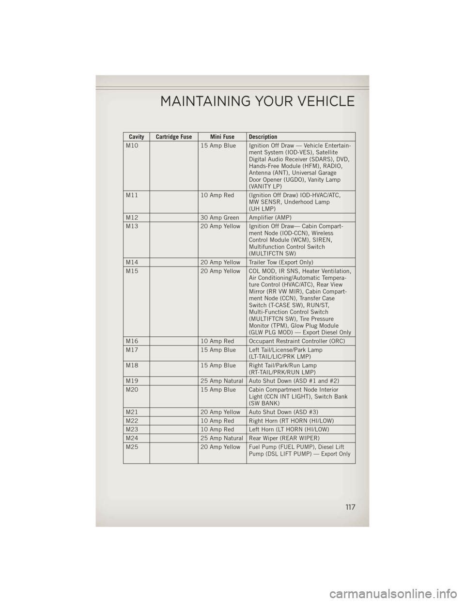
Cavity Cartridge Fuse Mini Fuse Description
M10 15 Amp Blue Ignition Off Draw — Vehicle Entertain-
ment System (IOD-VES), Satellite
Digital Audio Receiver (SDARS), DVD,
Hands-Free Module (HFM), RADIO,
Antenna (ANT), Universal Garage
Door Opener (UGDO), Vanity Lamp
(VANITY LP)
M11 10 Amp Red (Ignition Off Draw) IOD-HVAC/ATC,
MW SENSR, Underhood Lamp
(UH LMP)
M12 30 Amp Green Amplifier (AMP)
M13 20 Amp Yellow Ignition Off Draw— Cabin Compart-
ment Node (IOD-CCN), Wireless
Control Module (WCM), SIREN,
Multifunction Control Switch
(MULTIFCTN SW)
M14 20 Amp Yellow Trailer Tow (Export Only)
M15 20 Amp Yellow COL MOD, IR SNS, Heater Ventilation,
Air Conditioning/Automatic Tempera-
ture Control (HVAC/ATC), Rear View
Mirror (RR VW MIR), Cabin Compart-
ment Node (CCN), Transfer Case
Switch (T-CASE SW), RUN/ST,
Multi-Function Control Switch
(MULTIFTCN SW), Tire Pressure
Monitor (TPM), Glow Plug Module
(GLW PLG MOD) — Export Diesel Only
M16 10 Amp Red Occupant Restraint Controller (ORC)
M17 15 Amp Blue Left Tail/License/Park Lamp
(LT-TAIL/LIC/PRK LMP)
M18 15 Amp Blue Right Tail/Park/Run Lamp
(RT-TAIL/PRK/RUN LMP)
M19 25 Amp Natural Auto Shut Down (ASD #1 and #2)
M20 15 Amp Blue Cabin Compartment Node Interior
Light (CCN INT LIGHT), Switch Bank
(SW BANK)
M21 20 Amp Yellow Auto Shut Down (ASD #3)
M22 10 Amp Red Right Horn (RT HORN (HI/LOW)
M23 10 Amp Red Left Horn (LT HORN (HI/LOW)
M24 25 Amp Natural Rear Wiper (REAR WIPER)
M25 20 Amp Yellow
Fuel Pump (FUEL PUMP), Diesel Lift
Pump (DSL LIFT PUMP) — Export Only
MAINTAINING YOUR VEHICLE
117
Page 120 of 132
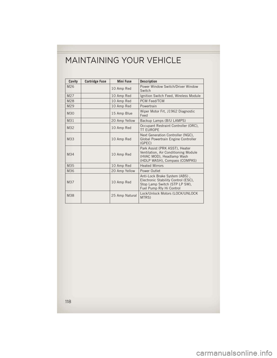
Cavity Cartridge Fuse Mini Fuse Description
M26 10 Amp RedPower Window Switch/Driver Window
Switch
M27 10 Amp Red Ignition Switch Feed, Wireless Module
M28 10 Amp Red PCM Feed/TCM
M29 10 Amp Red Powertrain
M30 15 Amp Blue Wiper Motor Frt, J1962 Diagnostic
Feed
M31 20 Amp Yellow Backup Lamps (B/U LAMPS)
M32 10 Amp Red Occupant Restraint Controller (ORC),
TT EUROPE
M33 10 Amp Red Next Generation Controller (NGC),
Global Powertrain Engine Controller
(GPEC)
M34 10 Amp Red Park Assist (PRK ASST), Heater
Ventilation, Air Conditioning Module
(HVAC MOD), Headlamp Wash
(HDLP WASH), Compass (COMPAS)
M35 10 Amp Red Heated Mirrors
M36 20 Amp Yellow Power Outlet
M37 10 Amp Red Anti-Lock Brake System (ABS) ,
Electronic Stability Control (ESC),
Stop Lamp Switch (STP LP SW),
Fuel Pump Rly Hi Control
M38 25 Amp Natural Lock/Unlock Motors (LOCK/UNLOCK
MTRS)
MAINTAINING YOUR VEHICLE
118