wheel JEEP WRANGLER 2013 JK / 3.G User Guide
[x] Cancel search | Manufacturer: JEEP, Model Year: 2013, Model line: WRANGLER, Model: JEEP WRANGLER 2013 JK / 3.GPages: 132, PDF Size: 3.32 MB
Page 3 of 132
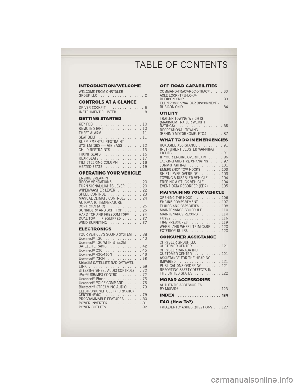
INTRODUCTION/WELCOME
WELCOME FROM CHRYSLER
GROUP LLC.................. 2
CONTROLS AT A GLANCE
DRIVER COCKPIT .............. 6
INSTRUMENT CLUSTER .......... 8
GETTING STARTED
KEYFOB ................... 10
REMOTE START.............. 10
THEFT ALARM ................ 11
SEATBELT .................. 11
SUPPLEMENTAL RESTRAINT
SYSTEM (SRS) — AIR BAGS ....... 12
CHILD RESTRAINTS ............ 13
FRONT SEATS ................ 15
REAR SEATS ................. 17
TILT STEERING COLUMN ......... 18
HEATEDSEATS ............... 19
OPERATING YOUR VEHICLE
ENGINE BREAK-IN
RECOMMENDATIONS ........... 20
TURN SIGNAL/LIGHTS LEVER ...... 20
WIPER/WASHER LEVER .......... 22
SPEED CONTROL .............. 23
MANUAL CLIMATE CONTROLS ...... 24
AUTOMATIC TEMPERATURE
CONTROLS (ATC) .............. 25
SUNRIDER
®AND SOFT TOP ....... 26
HARD TOP AND FREEDOM TOP®.... 34
DUAL TOP — IF EQUIPPED ........ 37
WIND BUFFETING ............. 37
ELECTRONICS
YOUR VEHICLE'S SOUND SYSTEM . . . 38
Uconnect®130 ............... 40
Uconnect®130 WITH SiriusXM
SATELLITE RADIO .............. 42
Uconnect
®230 ............... 45
Uconnect®430/430N ........... 48
Uconnect®730N .............. 58
SiriusXM SATELLITE RADIO/TRAVEL
LINK ...................... 69
STEERING WHEEL AUDIO CONTROLS.. 72
iPod®/USB/MP3 CONTROL ........ 72
Uconnect®Phone .............. 73
Uconnect®VOICE COMMAND ....... 76
Bluetooth®STREAMING AUDIO ..... 79ELECTRONIC VEHICLE INFORMATION
CENTER (EVIC)............... 79
PROGRAMMABLE FEATURES ....... 80
POWER INVERTER ............. 81
POWER OUTLETS ............. 82
OFF-ROAD CAPABILITIES
COMMAND-TRAC®/ROCK-TRAC®..... 83
AXLE LOCK (TRU-LOK®)
RUBICON ONLY ............... 83
ELECTRONIC SWAY BAR DISCONNECT –
RUBICON ONLY............... 84
UTILITY
TRAILER TOWING WEIGHTS
(MAXIMUM TRAILER WEIGHT
RATINGS).................. 85
RECREATIONAL TOWING
(BEHIND MOTORHOME, ETC.) ..... 87
WHAT TO DO IN EMERGENCIES
ROADSIDE ASSISTANCE.......... 91
INSTRUMENT CLUSTER WARNING
LIGHTS .................... 91
IF YOUR ENGINE OVERHEATS ...... 96
JACKING AND TIRE CHANGING ..... 97
JUMP-STARTING ............. 101
EMERGENCY TOW HOOKS ....... 103
SHIFT LEVER OVERRIDE ........ 103
TOWING A DISABLED VEHICLE .... 104
FREEING A STUCK VEHICLE ...... 104
EVENT DATA RECORDER (EDR) .... 105
MAINTAINING YOUR VEHICLE
OPENING THE HOOD.......... 106
ENGINE COMPARTMENT ........ 107
FLUIDS AND CAPACITIES ........ 108
MAINTENANCE SCHEDULE ...... 110
MAINTENANCE RECORD ........ 114
FUSES .................... 115
TIRE PRESSURES ............ 119
WHEEL AND WHEEL TRIM CARE . . . 120
EXTERIOR BULBS ............ 120
CONSUMER ASSISTANCE
CHRYSLER GROUP LLC
CUSTOMER CENTER ........... 121
CHRYSLER CANADA INC.
CUSTOMER CENTER ........... 121
ASSISTANCE FOR THE HEARING
IMPAIRED ................. 121
PUBLICATIONS ORDERING ....... 121
REPORTING SAFETY DEFECTS IN
THEUNITEDSTATES ........... 122
MOPAR ACCESSORIES
AUTHENTIC ACCESSORIES
BY MOPAR®................ 123
INDEX.................. 124
FAQ(HowTo?)
FREQUENTLY ASKED QUESTIONS . . . 127
TABLE OF CONTENTS
Page 5 of 132
Chrysler Group LLC is committed to protecting our environment and natural resources.
By converting from paper to electronic delivery for the majority of the user information
for your vehicle, together we greatly reduce the demand for tree-based products and
lessen the stress on our environment.
This is a specialized utility vehicle designed for both on-road and off-road use. It can go
places and perform tasks for which conventional two-wheel drive enclosed vehicles were
not intended. It handles and maneuvers differently from many passenger cars both
on-road and off-road, so take time to become familiar with your vehicle.
VEHICLES SOLD IN CANADA
With respect to any vehicles sold in Canada, the name Chrysler Group LLC shall be
deemed to be deleted and the name Chrysler Canada Inc. used in substitution.
WARNING!
• Pedals that cannot move freely can cause loss of vehicle control and increasethe risk of serious personal injury.
• Always make sure that objects cannot fall into the driver foot well while the
vehicle is moving. Objects can become trapped under the brake pedal and
accelerator pedal causing a loss of vehicle control.
• Failure to properly follow floor mat installation or mounting can cause inter-
ference with the brake pedal and accelerator pedal operation causing loss of
control of the vehicle.
• Never use the ‘PARK’ position as a substitute for the parking brake. Always
apply the parking brake fully when parked to guard against vehicle movement
and possible injury or damage.
• Refer to your Owner's Manual on the DVD for further details.
INTRODUCTION/WELCOME
3
Page 9 of 132
A. Electronic Vehicle Information Center(EVIC) Controls pg. 79
B. Turn Signal/Lights Lever (behind steering wheel) pg. 20
C. Electronic Vehicle Information Center (EVIC) Display (behind steering
wheel) pg. 8
D. Instrument Cluster pg. 8
E. Wiper/Washer Lever (behind steering wheel) pg. 22
F. Power Windows G. Audio System (touch-screen-radio
shown) pg. 38
H. Climate Controls pg. 24
I. Power Outlet/Cigar Lighter pg. 82
J. SWITCH PANEL • Heated Seat Switches pg. 19
• Electronic Stability Control pg. 91
• Hill Descent
• Hazard Switch
K. Transmission Gear Selector L. Transfer Case Gear Selector
M. Power Mirrors
N. Electronic Speed Control pg. 23
O. Ignition Switch
P. Tilt Steering Column Lever pg. 18
Q. Power Door Locks
CONTROLS AT A GLANCE
7
Page 14 of 132
WARNING!
In a collision, you and your passengers can suffer much greater injuries if you are
not buckled up properly. You can strike the interior of your vehicle or other
passengers, or you can be thrown out of the vehicle. Always be sure you and others
in your vehicle are buckled up properly.
SUPPLEMENTAL RESTRAINT SYSTEM (SRS) —
AIR BAGS
• This vehicle has Advanced Front Air Bags for both the driver and right frontpassenger as a supplement to the seat belt restraint system. The Advanced Front
Air Bags will not deploy in every type of collision.
• Advanced Front Air Bags are designed to provide additional protection by supplementing the seat belts in certain frontal collisions depending on several
factors, including the severity and type of collision. Advanced Front Air Bags are
not expected to reduce the risk of injury in rear, side, or rollover collisions.
• This vehicle may be equipped with Supplemental Seat-Mounted Side Air Bags to provide enhanced protection to help protect an occupant during a side impact.
•
If the Air Bag Warning Lightis not on during starting, stays on, or turns on while
driving, have the vehicle serviced by an authorized service center immediately.
•Refer to the Owner's Manual on the DVD for further details regarding the Supple-
mental Restraint System (SRS).
WARNING!
• Relying on the air bags alone could lead to more severe injuries in a collision. The air bags work with your seat belt to restrain you properly. In some
collisions, the air bags won't deploy at all. Always wear your seat belts even
though you have air bags.
• Being too close to the steering wheel or instrument panel during Advanced
Front Air Bag deployment could cause serious injury, including death. Air bags
need room to inflate. Sit back, comfortably extending your arms to reach the
steering wheel or instrument panel.
• Supplemental Seat-Mounted Side Air Bags need room to inflate. Do not lean
against the door or window. Sit upright in the center of the seat.
• Being too close to the Seat-Mounted Side Air Bag during deployment could
cause you to be severely injured or killed.
• Do not drive your vehicle after the air bags have deployed. If you are involved
in another collision, the air bags will not be in place to protect you.
• After any collision, the vehicle should be taken to an authorized dealer
immediately.
GETTING STARTED
12
Page 20 of 132
TILT STEERING COLUMN
• The tilt lever is located on the steeringcolumn, below the turn signal lever.
• Push down on the lever to unlock the steering column.
• With one hand firmly on the steering wheel, move the steering column up or
down as desired.
• Pull upward on the lever to lock the column firmly in place.
WARNING!
Do not adjust the steering column while driving. Adjusting the steering column
while driving, or driving with the steering column unlocked, could cause the driver
to lose control of the vehicle. Be sure the steering column is locked before driving
your vehicle. Failure to follow this warning may result in you or others being
severely injured or killed.
GETTING STARTED
18
Page 25 of 132
SPEED CONTROL
• The Electronic Speed Control switchesare located on the steering wheel.
Cruise ON/OFF
• Push the ON/OFF switch to activatethe Speed Control.
• The cruise symbol
will appear on
the instrument cluster to indicate the
Speed Control is on.
•
Push the ON/OFF switch a second time
to turn the system off.
Set
• With the Speed Control on, push and release the SET – button to set a de-
sired speed.
Accel/Decel
• Once a speed is set, pushing the RES + button once or the SET – button once willincrease or decrease the set speed approximately 1 mph (1.6 km/h).
• Push and hold the RES + button to accelerate in 5 mph (8 km/h) increments or push and hold the SET – button to decelerate in 5 mph (8 km/h) increments;
release the button to save the new set speed.
Resume
• To resume a previously selected set speed in memory, push the RES + button andrelease.
Cancel
• Push the CANCEL switch, or apply the brakes or clutch, to cancel the set speedand maintain the set speed memory.
• Push the ON/OFF switch to turn the system off and erase the set speed memory.
OPERATING YOUR VEHICLE
23
Page 74 of 132
STEERING WHEEL AUDIO CONTROLS
• The steering wheel audio controls arelocated on the rear surface of the steer-
ing wheel.
Right Switch
•Press the switch up or down to increase
or decrease the volume.
•Press the button in the center to change
modes AM/FM/CD/SAT.
Left Switch
• Press the switch up or down to search for the next listenable station or select
the next or previous CD track.
• Press the button in the center to select the next preset station (radio) or to change CDs if equipped with a CD Changer.
iPod®/USB/MP3 CONTROL
•There are many ways to play music from iPod®/MP3 players or USB devices through
your vehicle's sound system.
•The remote USB port, located within the center console, allows you to plug an iPod®
into the vehicle's sound system.
NOTE:
If equipped with the Uconnect®730N or 731N the USB port on the faceplate allows
the same functions as the remote USB port.
• Non-Touch-Screen Radios: To hear audio from devices connected to the USB port,
press the “AUX” button on the radio face plate
• Touch-Screen Radios: To hear audio from devices connected to the USB port, press
the “MEDIA” hard-key, then touch the “AUX” or “iPod
®” soft-key.
• When connected to this feature: •
The iPod®can be controlled using
the radio buttons to Play, Browse,
and List the iPod
®or external devices
contents.
•The iPod®battery charges when
plugged into the USB port (if sup-
ported by the specific audio device).
• Compatible iPod®devices may also
be controllable using voice commands. Refer to the Owner's Manual on the DVD
for details.
ELECTRONICS
72
Page 78 of 132
Mute (Or Unmute) Microphone During Call
• During a call, press the “Voice Command” button.
• After the BEEP, say “mute” (or “mute off”).
Transfer Ongoing Call Between Handset And Vehicle
• During a call, press the “Voice Command” button.
• After the BEEP, say “transfer call”.
Changing The Volume
•Start a dialogue by pressing the “Phone” button, then adjust the volume during
a normal call.
• Use the radio ON/OFF VOLUME rotary knob to adjust the volume to a comfortable level while the Uconnect®system is speaking. Please note the volume setting for
Uconnect®is different than the audio system.
WARNING!
•Any voice commanded system should be used only in safe driving conditions
following applicable laws regarding phone use. Your attention should be focused
on safely operating the vehicle. Failure to do so may result in a collision causing
you and others to be severely injured or killed.
• In an emergency, to use Uconnect®Phone, your mobile phone must be:
• turned on,
• paired to Uconnect
®Phone,
• and have network coverage.
Uconnect® VOICE COMMAND
Voice Command Operation
•The Uconnect®Voice Command system allows you to control your AM, FM radio,
satellite radio, disc player, HDD, Uconnect®Phone, a memo recorder, and supported
portable media devices.
•When you press the “Voice Command” buttonlocated on the radio faceplate
or steering wheel, you will hear a beep. The beep is your signal to give a command.
If you do not say a command within a few seconds, the system will present you with
a list of options. If you ever wish to interrupt the system while it lists options, press
the “Voice Command” button
, listen for the BEEP, and say your command.
ELECTRONICS
76
Page 81 of 132
Bluetooth® STREAMING AUDIO
• If equipped with Uconnect®Voice
Command, your Bluetooth-equipped
iPod
®devices, cell phones or other
media players, may also be able to
stream music to your vehicles speak-
ers. Your connected device must be
Bluetooth-compatible, and paired with
your radio (see Uconnect
®Phone for
pairing instructions).
• Non-Touch-Screen Radios: Press the
“AUX” button on the radio faceplate until "BT" or “Audio Streaming” is displayed
on the radio screen.
• Touch-Screen-Radios: Press the “RADIO/MEDIA” or “MEDIA” hard-key and then
touch the “AUX” soft-key tab.
ELECTRONIC VEHICLE INFORMATION CENTER (EVIC)
• The EVIC features a driver interactive display that is located in the instru-
ment cluster. Pressing the controls on
the steering wheel allows the driver to
select vehicle information and Per-
sonal Settings. For additional informa-
tion, refer to Programmable Features
in this guide.
• Press and release the MENU button to scroll through the main menus (Fuel
Economy, Warnings, Timer, Units, Sys-
tem, Personal Settings) or to exit sub
menus.
• Press and release the SELECT
button for access to main menus, sub menus or
to select a personal setting in the setup menu.
• Press and release the COMPASS
button to display one of eight compass
readings and the outside temperature or to exit sub menus.
•
Press and release the DOWNbutton to scroll downward through the sub menus.
Compass Calibration
• This compass is self-calibrating, which eliminates the need to set the compass manually. When the vehicle is new, the compass may appear erratic and the EVIC
will display “CAL” until the compass is calibrated.
• You may also calibrate the compass by completing one or more 360 degree turns (in an area free from large metal or metallic objects) until the “CAL” message
displayed in the EVIC turns off. The compass will now function normally.
ELECTRONICS
79
Page 85 of 132
COMMAND-TRAC®/ROCK-TRAC®
• The transfer case provides four modepositions: 2H (Two-wheel drive high
range), 4H (Four-wheel drive high
range), N (Neutral), and 4L (Four-
wheel drive low range).
• The transfer case is intended to be driven in the 2H position for normal
street and highway conditions such as
hard-surfaced roads.
• Shifting between 2H and 4H can be made with the vehicle stopped or in
motion. Shift the transfer case lever
firmly to 4H at any speed up to 50 mph
(80 km/h).
•
Shifting between 4H and 4L can be
made with the vehicle rolling at 2 to 3 mph (3 to 5 km/h). Shift the automatic
transmission into NEUTRAL or fully depress the clutch pedal on a manual trans-
mission. Shift the transfer case lever firmly to 4L (do not pause with the transfer case
in NEUTRAL). Once the shift is completed, place the automatic transmission into
DRIVE or release the clutch pedal on a manual transmission.
NOTE:
To enhance off-road performance in 4L mode, manual transmission vehicles will start
regardless of whether or not the clutch pedal is depressed.
AXLE LOCK (TRU-LOK®) RUBICON ONLY
• The AXLE LOCK switch is located on the instrument panel (to the left of the steering column).
• This feature will only activate when the following conditions are met: • Key in Run Position, vehicle in 4L (Low) range.
• Vehicle speed at 10 mph (16 km/h) or less.
• Press the bottom of the AXLE LOCK switch once to lock the rear axle only and a second time to lock the front axle (the rear and front axle lock indicator lights will
illuminate).
• To unlock the axles, press the top of the AXLE LOCK switch.
• The indicator light will flash until the axles are fully locked or unlocked.
OFF-ROAD CAPABILITIES
83