brake JEEP WRANGLER 2014 JK / 3.G Owner's Manual
[x] Cancel search | Manufacturer: JEEP, Model Year: 2014, Model line: WRANGLER, Model: JEEP WRANGLER 2014 JK / 3.GPages: 148, PDF Size: 12.93 MB
Page 113 of 148
JUMP-STARTING
• If your vehicle has a discharged bat-tery it can be jump-started using a set
of jumper cables and a battery in an-
other vehicle or by using a portable
battery booster pack.
• Jump-starting can be dangerous if done improperly so please follow the
procedures in this section carefully.
NOTE:
When using a portable battery booster
pack follow the manufacturer’s operating
instructions and precautions.
Preparations For Jump-Start
• The battery in your vehicle is located in the right rear of the engine compartment.
1. Set the parking brake, shift the automatic transmission into PARK and turn the ignition to LOCK.
2. Turn off the heater, radio, and all unnecessary electrical accessories.
3. If using another vehicle to jump-start the battery, park the vehicle within the jumper cables reach, set the parking brake and make sure the ignition is OFF.
Jump-Starting Procedure
1. Connect the positive (+)end of the jumper cable to the positive (+)post of the
vehicle with the discharged battery.
2. Connect the opposite end of the positive (+)jumper cable to the positive (+)post
of the booster battery.
3. Connect the negative (-)end of the jumper cable to the negative (-)post of the
booster battery.
4. Connect the opposite end of the negative (-)jumper cable to a good engine ground
(exposed metal part of the discharged vehicle’s engine) away from the battery and
the fuel injection system.
5. Start the engine in the vehicle that has the booster battery, let the engine idle a few minutes, and then start the engine in the vehicle with the discharged battery.
WHAT TO DO IN EMERGENCIES
111
Page 116 of 148
SHIFT LEVER OVERRIDE
If a malfunction occurs and the shift lever
cannot be moved out of the PARK position,
you can use the following procedure to
temporarily move the shift lever:
1. To access the shift lever override, re-move the override cover located on
the shift lever bezel, next to the shift
lever.
2. Firmly set the parking brake.
3. Turn the ignition switch to the ACC or ON position without starting the en-
gine.
4. Press and maintain firm pressure on the brake pedal.
5. Using a screwdriver or similar tool, press and hold the override tab through the access port on the center console.
6. Move the shift lever into the NEUTRAL position.
7. The vehicle may then be started in NEUTRAL.
8. Reinstall the override cover.
TOWING A DISABLED VEHICLE
• The manufacturer requires towing your vehicle with all four wheels OFFthe ground
using a flatbed.
CAUTION!
Towing this vehicle using any other method could result in extensive damage to the
transfer case and/or transmission.
WHAT TO DO IN EMERGENCIES
114
Page 118 of 148
EVENT DATA RECORDER (EDR)
This vehicle is equipped with an Event Data Recorder (EDR). The main purpose of an
EDR is to record, in certain crash or near crash-like situations, such as an air bag
deployment or hitting a road obstacle, data that will assist in understanding how a
vehicle’s systems performed. The EDR is designed to record data related to vehicle
dynamics and safety systems for a short period of time, typically 30 seconds or less.
The EDR in this vehicle is designed to record such data as:
• How various systems in your vehicle were operating.
• Whether or not the driver and passenger safety belts were buckled/fastened.
• How far (if at all) the driver was depressing the accelerator and/or brake pedal.
• How fast the vehicle was traveling.
These data can help provide a better understanding of the circumstances in which
crashes and injuries occur.
NOTE:
EDR data is recorded by your vehicle only if a non-trivial crash situation occurs; no
data is recorded by the EDR under normal driving conditions and no personal data
(e.g. name, gender, age, and crash location) is recorded. However, other parties, such
as law enforcement, could combine the EDR data with the type of personally
identifying data routinely acquired during a crash investigation.
To read data recorded by an EDR, special equipment is required, and access to the
vehicle or the EDR is needed. In addition to the vehicle manufacturer, other parties
such as law enforcement, that have the special equipment, can read the information
if they have access to the vehicle or the EDR.
WHAT TO DO IN EMERGENCIES
116
Page 122 of 148
Component Fluid, Lubricant, or GenuinePartCapacities
Axle Differential (Rear) 226 RBI (Model 44)
-We
recommend you use
MOPAR
®Gear & Axle
Lubricant (SAE 80W-90) (API GL-5). For trailer
towing,We recommend you use MOPAR
®Synthetic
Gear & Axle Lubricant
(SAE 75W-140). Models
equipped with Trac-Lok™ require an additive. —
Brake Master Cylinder We recommend you use
MOPAR
®DOT 3 Brake
Fluid, SAE J1703.
If DOT 3, SAE J1703
brake fluid is not available, then DOT 4 is acceptable. —
Power Steering Reservoir We recommend you use
MOPAR
®Power Steering
Fluid +4, MOPAR®or
ATF+4®Automatic
Transmission Fluid. —
Fuel Selection Two Door 87 Octane 18.6 Gallons (70 Liters)
(Approximate)
Fuel Selection Four Door 87 Octane22.5 Gallons (85 Liters)
(Approximate)
CAUTION!
• Mixing of engine coolant (antifreeze) other than specified Organic Additive
Technology (OAT) engine coolant (antifreeze), may result in engine damage and
may decrease corrosion protection. Organic Additive Technology (OAT) engine
coolant is different and should not be mixed with Hybrid Organic Additive
Technology (HOAT) engine coolant (antifreeze) or any “globally compatible”
coolant (antifreeze). If a non-OAT engine coolant (antifreeze) is introduced into
the cooling system in an emergency, the cooling system will need to be drained,
flushed, and refilled with fresh OAT coolant (conforming to MS-12106), by an
authorized dealer as soon as possible.
• Do not use water alone or alcohol-based engine coolant (antifreeze) products.
Do not use additional rust inhibitors or antirust products, as they may not be
compatible with the radiator engine coolant and may plug the radiator.
• This vehicle has not been designed for use with propylene glycol-based engine
coolant (antifreeze). Use of propylene glycol-based engine coolant (antifreeze)
is not recommended.
MAINTAINING YOUR VEHICLE
120
Page 124 of 148
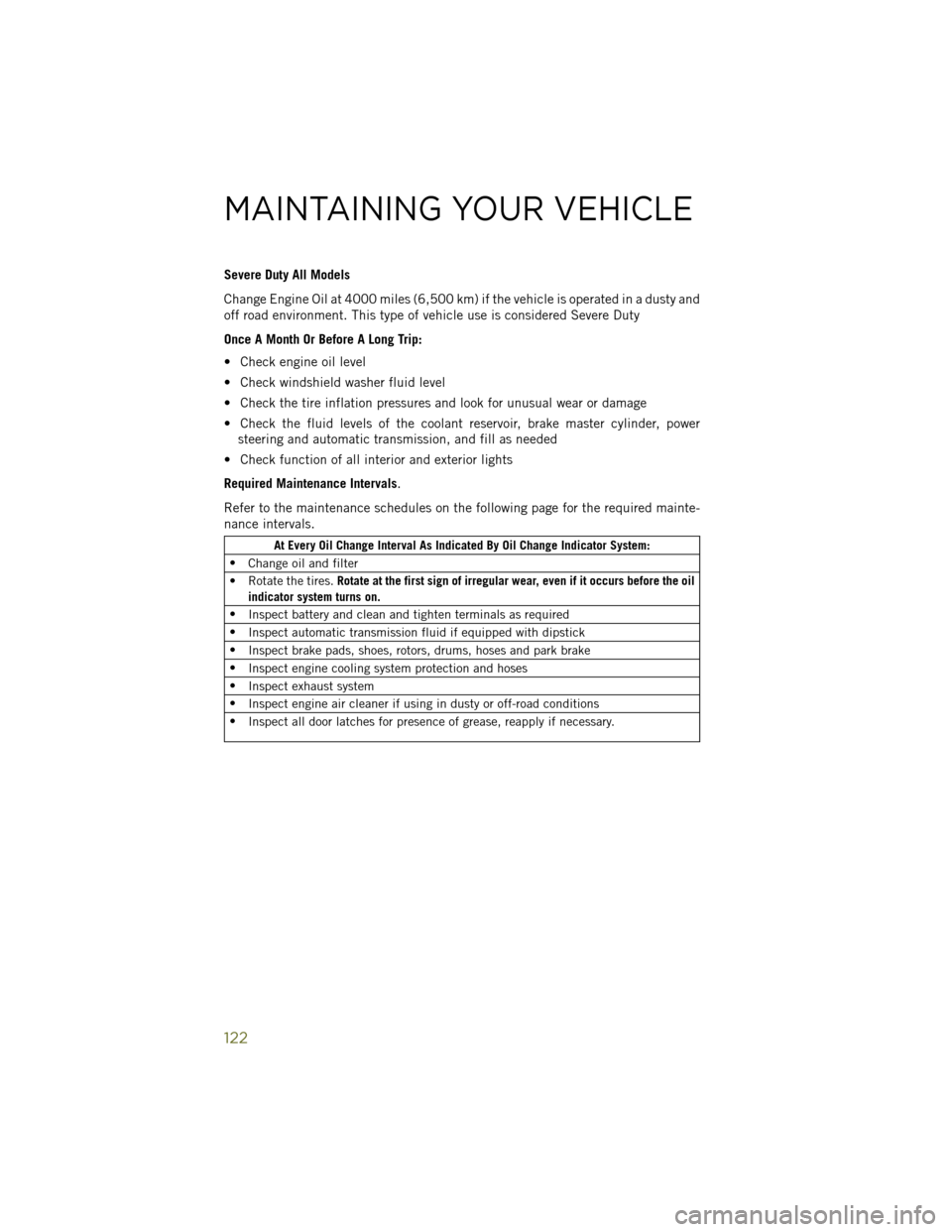
Severe Duty All Models
Change Engine Oil at 4000 miles (6,500 km) if the vehicle is operated in a dusty and
off road environment. This type of vehicle use is considered Severe Duty
Once A Month Or Before A Long Trip:
• Check engine oil level
• Check windshield washer fluid level
• Check the tire inflation pressures and look for unusual wear or damage
• Check the fluid levels of the coolant reservoir, brake master cylinder, powersteering and automatic transmission, and fill as needed
• Check function of all interior and exterior lights
Required Maintenance Intervals.
Refer to the maintenance schedules on the following page for the required mainte-
nance intervals.
At Every Oil Change Interval As Indicated By Oil Change Indicator System:
• Change oil and filter
• Rotate the tires. Rotate at the first sign of irregular wear, even if it occurs before the oil
indicator system turns on.
• Inspect battery and clean and tighten terminals as required
• Inspect automatic transmission fluid if equipped with dipstick
• Inspect brake pads, shoes, rotors, drums, hoses and park brake
• Inspect engine cooling system protection and hoses
• Inspect exhaust system
• Inspect engine air cleaner if using in dusty or off-road conditions
• Inspect all door latches for presence of grease, reapply if necessary.
MAINTAINING YOUR VEHICLE
122
Page 125 of 148
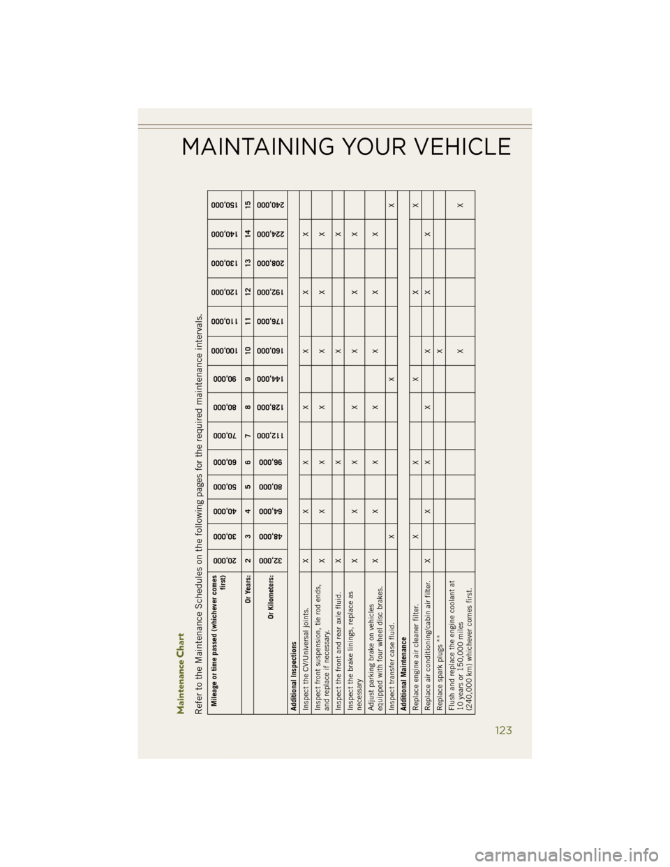
Maintenance ChartRefer to the Maintenance Schedules on the following pages for the required maintenance intervals.Mileage or time passed (whichever comesfirst)
20,000
30,000
40,000
50,000
60,000
70,000
80,000
90,000
100,000
110,000
120,000
130,000
140,000
150,000
Or Years: 2 3 4 5 6 7 8 9 10 11 12 13 14 15
Or Kilometers:
32,000
48,000
64,000
80,000
96,000
112,000
128,000
144,000
160,000
176,000
192,000
208,000
224,000
240,000
Additional Inspections
Inspect the CV/Universal joints. X X X X X X X
Inspect front suspension, tie rod ends,
and replace if necessary. XXX X X X X
Inspect the front and rear axle fluid. X X X X
Inspect the brake linings, replace as
necessary XXX X X X X
Adjust parking brake on vehicles
equipped with four wheel disc brakes. XXX X X X X
Inspect transfer case fluid. X X X
Additional Maintenance
Replace engine air cleaner filter. X X X X X
Replace air conditioning/cabin air filter. X X X X X X X
Replace spark plugs ** X
Flush and replace the engine coolant at
10 years or 150,000 miles
(240,000 km) whichever comes first. XX
MAINTAINING YOUR VEHICLE
123
Page 129 of 148
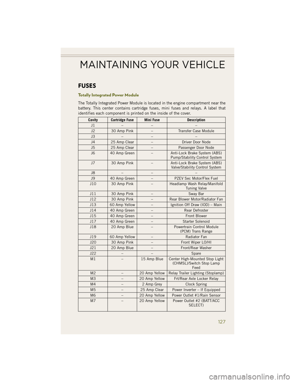
FUSES
Totally Integrated Power Module
The Totally Integrated Power Module is located in the engine compartment near the
battery. This center contains cartridge fuses, mini fuses and relays. A label that
identifies each component is printed on the inside of the cover.
Cavity Cartridge Fuse Mini FuseDescription
J1 –– –
J2 30 Amp Pink – Transfer Case Module
J3 –– –
J4 25 Amp Clear – Driver Door Node
J5 25 Amp Clear – Passenger Door Node
J6 40 Amp Green – Anti-Lock Brake System (ABS) Pump/Stability Control System
J7 30 Amp Pink – Anti-Lock Brake System (ABS) Valve/Stability Control System
J8 –– –
J9 40 Amp Green – PZEV Sec Motor/Flex Fuel
J10 30 Amp Pink – Headlamp Wash Relay/Manifold Tuning Valve
J11 30 Amp Pink – Sway Bar
J12 30 Amp Pink – Rear Blower Motor/Radiator Fan
J13 60 Amp Yellow – Ignition Off Draw (IOD) – Main
J14 40 Amp Green – Rear Defroster
J15 40 Amp Green – Front Blower
J17 40 Amp Green – Starter Solenoid
J18 20 Amp Blue – Powertrain Control Module
(PCM) Trans Range
J19 60 Amp Yellow – Radiator Fan
J20 30 Amp Pink – Front Wiper LO/HI
J21 20 Amp Blue – Front/Rear Washer
J22 –– Spare
M1 – 15 Amp Blue Center High-Mounted Stop Light
(CHMSL)/Switch Stop LampFeed
M2 – 20 Amp Yellow Relay Trailer Lighting (Stoplamp)
M3 – 20 Amp Yellow Frt/Rear Axle Locker Relay
M4 – 2 Amp Grey Clock Spring
M5 – 25 Amp Clear Power Inverter – If Equipped
M6 – 20 Amp Yellow Power Outlet #1/Rain Sensor
M7 – 20 Amp Yellow Power Outlet #2 (BATT/ACC
SELECT)
MAINTAINING YOUR VEHICLE
127
Page 131 of 148
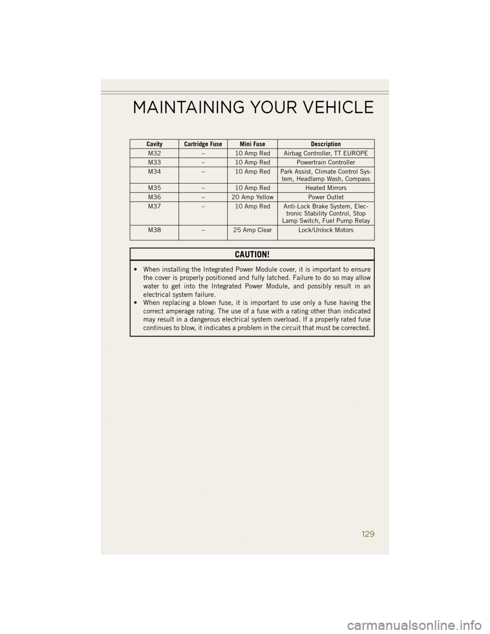
Cavity Cartridge Fuse Mini FuseDescription
M32 – 10 Amp Red Airbag Controller, TT EUROPE
M33 – 10 Amp Red Powertrain Controller
M34 – 10 Amp Red Park Assist, Climate Control Sys-
tem, Headlamp Wash, Compass
M35 – 10 Amp Red Heated Mirrors
M36 – 20 Amp Yellow Power Outlet
M37 – 10 Amp Red Anti-Lock Brake System, Elec-
tronic Stability Control, Stop
Lamp Switch, Fuel Pump Relay
M38 – 25 Amp Clear Lock/Unlock Motors
CAUTION!
• When installing the Integrated Power Module cover, it is important to ensure
the cover is properly positioned and fully latched. Failure to do so may allow
water to get into the Integrated Power Module, and possibly result in an
electrical system failure.
• When replacing a blown fuse, it is important to use only a fuse having the
correct amperage rating. The use of a fuse with a rating other than indicated
may result in a dangerous electrical system overload. If a properly rated fuse
continues to blow, it indicates a problem in the circuit that must be corrected.
MAINTAINING YOUR VEHICLE
129
Page 133 of 148
WARNING!
• Overloading of your tires is dangerous. Overloading can cause tire failure,affect vehicle handling, and increase your stopping distance. Use tires of the
recommended load capacity for your vehicle. Never overload them.
• Improperly inflated tires are dangerous and can cause collisions. Under-
inflation is the leading cause of tire failure and may result in severe cracking,
component separation, or “blow out”. Over-inflation reduces a tire’s ability to
cushion shock. Objects on the road and chuck holes can cause damage that
results in tire failure. Unequal tire pressures can cause steering problems. You
could lose control of your vehicle. Over-inflated or under-inflated tires can
affect vehicle handling and can fail suddenly, resulting in loss of vehicle
control.
WHEEL AND WHEEL TRIM CARE
All wheels and wheel trim, especially aluminum and chrome plated wheels, should
be cleaned regularly with a mild soap and water to prevent corrosion.
To remove heavy soil and/or excessive brake dust, use MOPAR
®Wheel Cleaner or
equivalent or select a non-abrasive, non-acidic cleaner.
CAUTION!
Do not use scouring pads, steel wool, a bristle brush, or metal polishes. Do not use
oven cleaner. These products may damage the wheel's protective finish. Avoid
automatic car washes that use acidic solutions or harsh brushes that may damage
the wheel's protective finish. Only MOPAR
®Wheel Cleaner or equivalent is
recommended.
EXTERIOR BULBS
Bulb Number LIGHT BULBS – Exterior
3157 Backup, Tail, Stop, Turn Lamp
LED (*) Center High-Mounted Stop Lamp (CHMSL)
PSX24W Fog Lamp – If Equipped
3157NA Front Park/Turn Signal
168 Front Side Marker
H13 Headlamp – Low Beam
194 License Lamp
* CHMSL is not serviceable. It is a LED lamp. To replace the LED, the entire CHMSL
assembly must be replaced.
MAINTAINING YOUR VEHICLE
131
Page 139 of 148
Airbag..................13
Air Conditioning ............30
Air Recirculation ............30
Alarm Arm The System ..........11
Disarm The System ........12
Vehicle Security Alarm ......11
Alarm (Security Alarm) .........11
Antifreeze (Engine Coolant) .....119
Anti-Lock Warning Light .......103
Assistance Towing ..........100
Audio Jack ........49, 52, 55, 60
Audio Settings ........48, 51, 54
Audio Systems (Radio) .........48
Automatic Headlights .........24
Automatic Temperature Control (ATC) ............30
Break-In Recommendations, New Vehicle .............24
Bulb Replacement ..........131
Calibration, Compass .........89
Capacities, Fluid ...........119
CD (Compact Disc) Player . .49, 52, 55
Change Oil Indicator .........104
Changing A Flat Tire .........106
Charging System Light ........103
Child Restraints Car Seat ...............14
Child Restraints ..........14
Child Seat Installation . . . .16, 17
Installing Child Restraints Using
The Vehicle Seat Belt .....16, 17
Lower Anchors And Tethers
For Children ..........14, 16
Using The Top Tether
Anchorage ..............16
Child Seat ................16
Climate Control .............30
Clock Setting .......48, 50, 53, 56
Cluster Warning/Indicator Lights Anti-Lock Brake (ABS) Light . .103
Charging System Light .....103
Electronic Throttle Control (ETC)
Indicator Light ..........103
Malfunction Indicator
Light (MIL) ............102 Oil Pressure Warning Light . . .103
Tire Pressure Monitoring System
(TPMS) Light
...........100
Compass Calibration ..........89
Cooling System Coolant Capacity .........119
Selection of Coolant
(Antifreeze) ........... .119
Cruise
Control (Speed Control) ....27
Customer Assistance .........132
Defects, Reporting ..........133
Dimmer Control .............25
Dimmer Switch, Headlight ......25
Disabled Vehicle Towing .......100
Disarming, Security System ......12
Door Locks ...............10
Driver Cockpit ............6,47
ECO ...................89
Electronic Speed Control (Cruise Control) ...........27
Electronic Stability Control (ESC) . .100
Electronic Stability Control (ESC) OFF Indicator ..............103
Electronic Throttle Control Warning Light ...........103
Electronic Vehicle Information Center (EVIC) ..........88, 90
Emergency, In Case of Brake Warning Light .......102
Jacking ..............106
Overheating ............105
Towing ...............100
Engine Break-In Recommendations . . .24
Compartment ...........118
Fuel Requirements ........119
Oil .................119
Oil Selection ...........119
Overheating ............105
Event Data Recorder .........116
Exterior Lights .............131
FAQ...................135
Flash-To-Pass ..............25
Flexible Fuel Vehicles ........121
Fluid Capacities ............119
INDEX
137