sensor JEEP WRANGLER 2015 JK / 3.G Owners Manual
[x] Cancel search | Manufacturer: JEEP, Model Year: 2015, Model line: WRANGLER, Model: JEEP WRANGLER 2015 JK / 3.GPages: 695, PDF Size: 20.64 MB
Page 66 of 695
•Knee Impact Bolsters
•Advanced Front Air Bags
•Supplemental Side Air Bags
•Front and Side Impact Sensors
•Seat Belt Pretensioners
•Seat Belt Buckle Switch
•Seat Track Position Sensors
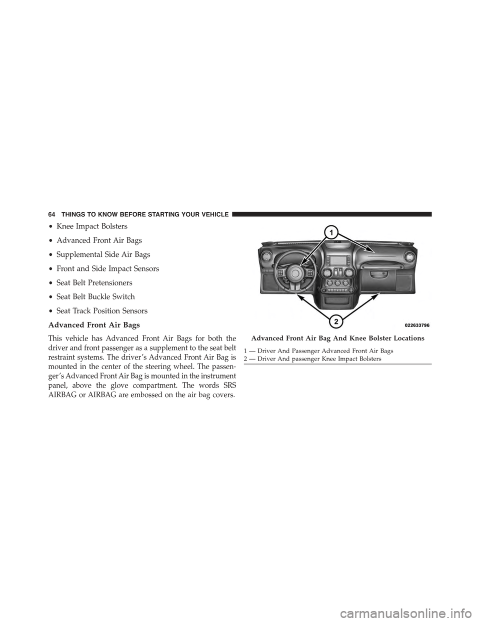
Advanced Front Air Bags
This vehicle has Advanced Front Air Bags for both the
driver and front passenger as a supplement to the seat belt
restraint systems. The driver ’s Advanced Front Air Bag is
mounted in the center of the steering wheel. The passen-
ger ’s Advanced Front Air Bag is mounted in the instrument
panel, above the glove compartment. The words SRS
AIRBAG or AIRBAG are embossed on the air bag covers.
Advanced Front Air Bag And Knee Bolster Locations
1—DriverAndPassengerAdvancedFrontAirBags2 — Driver And passenger Knee Impact Bolsters
64 THINGS TO KNOW BEFORE STARTING YOUR VEHICLE
Page 67 of 695
WARNING!
•Being too close to the steering wheel or instrument
panel during Advanced Front Air Bag deployment
could cause serious injury, including death. Air
bags need room to inflate. Sit back, comfortably
extending your arms to reach the steering wheel or
instrument panel.
•Never place a rear-facing child restraint in front of
an air bag. A deploying Passenger Advanced Front
Air Bag can cause death or serious injury to a child
12 years or younger, including a child in a rear-
facing child restraint.
•Only use a rear-facing child restraint in a vehicle
with a rear seat.
Advanced Front Air Bag Features
The Advanced Front Air Bag system has multistage
driver and front passenger air bags. This system provides
output appropriate to the severity and type of collision as
determined by the Occupant Restraint Controller (ORC),
which may receive information from the front impact
sensors or other system components.
The first stage inflator is triggered immediately during an
impact that requires air bag deployment. A low energy
output is used in less severe collisions. A higher energy
output is used for more severe collisions.
This vehicle may be equipped with driver and/or front
passenger seat track position sensors that may adjust the
inflation rate of the Advanced Front Air Bags based upon
seat position.
2
THINGS TO KNOW BEFORE STARTING YOUR VEHICLE 65
Page 69 of 695
Advanced Front Air Bag Operation
Advanced Front Air Bags are designed to provide addi-
tional protection by supplementing the seat belts. Ad-
vanced Front Air Bags are not expected to reduce the risk
of injury in rear, side, or rollover collisions. The Ad-
vanced Front Air Bags will not deploy in all frontal
collisions, including some that may produce substantial
vehicle damage — for example, some pole collisions,
truck underrides, and angle offset collisions.
On the other hand, depending on the type and location of
impact, Advanced Front Air Bags may deploy in crashes
with little vehicle front-end damage but that produce a
severe initial deceleration.
Because air bag sensors measure vehicle deceleration
over time, vehicle speed and damage by themselves are
not good indicators of whether or not an air bag should
have deployed.
Seat belts are necessary for your protection in all colli-
sions, and also are needed to help keep you in position,
away from an inflating air bag.
When the ORC detects a collision requiring the Ad-
vanced Front Air Bags, it signals the inflator units. A large
quantity of non-toxic gas is generated to inflate the
Advanced Front Air Bags.
The steering wheel hub trim cover and the upper right
side of the instrument panel separate and fold out of the
way as the air bags inflate to their full size. The Advanced
Front Air Bags fully inflate in less time than it takes to
blink your eyes. The air bags then quickly deflate while
helping to restrain the driver and front passenger.
2
THINGS TO KNOW BEFORE STARTING YOUR VEHICLE 67
Page 71 of 695
deploys through the seat seam into the space between the
occupant and the door. The SAB moves at a very high
speed and with such a high force that it could injure you
if you are not seated properly, or if items are positioned
in the area where the SAB inflates. Children are at an
even greater risk of injury from a deploying air bag.
WARNING!
Do not use accessory seat covers or place objects
between you and the Side Air Bags; the performance
could be adversely affected and/or objects could be
pushed into you, causing serious injury.
SABs are designed to activate in certain side impacts. The
Occupant Restraint Controller (“ORC”) determines
whether the deployment of the SAB in a particular
impact event is appropriate, based on the severity and
type of collision. The side impact sensors aid the ORC in
determining the appropriate response to impact events.
The system is calibrated to deploy the SAB on the impact
side of the vehicle during impacts that require SAB
occupant protection. In side impacts, the SABs deploy
independently; a left side impact deploys the left SAB
only and a right side impact deploys the right side SAB
only. Vehicle damage by itself is not a good indicator of
whether or not SABs should have deployed.
The SABs will not deploy in all side collisions, including
some collisions at certain angles, or some side collisions
that do not impact the area of the passenger compart-
ment.
SABs are a supplement to the seat belt restraint system.
SABs deploy in less time than it takes to blink your eyes.
Occupants, including children, who are up against or very
close to SABs can be seriously injured or killed. Occupants,
including children, should never lean on or sleep against
the door, side windows, or area where the SABs inflate,
even if they are in an infant or child restraint.
2
THINGS TO KNOW BEFORE STARTING YOUR VEHICLE 69
Page 114 of 695
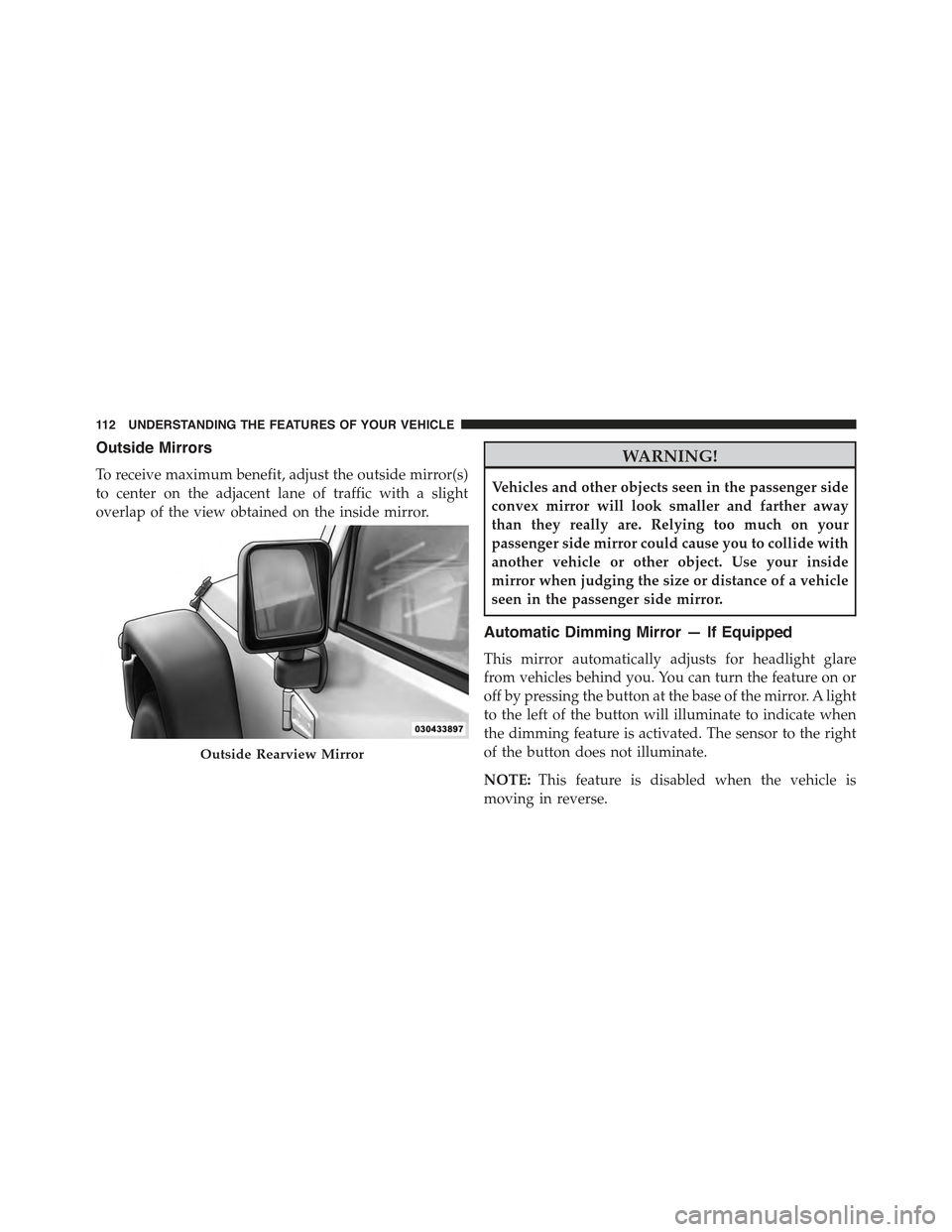
Outside Mirrors
To receive maximum benefit, adjust the outside mirror(s)
to center on the adjacent lane of traffic with a slight
overlap of the view obtained on the inside mirror.
WARNING!
Vehicles and other objects seen in the passenger side
convex mirror will look smaller and farther away
than they really are. Relying too much on your
passenger side mirror could cause you to collide with
another vehicle or other object. Use your inside
mirror when judging the size or distance of a vehicle
seen in the passenger side mirror.
Automatic Dimming Mirror — If Equipped
This mirror automatically adjusts for headlight glare
from vehicles behind you. You can turn the feature on or
off by pressing the button at the base of the mirror. A light
to the left of the button will illuminate to indicate when
the dimming feature is activated. The sensor to the right
of the button does not illuminate.
NOTE:This feature is disabled when the vehicle is
moving in reverse.
Outside Rearview Mirror
11 2 U N D E R S TA N D I N G T H E F E AT U R E S O F Y O U R V E H I C L E
Page 321 of 695
maintain correct tire pressure, even if under-inflation has
not reached the level to trigger illumination of the TPMS
low tire pressure telltale.
Your vehicle has also been equipped with a TPMS
malfunction indicator to indicate when the system is not
operating properly. The TPMS malfunction indicator is
combined with the low tire pressure telltale. When the
system detects a malfunction, the telltale will flash for
approximately one minute and then remain continuously
illuminated. This sequence will continue upon subse-
quent vehicle start-ups as long as the malfunction exists.
When the malfunction indicator is illuminated, the sys-
tem may not be able to detect or signal low tire pressure
as intended. TPMS malfunctions may occur for a variety
of reasons, including the installation of replacement or
alternate tires or wheels on the vehicle that prevent the
TPMS from functioning properly. Always check the
TPMS malfunction telltale after replacing one or more
tires or wheels on your vehicle, to ensure that the
replacement or alternate tires and wheels allow the TPMS
to continue to function properly.
CAUTION!
The TPMS has been optimized for the original
equipment tires and wheels. TPMS pressures and
warning have been established for the tire size
equipped on your vehicle. Undesirable system opera-
tion or sensor damage may result when using re-
placement equipment that is not of the same size,
type, and/or style. Aftermarket wheels can cause
sensor damage. Do not use tire sealant from a can or
balance beads if your vehicle is equipped with a
TPMS, as damage to the sensors may result.
4
UNDERSTANDING YOUR INSTRUMENT PANEL 319
Page 328 of 695
•Magnetic materials should be kept away from the top
of the center of the instrument panel. This is where the
compass sensor is located.
Average Fuel Economy / Distance To Empty (DTE)
/ Elapsed Time
•Average Fuel Economy
Shows the average fuel economy since the last reset.
When the fuel economy is reset, the digits will go blank
while the history information is erased. The averaging
will restart when enough new distance and fuel data is
accumulated.
•Distance To Empty (DTE)
Shows the estimated distance that can be traveled with
the fuel remaining in the tank. This estimated distance is
determined by a weighted average of the instantaneous
and average fuel economy, according to the current fuel
tank level. DTE cannot be reset.
•Elapsed Time
Shows the total elapsed time of travel since the last reset.
Elapsed time will increment when the ignition switch is
in the RUN or START positions. The elapsed timer
displays minutes:seconds. After 59minutes:59seconds, it
displays hours:minutes:seconds.
Trip Conditions
Trip Odometer (ODO) / ECO (Fuel Saver Indicator)
— If Equipped
This display shows the distance traveled since the last
reset. Push and release the right button (on the instru-
ment cluster) to switch from odometer to Trip A or Trip B
or to ECO. Push and hold the right button while the
odometer/trip odometer is displayed to reset.
326 UNDERSTANDING YOUR INSTRUMENT PANEL
Page 337 of 695
NOTE:Magnetic materials should be kept away from
the top of the instrument panel; this is where the compass
sensor is located.
To Change The Compass Variance:
1. Turn the ignition switch RUN (it is not necessary to
start the engine).
2. Push the MENU button until Personal Settings
(Customer-Programmable Features) displays in the
EVIC.
3. Push the DOWN button until “Compass Variance”
message and the last variance zone number displays
in the EVIC.
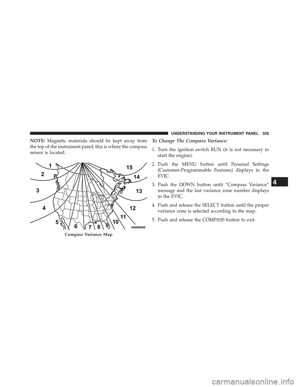
4. Push and release the SELECT button until the proper
variance zone is selected according to the map.
5. Push and release the COMPASS button to exit.
Compass Variance Map
4
UNDERSTANDING YOUR INSTRUMENT PANEL 335
Page 479 of 695
WARNING!(Continued)
capabilities of an ERM-equipped vehicle must never
be exploited in a reckless or dangerous manner
which could jeopardize the user’s safety or the safety
of others.
Electronic Stability Control (ESC)
This system enhances directional control and stability of
the vehicle under various driving conditions. The ESC
corrects for over/under steering of the vehicle by apply-
ing the brake of the appropriate wheel to assist in
counteracting the over/under steer condition. Engine
power may also be reduced to help the vehicle maintain
the desired path.
ESC uses sensors in the vehicle to determine the vehicle
path intended by the driver and compares it to the actual
path of the vehicle. When the actual path does not match
the intended path, ESC applies the brake of the appro-
priate wheel to assist in counteracting the oversteer or
understeer condition.
•Oversteer - when the vehicle is turning more than
appropriate for the steering wheel position.
•Understeer - when the vehicle is turning less than
appropriate for the steering wheel position.
The “ESC Activation/Malfunction Indicator Light” (lo-
cated in the instrument cluster), starts to flash as soon as
the tires lose traction and the ESC system becomes active.
The “ESC Activation/Malfunction Indicator Light” also
flashes when TCS is active. If the “ESC Activation/
Malfunction Indicator Light” begins to flash during ac-
celeration, ease up on the accelerator and apply as little
throttle as possible. Be sure to adapt your speed and
driving to the prevailing road conditions.
5
STARTING AND OPERATING 477
Page 486 of 695
NOTE:
•The “ESC Off Indicator Light” and the “ESC
Activation/Malfunction Indicator Light” come on mo-
mentarily each time the ignition switch is turned to the
ON/RUN position.
•Each time the ignition is cycled to the ON/RUN
position, the ESC system will be ON even if it was
cycled off previously, except for when the vehicle is
started while in 4L Range.
•The ESC system will make buzzing or clicking sounds
when it is active. This is normal; the sounds will stop
when ESC becomes inactive following the maneuver
that caused the ESC activation.
The “ESC OFF Indicator Light” indicates the
Electronic Stability Control (ESC) is partially
off or full off.
Trailer Sway Control (TSC)
TSC uses sensors in the vehicle to recognize an exces-
sively swaying trailer and will take the appropriate
actions to attempt to stop the sway. The system may
reduce engine power and apply the brake of the appro-
priate wheel(s) to counteract the sway of the trailer. TSC
will become active automatically once an excessively
swaying trailer is recognized. TSC cannot stop all trailers
from swaying. Always use caution when towing a trailer
and follow the tongue weight recommendations. Refer to
“Trailer Towing” in “Starting and Operating” for further
information. When TSC is functioning, the “ESC
Activation/Malfunction Indicator Light” will flash, the
engine power may be reduced and you may feel the
brakes being applied to individual wheels to attempt to
stop the trailer from swaying. TSC is disabled when the
ESC system is in the#ESC Partial Off#or#ESC Full Off#
modes.
484 STARTING AND OPERATING