JEEP WRANGLER 2015 JK / 3.G Owner's Manual
Manufacturer: JEEP, Model Year: 2015, Model line: WRANGLER, Model: JEEP WRANGLER 2015 JK / 3.GPages: 156, PDF Size: 23.54 MB
Page 21 of 156
4. To lock the seat belt, pull down on the shoulder part of the belt until you have
pulled all the seat belt webbing out of the retractor. Then, allow the webbing to
retract back into the retractor. As the webbing retracts, you will hear a clicking
sound. This means the seat belt is now in the Automatic Locking mode.
5. Try to pull the webbing out of the retractor. If it is locked, you should not be able
to pull out any webbing. If the retractor is not locked, repeat the last step.
6. Finally, pull up on any extra webbing to tighten the lap portion around the child
restraint while you push the child restraint rearward and downward into the
vehicle seat.
7. If the child restraint has a top tether strap and the seating position has a top tether
anchorage, connect the tether strap to the anchorage and tighten the tether strap.
See below for directions to attach a tether anchor.
8. Test that the child restraint is installed tightly by pulling back and forth on the
child seat at the belt path. It should not move more than 1 inch (25.4 mm) in any
direction.
Installing The Top Tether Strap (With Either Lower Anchors Or Vehicle Seat Belt):
When installing a forward-facing child restraint, always secure the top tether strap,
up to the tether anchor weight limit, whether the child restraint is installed with the
lower anchors or the vehicle seat belt.
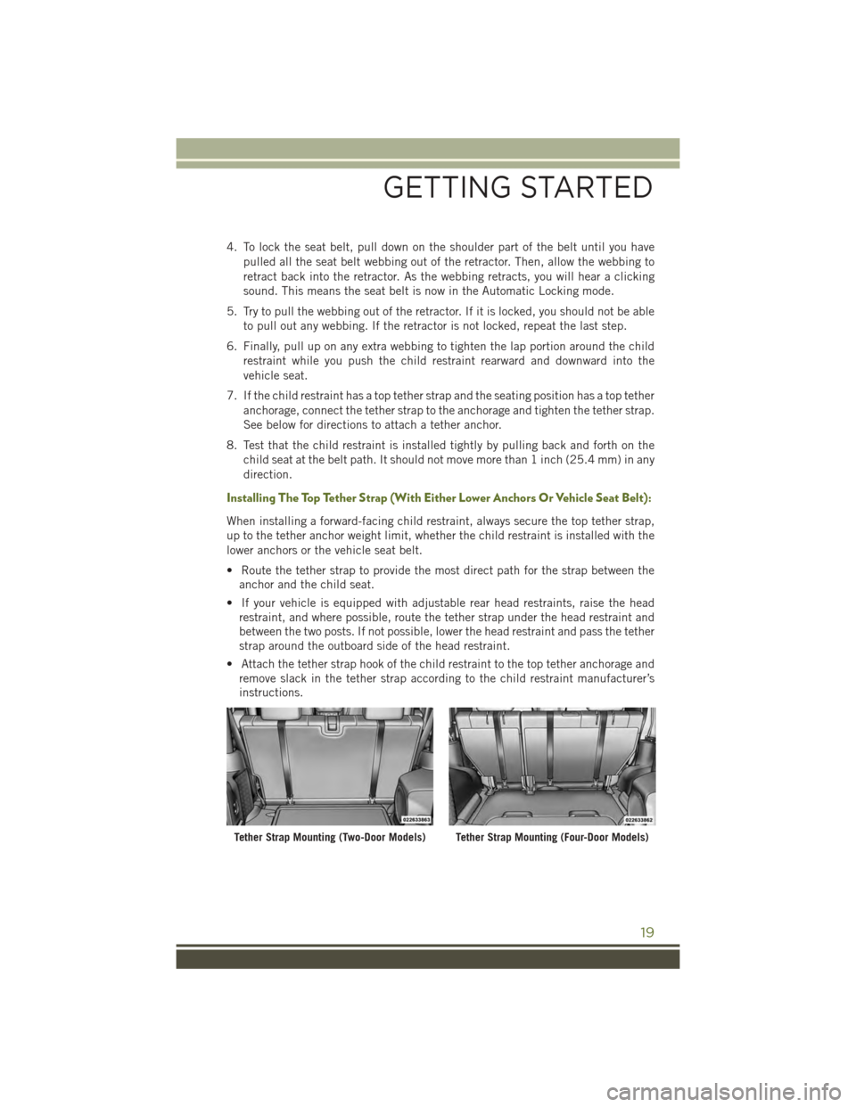
• Route the tether strap to provide the most direct path for the strap between the
anchor and the child seat.
• If your vehicle is equipped with adjustable rear head restraints, raise the head
restraint, and where possible, route the tether strap under the head restraint and
between the two posts. If not possible, lower the head restraint and pass the tether
strap around the outboard side of the head restraint.
• Attach the tether strap hook of the child restraint to the top tether anchorage and
remove slack in the tether strap according to the child restraint manufacturer’s
instructions.
Tether Strap Mounting (Two-Door Models)Tether Strap Mounting (Four-Door Models)
GETTING STARTED
19
Page 22 of 156
WARNING!
• In a collision, an unrestrained child, even a tiny baby, can become a projectile
inside the vehicle. The force required to hold even an infant on your lap could
become so great that you could not hold the child, no matter how strong you
are. The child and others could be severely injured or killed. Any child riding in
your vehicle should be in a proper restraint for the child's size.
• Rearward-facing child seats must never be used in the front seat of a vehicle
with a front passenger air bag. An air bag deployment could cause severe injury
or death to infants in this position.
• Only use a rearward-facing child restraint in a vehicle with a rear seat.
• Improper installation of a child restraint to the LATCH anchorages can lead to
failure of an infant or child restraint. The child could be severely injured or
killed. Follow the manufacturer’s directions exactly when installing an infant or
child restraint.
• An incorrectly anchored tether strap could lead to increased head motion and
possible injury to the child. Use only the anchor positions directly behind the
child seat to secure a child restraint top tether strap.
• If your vehicle is equipped with a split rear seat, make sure the tether strap
does not slip into the opening between the seatbacks as you remove slack in
the strap.
HEAD RESTRAINTS
Head restraints are designed to reduce the risk of injury by restricting head
movement in the event of a rear impact. Head restraints should be adjusted so that
the top of the head restraint is located above the top of your ear.
WARNING!
The head restraints for all occupants must be properly installed and adjusted prior
to operating the vehicle or occupying a seat. Head restraints should never be
adjusted while the vehicle is in motion. Driving a vehicle with the head restraints
improperly adjusted or removed could cause serious injury or death in the event of
a collision.
GETTING STARTED
20
Page 23 of 156
Front Head Restraints
To raise the head restraint, pull upward on the head restraint. To lower the head
restraint, press the adjustment button, located on the base of the head restraint, and
push downward on the head restraint.
Rear Head Restraints—2DoorModel
The rear seat is equipped with adjustable head restraints. To raise the head restraint,
pull upward on the head restraint. To lower the head restraint, press the adjustment
button, located on the base of the head restraint, and push downward on the head
restraint.
Rear Head Restraints—4DoorModel
The rear seat is equipped with nonadjustable head restraints.
FRONT SEATS
Manual Seat Adjustment
Forward/Rearward
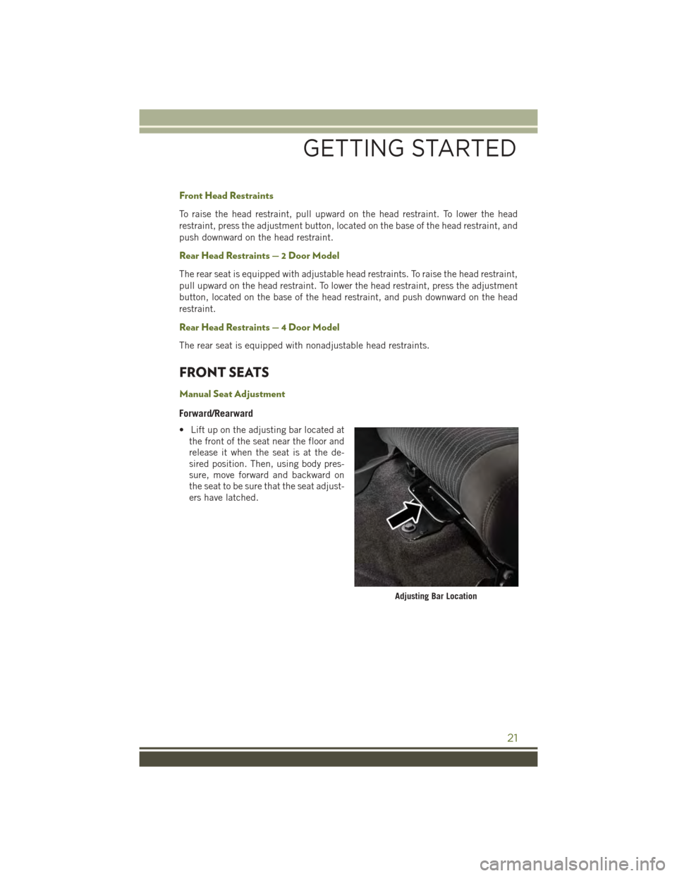
• Lift up on the adjusting bar located at
the front of the seat near the floor and
release it when the seat is at the de-
sired position. Then, using body pres-
sure, move forward and backward on
the seat to be sure that the seat adjust-
ers have latched.
Adjusting Bar Location
GETTING STARTED
21
Page 24 of 156
Height Adjustment
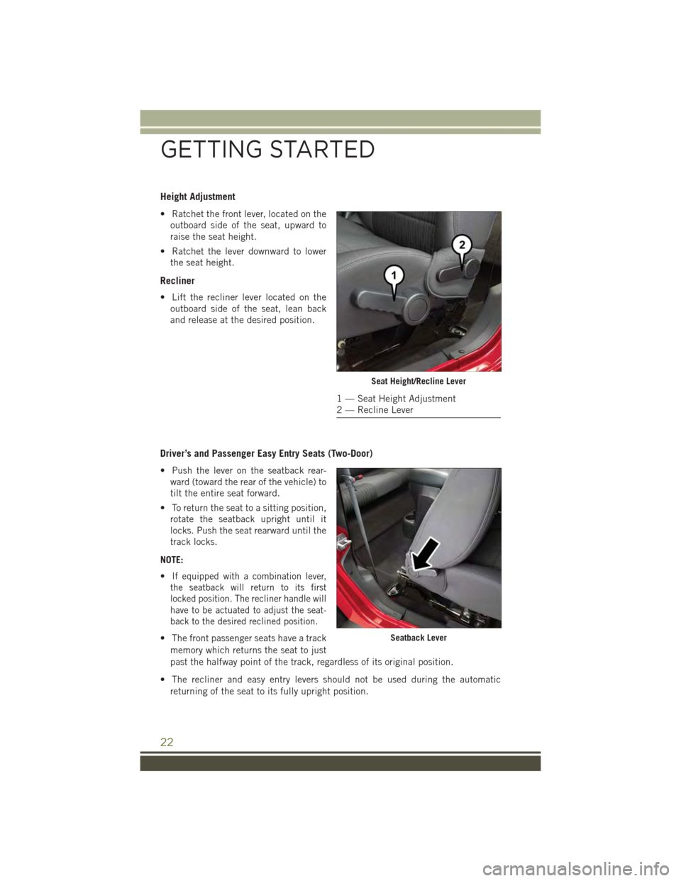
• Ratchet the front lever, located on the
outboard side of the seat, upward to
raise the seat height.
• Ratchet the lever downward to lower
the seat height.
Recliner
• Lift the recliner lever located on the
outboard side of the seat, lean back
and release at the desired position.
Driver’s and Passenger Easy Entry Seats (Two-Door)
• Push the lever on the seatback rear-
ward (toward the rear of the vehicle) to
tilt the entire seat forward.
• To return the seat to a sitting position,
rotate the seatback upright until it
locks. Push the seat rearward until the
track locks.
NOTE:
•If equipped with a combination lever,
the seatback will return to its first
locked position. The recliner handle will
have to be actuated to adjust the seat-
back to the desired reclined position.
• The front passenger seats have a track
memory which returns the seat to just
past the halfway point of the track, regardless of its original position.
• The recliner and easy entry levers should not be used during the automatic
returning of the seat to its fully upright position.
Seat Height/Recline Lever
1 — Seat Height Adjustment2 — Recline Lever
Seatback Lever
GETTING STARTED
22
Page 25 of 156
WARNING!
•Adjusting a seat while the vehicle is moving is dangerous. The sudden movement
of the seat could cause you to lose control. The seat belt might not be properly
adjusted, and you could be severely injured or killed. Only adjust a seat while the
vehicle is parked.
• Do not ride with the seatback reclined so that the seat belt is no longer resting
against your chest. In a collision, you could slide under the seat belt and be
severely injured or killed. Use the recliner only when the vehicle is parked.
REAR SEATS
Folding Rear Seat
• Be sure that the front seats are fully upright and positioned forward. This will allow
the rear seat to fold down easily.
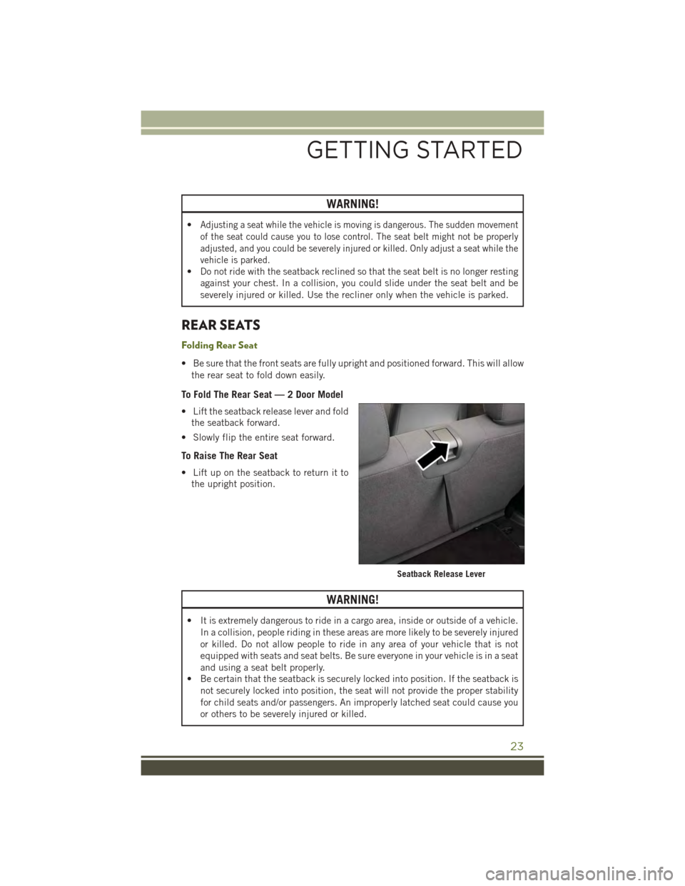
To Fold The Rear Seat — 2 Door Model
• Lift the seatback release lever and fold
the seatback forward.
• Slowly flip the entire seat forward.
To Raise The Rear Seat
• Lift up on the seatback to return it to
the upright position.
WARNING!
• It is extremely dangerous to ride in a cargo area, inside or outside of a vehicle.
In a collision, people riding in these areas are more likely to be severely injured
or killed. Do not allow people to ride in any area of your vehicle that is not
equipped with seats and seat belts. Be sure everyone in your vehicle is in a seat
and using a seat belt properly.
• Be certain that the seatback is securely locked into position. If the seatback is
not securely locked into position, the seat will not provide the proper stability
for child seats and/or passengers. An improperly latched seat could cause you
or others to be severely injured or killed.
Seatback Release Lever
GETTING STARTED
23
Page 26 of 156
TILT STEERING COLUMN
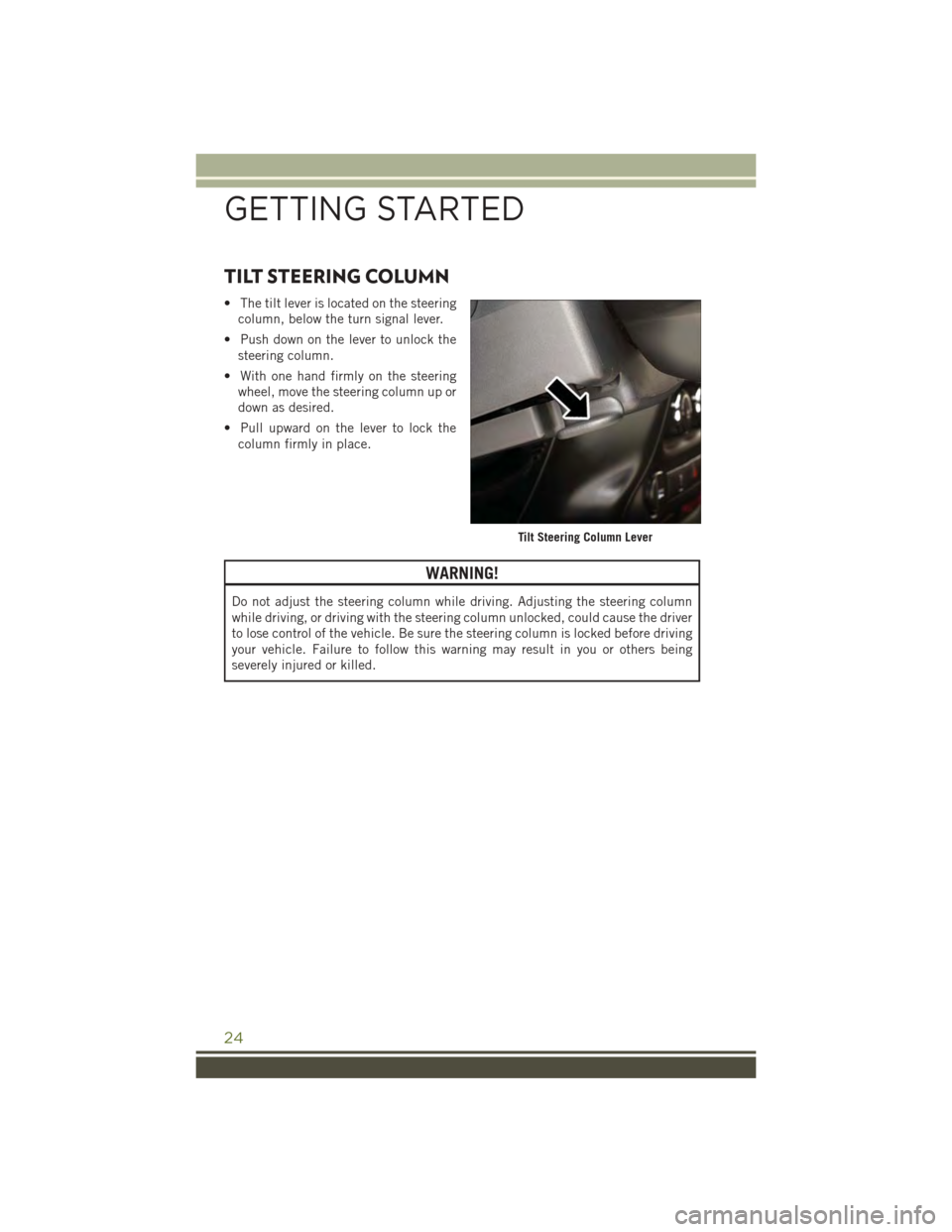
• The tilt lever is located on the steering
column, below the turn signal lever.
• Push down on the lever to unlock the
steering column.
• With one hand firmly on the steering
wheel, move the steering column up or
down as desired.
• Pull upward on the lever to lock the
column firmly in place.
WARNING!
Do not adjust the steering column while driving. Adjusting the steering column
while driving, or driving with the steering column unlocked, could cause the driver
to lose control of the vehicle. Be sure the steering column is locked before driving
your vehicle. Failure to follow this warning may result in you or others being
severely injured or killed.
Tilt Steering Column Lever
GETTING STARTED
24
Page 27 of 156
HEATED SEATS
Front Heated Seats
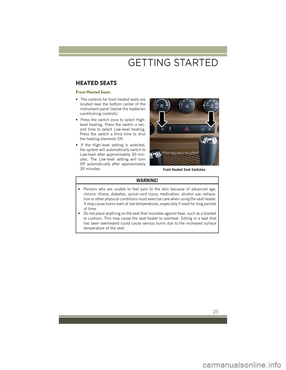
• The controls for front heated seats are
located near the bottom center of the
instrument panel (below the heater/air
conditioning controls).
• Press the switch once to select High-
level heating. Press the switch a sec-
ond time to select Low-level heating.
Press the switch a third time to shut
the heating elements Off.
• If the High-level setting is selected,
the system will automatically switch to
Low-level after approximately 30 min-
utes. The Low-level setting will turn
Off automatically after approximately
30 minutes.
WARNING!
• Persons who are unable to feel pain to the skin because of advanced age,
chronic illness, diabetes, spinal cord injury, medication, alcohol use, exhaus-
tion or other physical conditions must exercise care when using the seat heater.
It may cause burns even at low temperatures, especially if used for long periods
of time.
• Do not place anything on the seat that insulates against heat, such as a blanket
or cushion. This may cause the seat heater to overheat. Sitting in a seat that
has been overheated could cause serious burns due to the increased surface
temperature of the seat.
Front Heated Seat Switches
GETTING STARTED
25
Page 28 of 156
ENGINE BREAK-IN RECOMMENDATIONS
A long break-in period is not required for the engine and drivetrain (transmission and
axle) in your vehicle.
Drive moderately during the first 300 miles (500 km). After the initial 60 miles (100 km),
speeds up to 50 or 55 mph (80 or 90 km/h) are desirable.
While cruising, brief full-throttle acceleration within the limits of local traffic laws
contributes to a good break-in. Wide-open throttle acceleration in low gear can be
detrimental and should be avoided.
The engine oil installed in the engine at the factory is a high-quality energy
conserving type lubricant. Oil changes should be consistent with anticipated climate
conditions under which vehicle operations will occur. For the recommended viscosity
and quality grades, refer to “Maintaining Your Vehicle.”
NOTE:
A new engine may consume some oil during its first few thousand miles (kilometers) of
operation. This should be considered a normal part of the break-in and not interpreted
as an indication of an engine problem or malfunction.
CAUTION!
Never use Non-Detergent Oil or Straight Mineral Oil in the engine or damage may
result.
TURN SIGNAL/LIGHTS LEVER
Headlights/Parking Lights/Automatic
Headlights
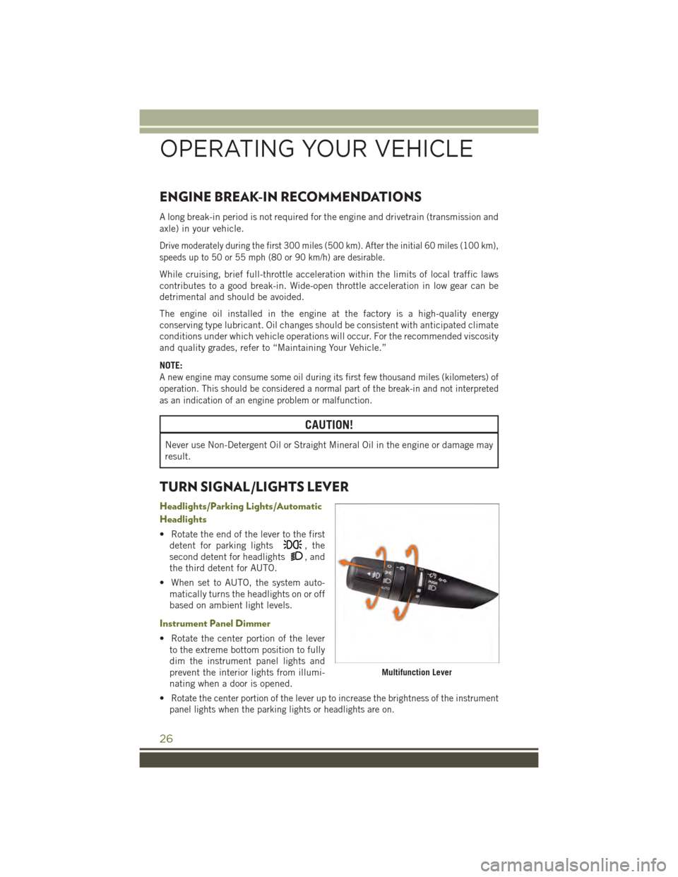
• Rotate the end of the lever to the first
detent for parking lights, the
second detent for headlights, and
the third detent for AUTO.
• When set to AUTO, the system auto-
matically turns the headlights on or off
based on ambient light levels.
Instrument Panel Dimmer
• Rotate the center portion of the lever
to the extreme bottom position to fully
dim the instrument panel lights and
prevent the interior lights from illumi-
nating when a door is opened.
•Rotate the center portion of the lever up to increase the brightness of the instrument
panel lights when the parking lights or headlights are on.
Multifunction Lever
OPERATING YOUR VEHICLE
26
Page 29 of 156
•Rotate the center portion of the lever upward to the next detent position to brighten
the odometer and radio controls when the parking lights or headlights are on.
• Rotate the center portion of the lever upward to the last detent to turn on the
interior lighting.
Flash To Pass
• Pull the lever toward you to activate the high beams. The high beams will remain
on until the lever is released.
High Beam Operation
• Push the lever forward to activate the high beams.
NOTE:
For safe driving, turn off the high beams when oncoming traffic is present to prevent
headlight glare and as a courtesy to other motorists.
Fog Lights
• Turn on the parking lights or low beam headlights and pull out the end of the lever.
Turn Signals/Lane Change Assist
Tap the lever up or down once and the turn signal (right or left) will flash three times
and automatically turn off.
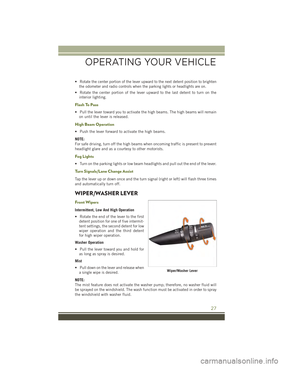
WIPER/WASHER LEVER
Front Wipers
Intermittent, Low And High Operation
• Rotate the end of the lever to the first
detent position for one of five intermit-
tent settings, the second detent for low
wiper operation and the third detent
for high wiper operation.
Washer Operation
• Pull the lever toward you and hold for
as long as spray is desired.
Mist
•Pull down on the lever and release when
a single wipe is desired.
NOTE:
The mist feature does not activate the washer pump; therefore, no washer fluid will
be sprayed on the windshield. The wash function must be activated in order to spray
the windshield with washer fluid.
Wiper/Washer Lever
OPERATING YOUR VEHICLE
27
Page 30 of 156
Rear Wiper
Wiper Operation
• Rotate the center portion of the lever forward to the first detent for rear wiper
operation.
Washer Operation
• Rotate the center portion of the lever past the first detent to activate the rear
washer.
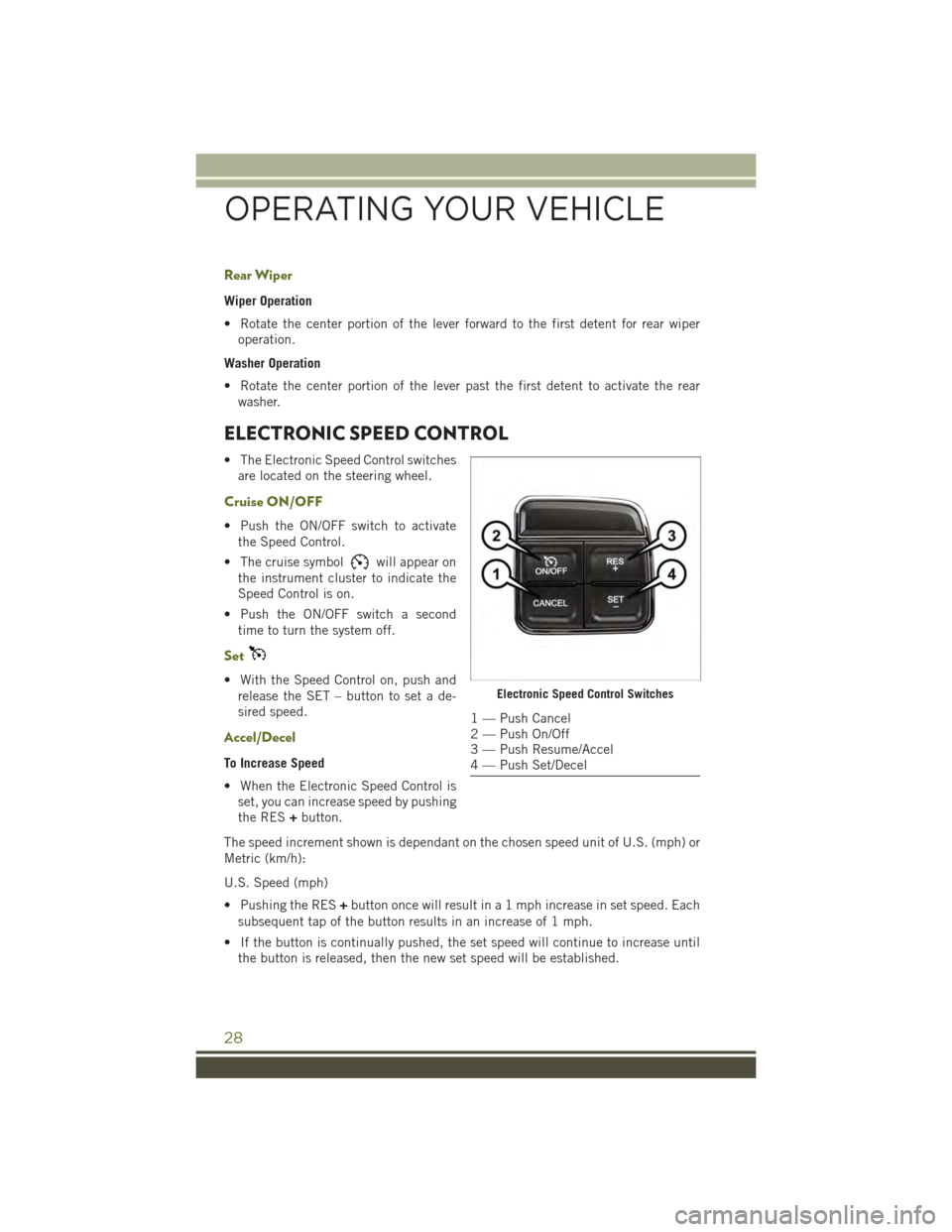
ELECTRONIC SPEED CONTROL
• The Electronic Speed Control switches
are located on the steering wheel.
Cruise ON/OFF
• Push the ON/OFF switch to activate
the Speed Control.
• The cruise symbolwill appear on
the instrument cluster to indicate the
Speed Control is on.
• Push the ON/OFF switch a second
time to turn the system off.
Set
• With the Speed Control on, push and
release the SET – button to set a de-
sired speed.
Accel/Decel
To Increase Speed
• When the Electronic Speed Control is
set, you can increase speed by pushing
the RES+button.
The speed increment shown is dependant on the chosen speed unit of U.S. (mph) or
Metric (km/h):
U.S. Speed (mph)
• Pushing the RES+button once will result in a 1 mph increase in set speed. Each
subsequent tap of the button results in an increase of 1 mph.
• If the button is continually pushed, the set speed will continue to increase until
the button is released, then the new set speed will be established.
Electronic Speed Control Switches
1 — Push Cancel2 — Push On/Off3 — Push Resume/Accel4 — Push Set/Decel
OPERATING YOUR VEHICLE
28