JEEP WRANGLER 2016 JK / 3.G User Guide
Manufacturer: JEEP, Model Year: 2016, Model line: WRANGLER, Model: JEEP WRANGLER 2016 JK / 3.GPages: 156, PDF Size: 8.82 MB
Page 131 of 156
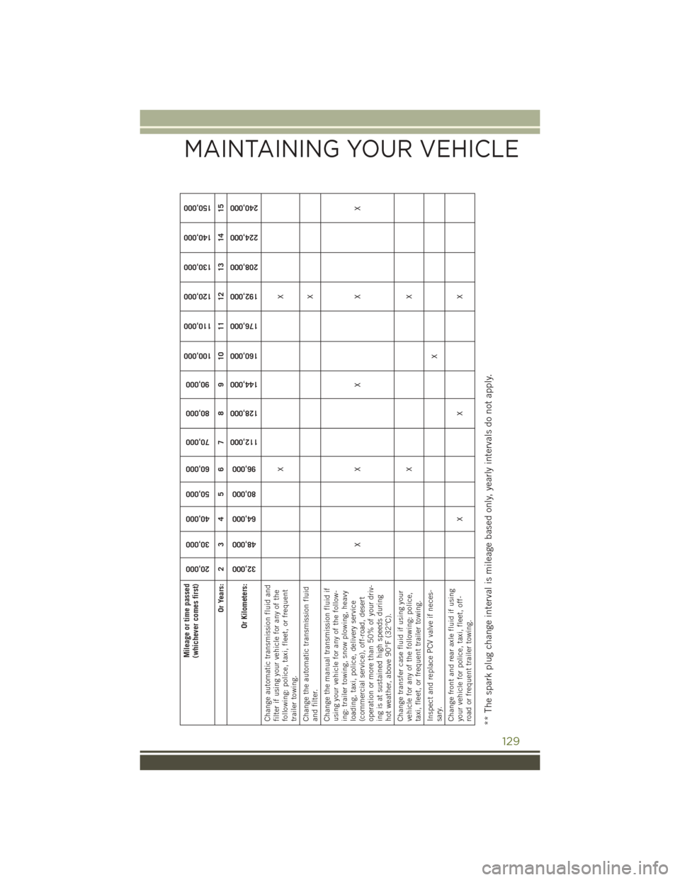
Mileage or time passed
(whichever comes first)
20,000
30,000
40,000
50,000
60,000
70,000
80,000
90,000
100,000
110,000
120,000
130,000
140,000
150,000
Or Years: 2 3 4 5 6 7 8 9 10 11 12 13 14 15
Or Kilometers:
32,000
48,000
64,000
80,000
96,000
112,000
128,000
144,000
160,000
176,000
192,000
208,000
224,000
240,000
Change automatic transmission fluid and
filter if using your vehicle for any of the
following: police, taxi, fleet, or frequent
trailer towing. XX
Change the automatic transmission fluid
and filter. X
Change the manual transmission fluid if
using your vehicle for any of the follow-
ing: trailer towing, snow plowing, heavy
loading, taxi, police, delivery service
(commercial service), off-road, desert
operation or more than 50% of your driv-
ing is at sustained high speeds during
hot weather, above 90°F (32°C). XX X X X
Change transfer case fluid if using your
vehicle for any of the following: police,
taxi, fleet, or frequent trailer towing. XX
Inspect and replace PCV valve if neces-
sary. X
Change front and rear axle fluid if using
your vehicle for police, taxi, fleet, off-
road or frequent trailer towing. XX X** The spark plug change interval is mileage based only, yearly intervals do not apply.
MAINTAINING YOUR VEHICLE
129
Page 132 of 156
WARNING!
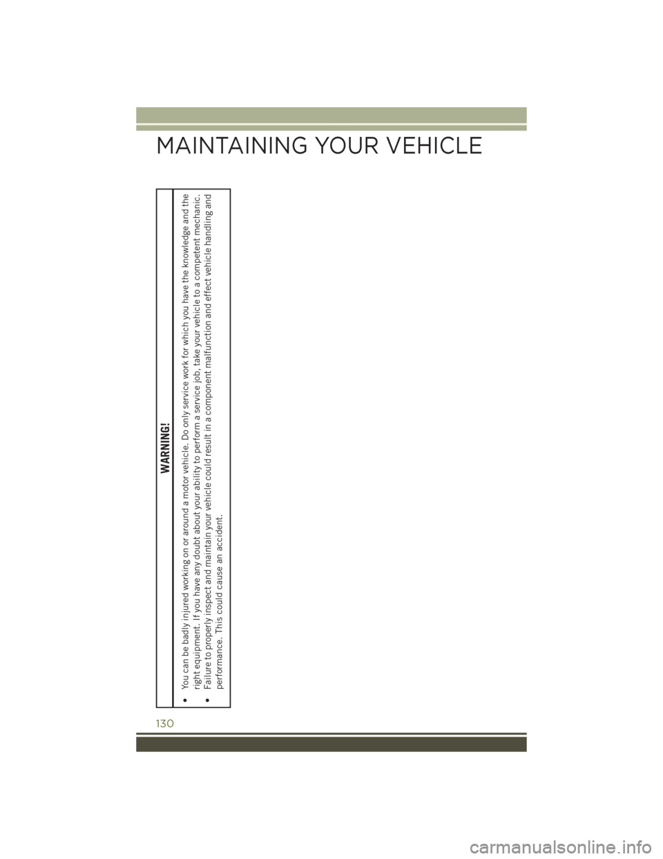
• You can be badly injured working on or around a motor vehicle. Do only service work for which you have the knowledge and theright equipment. If you have any doubt about your ability to perform a service job, take your vehicle to a competent mechanic.
• Failure to properly inspect and maintain your vehicle could result in a component malfunction and effect vehicle handling and
performance. This could cause an accident.
MAINTAINING YOUR VEHICLE
130
Page 133 of 156

MAINTENANCE RECORD
Odometer Date Signature, Autho-rized Service Center
20,000 Miles
(32,000 km) or
2 Years
30,000 Miles
(48,000 km) or
3 Years
40,000 Miles
(64,000 km) or
4 Years
50,000 Miles
(80,000 km) or
5 Years
60,000 Miles
(96,000 km) or
6 Years
70,000 Miles
(112,000 km) or
7 Years
80,000 Miles
(128,000 km) or
8 Years
Odometer Date Signature, Autho- rized Service Center
90,000 Miles
(144,000 km) or
9 Years
100,000 Miles
(160,000 km) or
10 Years
110,000 Miles
(176,000 km) or
11 Years
120,000 Miles
(192,000 km) or
12 Years
130,000 Miles
(208,000 km) or
13 Years
140,000 Miles
(224,000 km) or
14 Years
150,000 Miles
(240,000 km) or
15 Years
MAINTAINING YOUR VEHICLE
131
Page 134 of 156
FUSES
WARNING!
• When replacing a blown fuse, always use an appropriate replacement fuse withthe same amp rating as the original fuse. Never replace a fuse with another
fuse of higher amp rating. Never replace a blown fuse with metal wires or any
other material. Failure to use proper fuses may result in serious personal injury,
fire and/or property damage.
• Before replacing a fuse, make sure that the ignition is off and that all the other
services are switched off and/or disengaged.
• If the replaced fuse blows again, contact an authorized dealer.
• If a general protection fuse for safety systems (air bag system, braking system),
power unit systems (engine system, gearbox system) or steering system blows,
contact an authorized dealer.
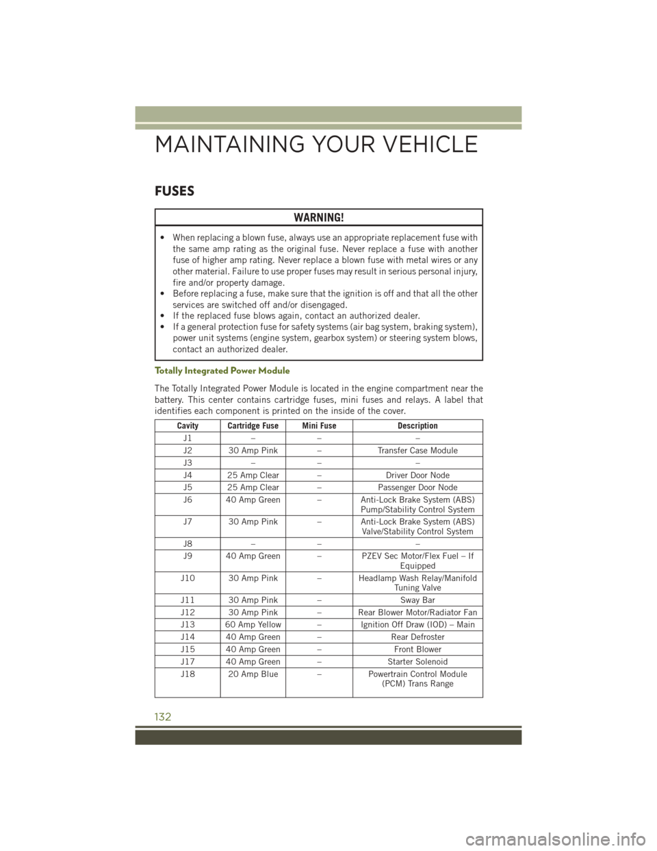
Totally Integrated Power Module
The Totally Integrated Power Module is located in the engine compartment near the
battery. This center contains cartridge fuses, mini fuses and relays. A label that
identifies each component is printed on the inside of the cover.
Cavity Cartridge Fuse Mini Fuse Description
J1 –– –
J2 30 Amp Pink – Transfer Case Module
J3 –– –
J4 25 Amp Clear – Driver Door Node
J5 25 Amp Clear – Passenger Door Node
J6 40 Amp Green – Anti-Lock Brake System (ABS) Pump/Stability Control System
J7 30 Amp Pink – Anti-Lock Brake System (ABS) Valve/Stability Control System
J8 –– –
J9 40 Amp Green – PZEV Sec Motor/Flex Fuel – If Equipped
J10 30 Amp Pink – Headlamp Wash Relay/Manifold Tuning Valve
J11 30 Amp Pink – Sway Bar
J12 30 Amp Pink – Rear Blower Motor/Radiator Fan
J13 60 Amp Yellow – Ignition Off Draw (IOD) – Main
J14 40 Amp Green – Rear Defroster
J15 40 Amp Green – Front Blower
J17 40 Amp Green – Starter Solenoid
J18 20 Amp Blue – Powertrain Control Module
(PCM) Trans Range
MAINTAINING YOUR VEHICLE
132
Page 135 of 156
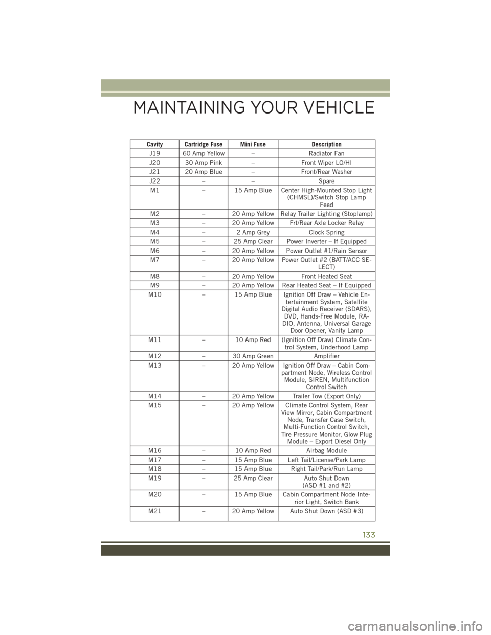
Cavity Cartridge Fuse Mini FuseDescription
J19 60 Amp Yellow – Radiator Fan
J20 30 Amp Pink – Front Wiper LO/HI
J21 20 Amp Blue – Front/Rear Washer
J22 –– Spare
M1 – 15 Amp Blue Center High-Mounted Stop Light
(CHMSL)/Switch Stop LampFeed
M2 – 20 Amp Yellow Relay Trailer Lighting (Stoplamp)
M3 – 20 Amp Yellow Frt/Rear Axle Locker Relay
M4 – 2 Amp Grey Clock Spring
M5 – 25 Amp Clear Power Inverter – If Equipped
M6 – 20 Amp Yellow Power Outlet #1/Rain Sensor
M7 – 20 Amp Yellow Power Outlet #2 (BATT/ACC SE-
LECT)
M8 – 20 Amp Yellow Front Heated Seat
M9 – 20 Amp Yellow Rear Heated Seat – If Equipped
M10 – 15 Amp Blue Ignition Off Draw – Vehicle En-
tertainment System, Satellite
Digital Audio Receiver (SDARS), DVD, Hands-Free Module, RA-
DIO, Antenna, Universal Garage Door Opener, Vanity Lamp
M11 – 10 Amp Red (Ignition Off Draw) Climate Con-
trol System, Underhood Lamp
M12 – 30 Amp Green Amplifier
M13 – 20 Amp Yellow Ignition Off Draw – Cabin Com-
partment Node, Wireless ControlModule, SIREN, Multifunction Control Switch
M14 – 20 Amp Yellow Trailer Tow (Export Only)
M15 – 20 Amp Yellow Climate Control System, Rear
View Mirror, Cabin CompartmentNode, Transfer Case Switch,
Multi-Function Control Switch,
Tire Pressure Monitor, Glow Plug Module – Export Diesel Only
M16 – 10 Amp Red Airbag Module
M17 – 15 Amp Blue Left Tail/License/Park Lamp
M18 – 15 Amp Blue Right Tail/Park/Run Lamp
M19 – 25 Amp Clear Auto Shut Down
(ASD #1 and #2)
M20 – 15 Amp Blue Cabin Compartment Node Inte-
rior Light, Switch Bank
M21 – 20 Amp Yellow Auto Shut Down (ASD #3)
MAINTAINING YOUR VEHICLE
133
Page 136 of 156
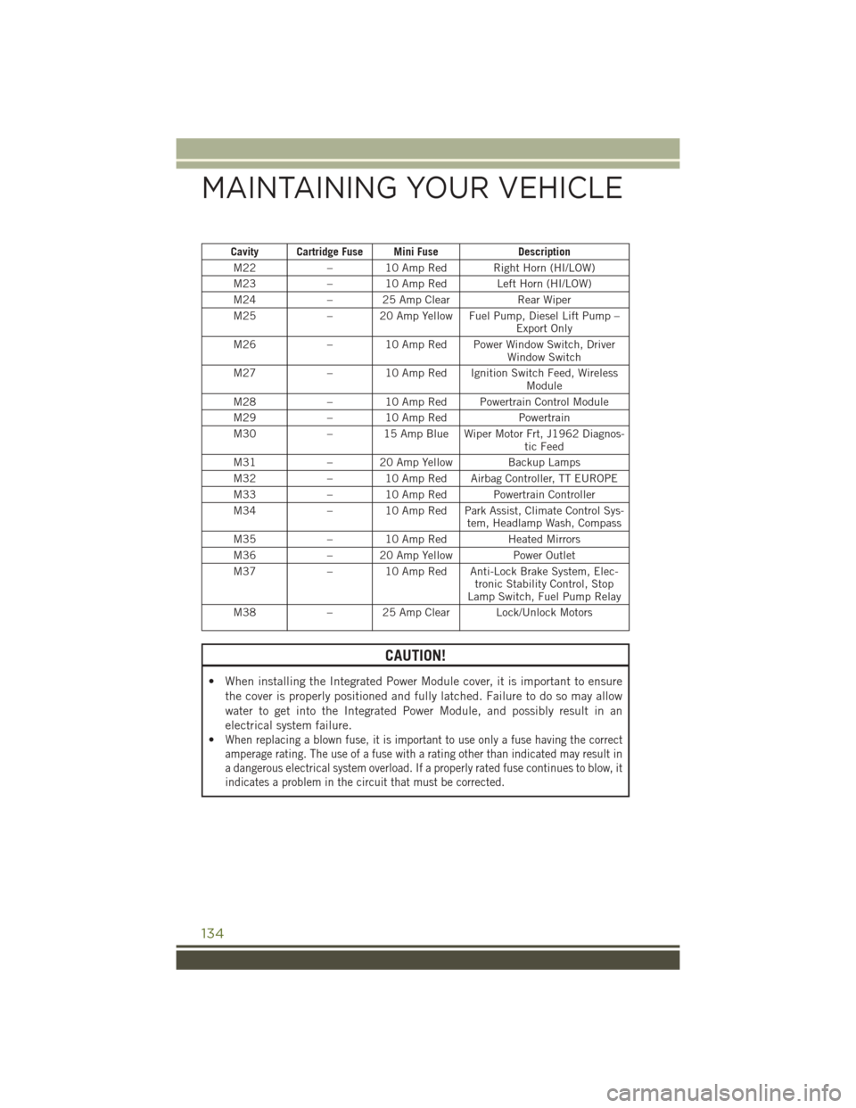
Cavity Cartridge Fuse Mini FuseDescription
M22 – 10 Amp Red Right Horn (HI/LOW)
M23 – 10 Amp Red Left Horn (HI/LOW)
M24 – 25 Amp Clear Rear Wiper
M25 – 20 Amp Yellow Fuel Pump, Diesel Lift Pump –
Export Only
M26 – 10 Amp Red Power Window Switch, Driver
Window Switch
M27 – 10 Amp Red Ignition Switch Feed, Wireless
Module
M28 – 10 Amp Red Powertrain Control Module
M29 – 10 Amp Red Powertrain
M30 – 15 Amp Blue Wiper Motor Frt, J1962 Diagnos-
tic Feed
M31 – 20 Amp Yellow Backup Lamps
M32 – 10 Amp Red Airbag Controller, TT EUROPE
M33 – 10 Amp Red Powertrain Controller
M34 – 10 Amp Red Park Assist, Climate Control Sys-
tem, Headlamp Wash, Compass
M35 – 10 Amp Red Heated Mirrors
M36 – 20 Amp Yellow Power Outlet
M37 – 10 Amp Red Anti-Lock Brake System, Elec-
tronic Stability Control, Stop
Lamp Switch, Fuel Pump Relay
M38 – 25 Amp Clear Lock/Unlock Motors
CAUTION!
• When installing the Integrated Power Module cover, it is important to ensure
the cover is properly positioned and fully latched. Failure to do so may allow
water to get into the Integrated Power Module, and possibly result in an
electrical system failure.
•
When replacing a blown fuse, it is important to use only a fuse having the correct
amperage rating. The use of a fuse with a rating other than indicated may result in
a dangerous electrical system overload. If a properly rated fuse continues to blow, it
indicates a problem in the circuit that must be corrected.
MAINTAINING YOUR VEHICLE
134
Page 137 of 156
TIRES — GENERAL INFORMATION
TIRE PRESSURES
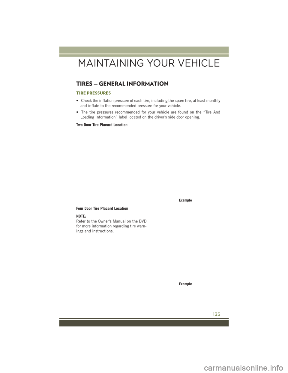
• Check the inflation pressure of each tire, including the spare tire, at least monthlyand inflate to the recommended pressure for your vehicle.
• The tire pressures recommended for your vehicle are found on the “Tire And Loading Information” label located on the driver’s side door opening.
Two Door Tire Placard Location
Four Door Tire Placard Location
NOTE:
Refer to the Owner's Manual on the DVD
for more information regarding tire warn-
ings and instructions.
Example
Example
MAINTAINING YOUR VEHICLE
135
Page 138 of 156
WARNING!
• Overloading of your tires is dangerous. Overloading can cause tire failure,affect vehicle handling, and increase your stopping distance. Use tires of the
recommended load capacity for your vehicle. Never overload them.
•
Improperly inflated tires are dangerous and can cause collisions. Under-inflation is
the leading cause of tire failure and may result in severe cracking, component
separation, or “blow out”. Over-inflation reduces a tire’s ability to cushion shock.
Objects on the road and chuck holes can cause damage that results in tire failure.
Unequal tire pressures can cause steering problems. You could lose control of your
vehicle. Over-inflated or under-inflated tires can affect vehicle handling and can fail
suddenly, resulting in loss of vehicle control.
SPARE TIRES — IF EQUIPPED
NOTE:
For vehicles equipped with Tire Service Kit instead of a spare tire, please refer to “Tire
Service Kit” in “What To Do In Emergencies” on your DVD for further information.
CAUTION!
Because of the reduced ground clearance, do not take your vehicle through an
automatic car wash with a compact or limited-use temporary spare installed.
Damage to the vehicle may result.
Spare Tire Matching Original Equipped Tire And Wheel — If Equipped
Your vehicle may be equipped with a spare tire and wheel equivalent in look and function
to the original equipment tire and wheel found on the front or rear axle of your vehicle. This
spare tire may be used in the tire rotation for your vehicle. If your vehicle has this option,
refer to an authorized tire dealer for the recommended tire rotation pattern.
Compact Spare Tire — If Equipped
The compact spare is for temporary emergency use only. You can identify if your
vehicle is equipped with a compact spare by looking at the spare tire description on
the Tire and Loading Information Placard located on the driver’s side door opening or
on the sidewall of the tire. Compact spare tire descriptions begin with the letter “T”
or “S” preceding the size designation. Example: T145/80D18 103M.
T,S=T emporary Spare Tire
Since this tire has limited tread life, the original equipment tire should be repaired
(or replaced) and reinstalled on your vehicle at the first opportunity.
Do not install a wheel cover or attempt to mount a conventional tire on the compact spare
wheel, since the wheel is designed specifically for the compact spare tire. Do not install
more than one compact spare tire and wheel on the vehicle at any given time.
MAINTAINING YOUR VEHICLE
136
Page 139 of 156
WARNING!
Compact spares are for temporary emergency use only. With these spares, do not
drive more than 50 mph (80 km/h). Temporary use spares have limited tread life.
When the tread is worn to the tread wear indicators, the temporary use spare tire
needs to be replaced. Be sure to follow the warnings, which apply to your spare.
Failure to do so could result in spare tire failure and loss of vehicle control.
Full Size Spare — If Equipped
The full size spare is for temporary emergency use only. This tire may look like the
originally equipped tire on the front or rear axle of your vehicle, but it is not. This
spare tire may have limited tread life. When the tread is worn to the tread wear
indicators, the temporary use full size spare tire needs to be replaced. Since it is not
the same as your original equipment tire, replace (or repair) the original equipment
tire and reinstall on the vehicle at the first opportunity.
Limited-Use Spare — If Equipped
The limited-use spare tire is for temporary emergency use only. This tire is identified
by a label located on the limited-use spare wheel. This label contains the driving
limitations for this spare. This tire may look like the original equipped tire on the front
or rear axle of your vehicle, but it is not. Installation of this limited-use spare tire
affects vehicle handling. Since it is not the same as your original equipment tire,
replace (or repair) the original equipment tire and reinstall on the vehicle at the first
opportunity.
WARNING!
Limited-use spares are for emergency use only. Installation of this limited-use
spare tire affects vehicle handling. With this tire, do not drive more than the speed
listed on the limit-use spare wheel. Keep inflated to the cold tire inflation
pressures listed on your Tire and Loading Information Placard located on the
driver’s side B-Pillar or the rear edge of the driver’s side door. Replace (or repair)
the original equipment tire at the first opportunity and reinstall it on your vehicle.
Failure to do so could result in loss of vehicle control.
MAINTAINING YOUR VEHICLE
137
Page 140 of 156
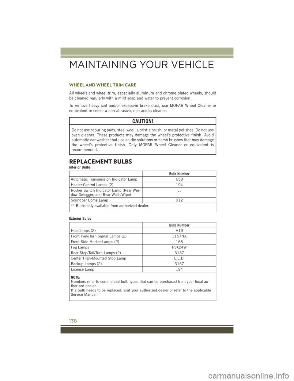
WHEEL AND WHEEL TRIM CARE
All wheels and wheel trim, especially aluminum and chrome plated wheels, should
be cleaned regularly with a mild soap and water to prevent corrosion.
To remove heavy soil and/or excessive brake dust, use MOPAR Wheel Cleaner or
equivalent or select a non-abrasive, non-acidic cleaner.
CAUTION!
Do not use scouring pads, steel wool, a bristle brush, or metal polishes. Do not use
oven cleaner. These products may damage the wheel's protective finish. Avoid
automatic car washes that use acidic solutions or harsh brushes that may damage
the wheel's protective finish. Only MOPAR Wheel Cleaner or equivalent is
recommended.
REPLACEMENT BULBS
Interior Bulbs
Bulb Number
Automatic Transmission Indicator Lamp 658
Heater Control Lamps (2) 194
Rocker Switch Indicator Lamp (Rear Win-
dow Defogger, and Rear Wash/Wipe) **
Soundbar Dome Lamp 912
** Bulbs only available from authorized dealer.
Exterior Bulbs
Bulb Number
Headlamps (2) H13
Front Park/Turn Signal Lamps (2) 3157NA
Front Side Marker Lamps (2) 168
Fog Lamps PSX24W
Rear Stop/Tail/Turn Lamps (2) 3157
Center High-Mounted Stop Lamp L.E.D.
Backup Lamps (2) 3157
License Lamp 194
NOTE:
Numbers refer to commercial bulb types that can be purchased from your local au-
thorized dealer.
If a bulb needs to be replaced, visit your authorized dealer or refer to the applicable
Service Manual.
MAINTAINING YOUR VEHICLE
138