light JEEP WRANGLER 2016 JK / 3.G Owner's Manual
[x] Cancel search | Manufacturer: JEEP, Model Year: 2016, Model line: WRANGLER, Model: JEEP WRANGLER 2016 JK / 3.GPages: 156, PDF Size: 8.82 MB
Page 29 of 156
HEATED SEATS
On some models, the front driver and passenger seats may be equipped with heaters
in both the seat cushions and seatbacks.
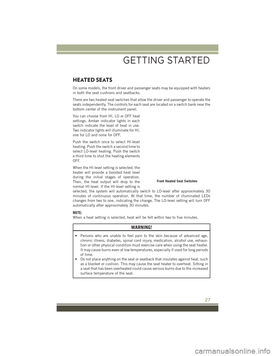
There are two heated seat switches that allow the driver and passenger to operate the
seats independently. The controls for each seat are located on a switch bank near the
bottom center of the instrument panel.
You can choose from HI, LO or OFF heat
settings. Amber indicator lights in each
switch indicate the level of heat in use.
Two indicator lights will illuminate for HI,
one for LO and none for OFF.
Push the switch once to select HI-level
heating. Push the switch a second time to
select LO-level heating. Push the switch
a third time to shut the heating elements
OFF.
When the HI-level setting is selected, the
heater will provide a boosted heat level
during the initial stages of operation.
Then, the heat output will drop to the
normal HI-level. If the HI-level setting is
selected, the system will automatically switch to LO-level after approximately 30
minutes of continuous operation. At that time, the number of illuminated LEDs
changes from two to one, indicating the change. The LO-level setting will turn OFF
automatically after approximately 30 minutes.
NOTE:
When a heat setting is selected, heat will be felt within two to five minutes.
WARNING!
• Persons who are unable to feel pain to the skin because of advanced age,chronic illness, diabetes, spinal cord injury, medication, alcohol use, exhaus-
tion or other physical condition must exercise care when using the seat heater.
It may cause burns even at low temperatures, especially if used for long periods
of time.
• Do not place anything on the seat or seatback that insulates against heat, such
as a blanket or cushion. This may cause the seat heater to overheat. Sitting in
a seat that has been overheated could cause serious burns due to the increased
surface temperature of the seat.
Front Heated Seat Switches
GETTING STARTED
27
Page 30 of 156
ENGINE BREAK-IN RECOMMENDATIONS
A long break-in period is not required for the engine and drivetrain (transmission and
axle) in your vehicle.
Drive moderately during the first 300 miles (500 km). After the initial 60 miles
(100 km), speeds up to 50 or 55 mph (80 or 90 km/h) are desirable.
While cruising, brief full-throttle acceleration within the limits of local traffic laws
contributes to a good break-in. Wide-open throttle acceleration in low gear can be
detrimental and should be avoided.
The engine oil installed in the engine at the factory is a high-quality energy
conserving type lubricant. Oil changes should be consistent with anticipated climate
conditions under which vehicle operations will occur. Refer to “Maintaining Your
Vehicle,” for the recommended viscosity and quality grades.
NOTE:
A new engine may consume some oil during its first few thousand miles (kilometers)
of operation. This should be considered a normal part of the break-in and not
interpreted as an indication of an engine problem or malfunction.
CAUTION!
Never use Non-Detergent Oil or Straight Mineral Oil in the engine or damage may
result.
TURN SIGNAL/LIGHTS LEVER
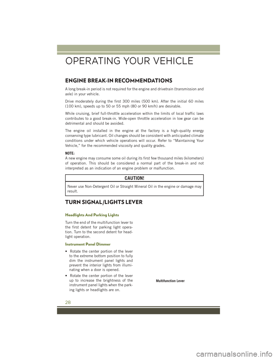
Headlights And Parking Lights
Turn the end of the multifunction lever to
the first detent for parking light opera-
tion. Turn to the second detent for head-
light operation.
Instrument Panel Dimmer
• Rotate the center portion of the leverto the extreme bottom position to fully
dim the instrument panel lights and
prevent the interior lights from illumi-
nating when a door is opened.
• Rotate the center portion of the lever up to increase the brightness of the
instrument panel lights when the park-
ing lights or headlights are on.
Multifunction Lever
OPERATING YOUR VEHICLE
28
Page 31 of 156
• Rotate the center portion of the lever upward to the next detent position tobrighten the odometer and radio controls when the parking lights or headlights are
on.
• Rotate the center portion of the lever upward to the last detent to turn on the interior lighting.
Flash-To-Pass
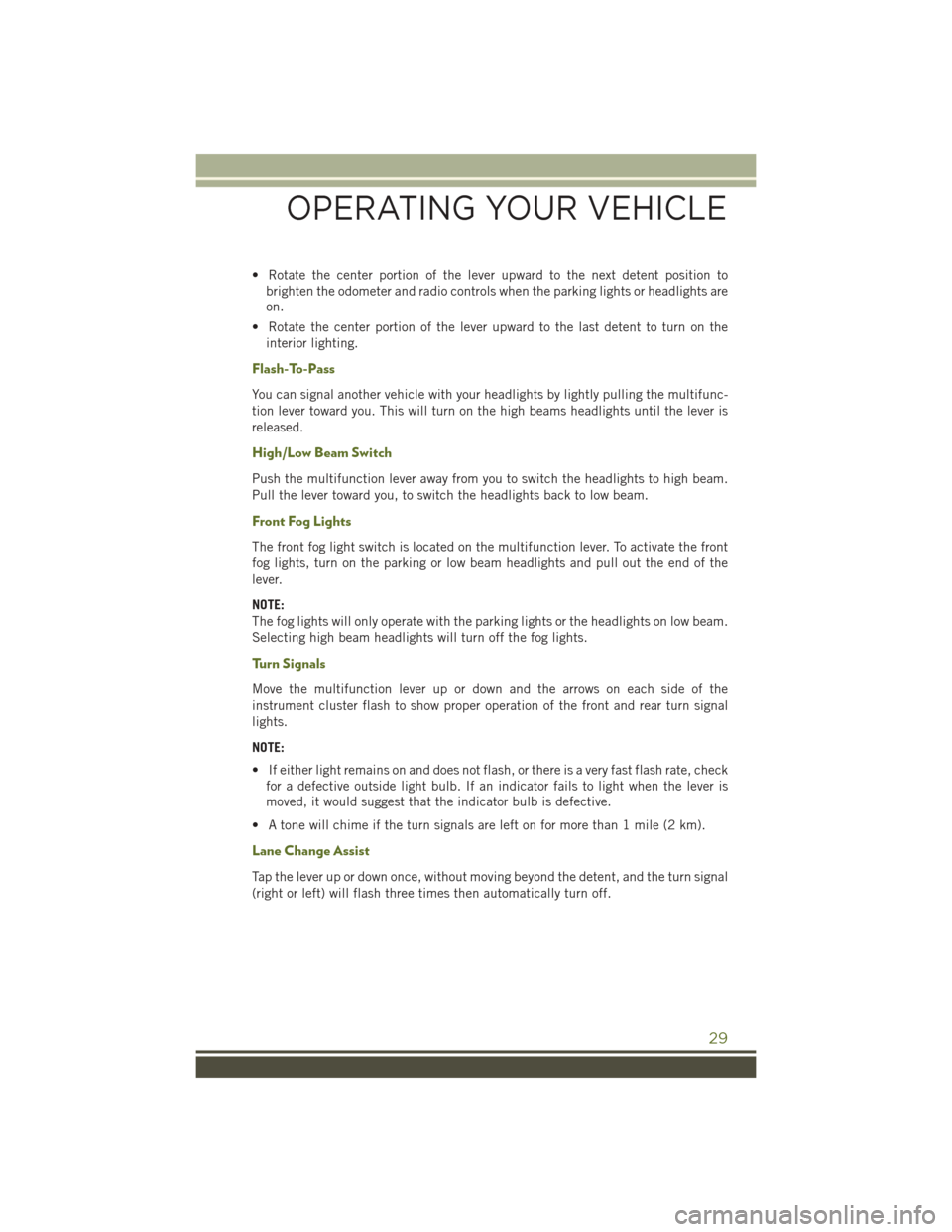
You can signal another vehicle with your headlights by lightly pulling the multifunc-
tion lever toward you. This will turn on the high beams headlights until the lever is
released.
High/Low Beam Switch
Push the multifunction lever away from you to switch the headlights to high beam.
Pull the lever toward you, to switch the headlights back to low beam.
Front Fog Lights
The front fog light switch is located on the multifunction lever. To activate the front
fog lights, turn on the parking or low beam headlights and pull out the end of the
lever.
NOTE:
The fog lights will only operate with the parking lights or the headlights on low beam.
Selecting high beam headlights will turn off the fog lights.
Turn Signals
Move the multifunction lever up or down and the arrows on each side of the
instrument cluster flash to show proper operation of the front and rear turn signal
lights.
NOTE:
• If either light remains on and does not flash, or there is a very fast flash rate, checkfor a defective outside light bulb. If an indicator fails to light when the lever is
moved, it would suggest that the indicator bulb is defective.
• A tone will chime if the turn signals are left on for more than 1 mile (2 km).
Lane Change Assist
Tap the lever up or down once, without moving beyond the detent, and the turn signal
(right or left) will flash three times then automatically turn off.
OPERATING YOUR VEHICLE
29
Page 34 of 156
ELECTRONIC SPEED CONTROL
When engaged, the Electronic Speed Control takes over accelerator operations at
speeds greater than 25 mph (40 km/h).
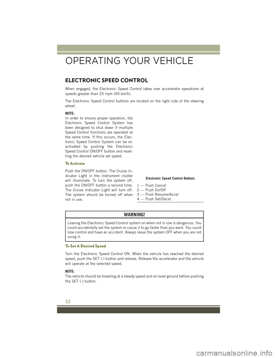
The Electronic Speed Control buttons are located on the right side of the steering
wheel.
NOTE:
In order to ensure proper operation, the
Electronic Speed Control System has
been designed to shut down if multiple
Speed Control functions are operated at
the same time. If this occurs, the Elec-
tronic Speed Control System can be re-
activated by pushing the Electronic
Speed Control ON/OFF button and reset-
ting the desired vehicle set speed.
To Activate
Push the ON/OFF button. The Cruise In-
dicator Light in the instrument cluster
will illuminate. To turn the system off,
push the ON/OFF button a second time.
The Cruise Indicator Light will turn off.
The system should be turned off when
not in use.
WARNING!
Leaving the Electronic Speed Control system on when not in use is dangerous. You
could accidentally set the system or cause it to go faster than you want. You could
lose control and have an accident. Always leave the system OFF when you are not
using it.
To Set A Desired Speed
Turn the Electronic Speed Control ON. When the vehicle has reached the desired
speed, push the SET (-) button and release. Release the accelerator and the vehicle
will operate at the selected speed.
NOTE:
The vehicle should be traveling at a steady speed and on level ground before pushing
the SET (-) button.
Electronic Speed Control Buttons
1 — Push Cancel
2 — Push On/Off
3 — Push Resume/Accel
4 — Push Set/Decel
OPERATING YOUR VEHICLE
32
Page 36 of 156
To Decrease Speed
When the Electronic Speed Control is set, you can decrease speed by pushing the
SET (-) button.
The drivers preferred units can be selected through the instrument panel settings if
equipped. Refer to “Understanding Your Instrument Panel” in the Owner’s Manual
on the DVD for more information. The speed decrement shown is dependant on the
chosen speed unit of U.S. (mph) or Metric (km/h):
U.S. Speed (mph)
• Pushing the SET (-) button once will result in a 1 mph decrease in set speed. Eachsubsequent tap of the button results in a decrease of 1 mph.
• If the button is continually pushed, the set speed will continue to decrease until the button is released, then the new set speed will be established.
Metric Speed (km/h)
• Pushing the SET (-) button once will result in a 1 km/h decrease in set speed. Each subsequent tap of the button results in a decrease of 1 km/h.
• If the button is continually pushed, the set speed will continue to decrease until the button is released, then the new set speed will be established.
To Accelerate For Passing
Press the accelerator as you would normally. When the pedal is released, the vehicle
will return to the set speed.
Using Electronic Speed Control On Hills
The transmission may downshift on hills to maintain the vehicle set speed.
NOTE:
The Electronic Speed Control system maintains speed up and down hills. A slight
speed change on moderate hills is normal.
On steep hills, a greater speed loss or gain may occur so it may be preferable to drive
without Electronic Speed Control.
WARNING!
Electronic Speed Control can be dangerous where the system cannot maintain a
constant speed. Your vehicle could go too fast for the conditions, and you could
lose control and have an accident. Do not use Electronic Speed Control in heavy
traffic or on roads that are winding, icy, snow-covered or slippery.
OPERATING YOUR VEHICLE
34
Page 38 of 156
AUTOMATIC TEMPERATURE CONTROLS (ATC)
Automatic Operation
• Turn the Mode and Blower Controls to the AUTO position.
• Select the desired temperature by rotating the Temperature Control.
• The system will maintain the set temperature automatically.
Air Conditioning (A/C)
• If the air conditioning button is pushed while in AUTO mode, the indicator lightwill flash three times to indicate the cabin air is being controlled automatically.
Air Recirculation
• Use Recirculation for maximum A/C operation.
• For window defogging, turn the Recirculation button off.
• If the Recirculation button is pushed while in the AUTO mode, the indicator lightmay flash three times to indicate the cabin air is being controlled automatically.
Heated Mirrors
The mirrors are heated to melt frost or ice. This feature is activated whenever you turn
on the rear window defroster.
Automatic Temperature Controls
1 — Rotate Blower Control 4 — Push A/C Button
2 — Push Air Recirculation Button 5 — Rotate Mode Control
3 — Rotate Temperature Control 6 — Push Rear Window Defroster But- ton
OPERATING YOUR VEHICLE
36
Page 90 of 156
PROGRAMMABLE FEATURES
Electronic Vehicle Information Center (EVIC)
The EVIC can be used to program the following Personal Settings. Push theMENU
button until Personal Settings displays, then push the DOWNarrow button
to
scroll through the settings. Push the RIGHTarrow button
to change the setting.
• Language • Illumin Approach
• Auto UNLK On Exit • Hill Start Assist (HSA)
• RKE Unlock • Display Units of Measure In
• Sound Horn With RKE Lock • Nav – Turn by Turn
• Flash Lamp With Lock • Display Fuel Saver
• Headlamp Off Delay • Compass Variance
• Headlamps With Wipers • Calibrate Compass
• Key-Off Power Delay
Key Fob Programmable Features
The following features may also be programmed by using the Key Fob transmitter or
the ignition and driver's door lock switch. Refer to “Uconnect Settings” in “Under-
standing Your Instrument Panel” in the Owner’s Manual on the DVD for further
information.
NOTE:
Pushing the LOCK button while you are inside the vehicle will activate the Vehicle
Security Alarm. Opening a door with the Vehicle Security Alarm activated will cause
the alarm to sound. Push the UNLOCK button to deactivate the Vehicle Security
Alarm.
Flashing Lamps With Lock
The turn signal lights flashing, when the doors are locked or unlocked, feature can be
turned on or off. To turn this feature on or off:
• Push and hold the UNLOCK button for at least 4 seconds, but no longer than 10 seconds. Then, push and hold the LOCK button while still holding the UNLOCK
button.
• Release both buttons at the same time.
ELECTRONICS
88
Page 91 of 156
POWER INVERTER
• A 115 Volt, 150 Watt AC power in-verter is located on the front of the
center console.
• This outlet can power cellular phones, electronics and other low power de-
vices requiring power up to 150 Watts.
• The power inverter switch is located on the instrument panel below the cli-
mate controls. To turn on the power
outlet, push the switch once. The indi-
cator light will illuminate. Push the
switch a second time to turn the power
inverter outlet off.
NOTE:
The power inverter is designed with
built-in overload protection. If the power rating of 150 Watts is exceeded, the power
inverter will automatically shut down. Once the electrical device has been removed
from the outlet, the inverter should automatically reset. If the power rating exceeds
approximately 170 Watts, the power inverter may have to be reset manually. To reset
the inverter manually, unplug the device and plug it in again. To avoid overloading the
circuit, check the power ratings on electrical devices prior to using the inverter.
WARNING!
To Avoid Serious Injury or Death DO NOT:
• insert any objects into the receptacles
• touch with wet hands
Close the lid when not in use. If this outlet is mishandled, it may cause an electric
shock and failure.
Power Inverter
ELECTRONICS
89
Page 92 of 156
POWER OUTLETS
There are three possible 12 Volt Power Outlets in this vehicle.
• The front 12 Volt power outlet is located below the climate controls in the CenterConsole, and is powered when the ignition switch is in the ON/RUN position. The
outlet can operate a conventional cigar lighter unit or power accessories designed
for use with a standard power outlet adapter.
• The center console 12 Volt power outlet is powered directly from the battery (power available at all times). Items plugged into this outlet may discharge the
battery and/or prevent the engine from starting.
Power Outlet — Front
Power Outlet — Center Console
ELECTRONICS
90
Page 93 of 156
• On vehicles equipped with a rear subwoofer, there is also a 12 Volt power outletlocated in the rear cargo area of the vehicle. This power outlet has power available
directly from the battery (power available at all times). Items plugged into this
outlet also may discharge the battery and/or prevent the engine from starting.
NOTE: •
Do not exceed the maximum power of160 Watts (13 Amps) at 12 Volts. If
the 160 Watt (13 Amp) power rating is
exceeded the fuse protecting the sys-
tem will need to be replaced.
• Power outlets are designed for ac-
cessory plugs only. Do not insert any
other object in the power outlet as
this will damage the outlet and blow
the fuse. Improper use of the power
outlet can cause damage not cov-
ered by your new vehicle warranty.
Power Outlet — Rear Cargo Area
Power Outlet Fuses
1 — #M7 Fuse 20 Amp Yellow – Power Outlet Rear (If Equipped)
2 — #M6 Fuse 20 Amp Yellow – Cigar Lighter Instrument Panel
3 — #M36 Fuse 20 Amp Yellow – Power Outlet Console Bin
ELECTRONICS
91