service JEEP WRANGLER 2016 JK / 3.G Owner's Manual
[x] Cancel search | Manufacturer: JEEP, Model Year: 2016, Model line: WRANGLER, Model: JEEP WRANGLER 2016 JK / 3.GPages: 156, PDF Size: 8.82 MB
Page 109 of 156
CRUISE- Cruise Set Indicator
Indicates that the cruise control has been set.
IF YOUR ENGINE OVERHEATS
In any of the following situations, you can reduce the potential for overheating by
taking the appropriate action.
• On the highways — slow down.
• In city traffic — while stopped, shift transmission into NEUTRAL, but do notincrease engine idle speed.
CAUTION!
Driving with a hot cooling system could damage your vehicle. If the temperature
gauge reads HOT (H), pull over and stop the vehicle. Idle the vehicle with the air
conditioner turned off until the pointer drops back into the normal range. If the
pointer remains on HOT (H), and you hear continuous chimes, turn the engine off
immediately, and call for service.
NOTE:
There are steps that you can take to slow down an impending overheat condition:
• If your air conditioner (A/C) is on, turn it off. The A/C system adds heat to the engine cooling system and turning the A/C off can help remove this heat.
• You can also turn the temperature control to maximum heat, the mode control to floor and the blower control to high. This allows the heater core to act as a
supplement to the radiator and aids in removing heat from the engine cooling
system.
WARNING!
You or others can be badly burned by hot engine coolant (antifreeze) or steam from
your radiator. If you see or hear steam coming from under the hood, do not open
the hood until the radiator has had time to cool. Never try to open a cooling system
pressure cap when the radiator or coolant bottle is hot.
WHAT TO DO IN EMERGENCIES
107
Page 110 of 156
JACKING AND TIRE CHANGING
WARNING!
• Do not attempt to change a tire on the side of the vehicle close to movingtraffic. Pull far enough off the road to avoid the danger of being hit when
operating the jack or changing the wheel.
• Being under a jacked-up vehicle is dangerous. The vehicle could slip off the
jack and fall on you. You could be crushed. Never put any part of your body
under a vehicle that is on a jack. If you need to get under a raised vehicle, take
it to a service center where it can be raised on a lift.
• Never start or run the engine while the vehicle is on a jack.
• The jack is designed to be used as a tool for changing tires only. The jack
should not be used to lift the vehicle for service purposes. The vehicle should
be jacked on a firm level surface only. Avoid ice or slippery areas.
Jack Location
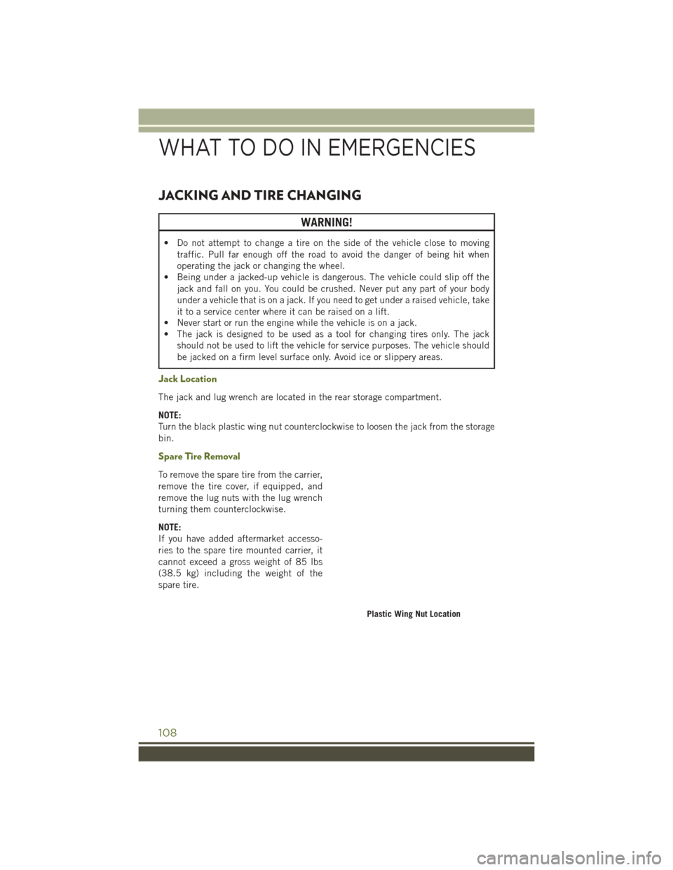
The jack and lug wrench are located in the rear storage compartment.
NOTE:
Turn the black plastic wing nut counterclockwise to loosen the jack from the storage
bin.
Spare Tire Removal
To remove the spare tire from the carrier,
remove the tire cover, if equipped, and
remove the lug nuts with the lug wrench
turning them counterclockwise.
NOTE:
If you have added aftermarket accesso-
ries to the spare tire mounted carrier, it
cannot exceed a gross weight of 85 lbs
(38.5 kg) including the weight of the
spare tire.
Plastic Wing Nut Location
WHAT TO DO IN EMERGENCIES
108
Page 112 of 156
Jacking Instructions
WARNING!
Carefully follow these tire changing warnings to help prevent personal injury or
damage to your vehicle:
• Always park on a firm, level surface as far from the edge of the roadway aspossible before raising the vehicle.
• Turn on the Hazard Warning flasher.
• Block the wheel diagonally opposite the wheel to be raised.
• Set the parking brake firmly and set an automatic transmission in PARK; a
manual transmission in REVERSE.
• Never start or run the engine with the vehicle on a jack.
• Do not let anyone sit in the vehicle when it is on a jack.
• Do not get under the vehicle when it is on a jack. If you need to get under a
raised vehicle, take it to a service center where it can be raised on a lift.
• Only use the jack in the positions indicated and for lifting this vehicle during
a tire change.
• If working on or near a roadway, be extremely careful of motor traffic.
• To assure that spare tires, flat or inflated, are securely stowed, spares must be
stowed with the valve stem facing the ground.
CAUTION!
Do not attempt to raise the vehicle by jacking on locations other than those
indicated in the Jacking Instructions for this vehicle.
1. Remove the spare tire, jack and tools from the stored location.
2. Loosen (but do not remove) the wheel lug nuts by turning them to the left one turn while the wheel is still on the ground.
3. Assemble the jack and jacking tools. Connect the jack handle driver to the extension, then to the lug wrench.
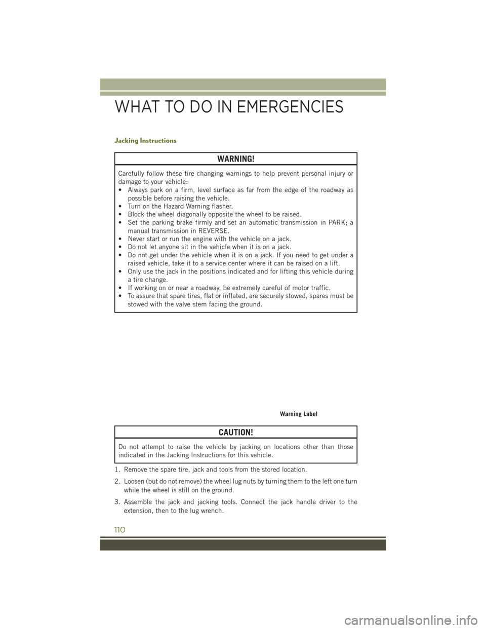
Warning Label
WHAT TO DO IN EMERGENCIES
110
Page 114 of 156
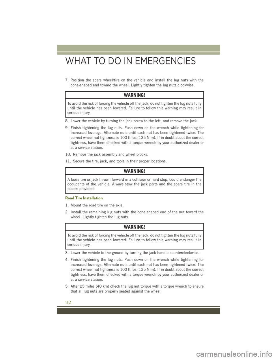
7. Position the spare wheel/tire on the vehicle and install the lug nuts with thecone-shaped end toward the wheel. Lightly tighten the lug nuts clockwise.
WARNING!
To avoid the risk of forcing the vehicle off the jack, do not tighten the lug nuts fully
until the vehicle has been lowered. Failure to follow this warning may result in
serious injury.
8. Lower the vehicle by turning the jack screw to the left, and remove the jack.
9. Finish tightening the lug nuts. Push down on the wrench while tightening for increased leverage. Alternate nuts until each nut has been tightened twice. The
correct wheel nut tightness is 100 ft lbs (135 N·m). If in doubt about the correct
tightness, have them checked with a torque wrench by your authorized dealer or
at a service station.
10. Remove the jack assembly and wheel blocks.
11. Secure the tire, jack, and tools in their proper locations.
WARNING!
A loose tire or jack thrown forward in a collision or hard stop, could endanger the
occupants of the vehicle. Always stow the jack parts and the spare tire in the
places provided.
Road Tire Installation
1. Mount the road tire on the axle.
2. Install the remaining lug nuts with the cone shaped end of the nut toward the wheel. Lightly tighten the lug nuts.
WARNING!
To avoid the risk of forcing the vehicle off the jack, do not tighten the lug nuts fully
until the vehicle has been lowered. Failure to follow this warning may result in
serious injury.
3. Lower the vehicle to the ground by turning the jack handle counterclockwise.
4. Finish tightening the lug nuts. Push down on the wrench while tightening for increased leverage. Alternate nuts until each nut has been tightened twice. The
correct wheel nut tightness is 100 ft lbs (135 N·m). If in doubt about the correct
tightness, have them checked with a torque wrench by your authorized dealer or
at a service station.
5. After 25 miles (40 km) check the lug nut torque with a torque wrench to ensure that all lug nuts are properly seated against the wheel.
WHAT TO DO IN EMERGENCIES
112
Page 119 of 156
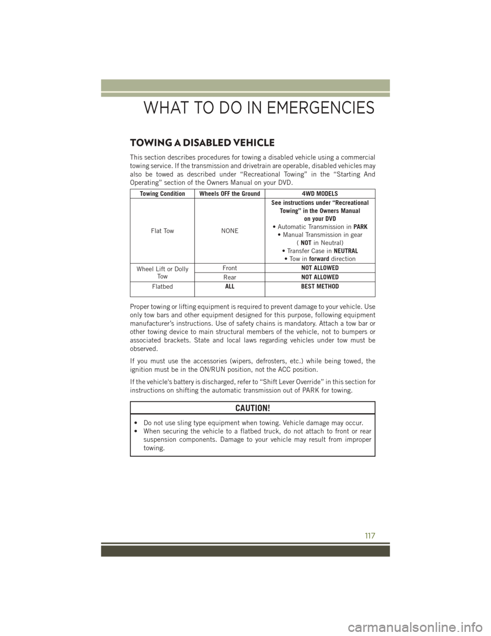
TOWING A DISABLED VEHICLE
This section describes procedures for towing a disabled vehicle using a commercial
towing service. If the transmission and drivetrain are operable, disabled vehicles may
also be towed as described under “Recreational Towing” in the “Starting And
Operating” section of the Owners Manual on your DVD.
Towing Condition Wheels OFF the Ground4WD MODELS
Flat Tow NONESee instructions under “Recreational
Towing” in the Owners Manual on your DVD
• Automatic Transmission in PARK
• Manual Transmission in gear (NOT in Neutral)
• Transfer Case in NEUTRAL
• Tow in forwarddirection
Wheel Lift or Dolly To w Front
NOT ALLOWED
Rear NOT ALLOWED
Flatbed ALL
BEST METHOD
Proper towing or lifting equipment is required to prevent damage to your vehicle. Use
only tow bars and other equipment designed for this purpose, following equipment
manufacturer’s instructions. Use of safety chains is mandatory. Attach a tow bar or
other towing device to main structural members of the vehicle, not to bumpers or
associated brackets. State and local laws regarding vehicles under tow must be
observed.
If you must use the accessories (wipers, defrosters, etc.) while being towed, the
ignition must be in the ON/RUN position, not the ACC position.
If the vehicle's battery is discharged, refer to “Shift Lever Override” in this section for
instructions on shifting the automatic transmission out of PARK for towing.
CAUTION!
• Do not use sling type equipment when towing. Vehicle damage may occur.
• When securing the vehicle to a flatbed truck, do not attach to front or rear
suspension components. Damage to your vehicle may result from improper
towing.
WHAT TO DO IN EMERGENCIES
117
Page 128 of 156
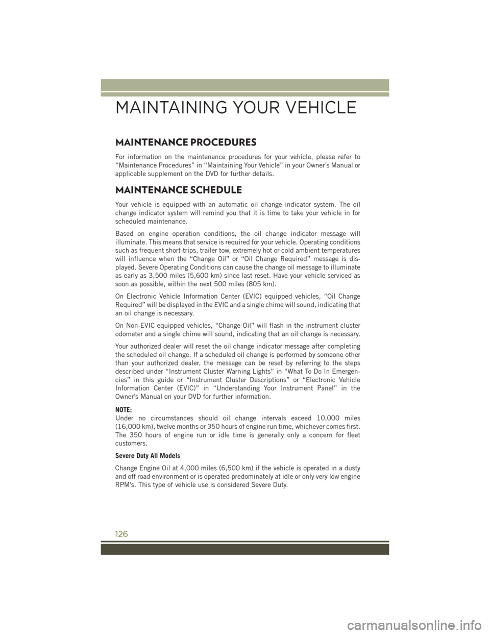
MAINTENANCE PROCEDURES
For information on the maintenance procedures for your vehicle, please refer to
“Maintenance Procedures” in “Maintaining Your Vehicle” in your Owner’s Manual or
applicable supplement on the DVD for further details.
MAINTENANCE SCHEDULE
Your vehicle is equipped with an automatic oil change indicator system. The oil
change indicator system will remind you that it is time to take your vehicle in for
scheduled maintenance.
Based on engine operation conditions, the oil change indicator message will
illuminate. This means that service is required for your vehicle. Operating conditions
such as frequent short-trips, trailer tow, extremely hot or cold ambient temperatures
will influence when the “Change Oil” or “Oil Change Required” message is dis-
played. Severe Operating Conditions can cause the change oil message to illuminate
as early as 3,500 miles (5,600 km) since last reset. Have your vehicle serviced as
soon as possible, within the next 500 miles (805 km).
On Electronic Vehicle Information Center (EVIC) equipped vehicles, “Oil Change
Required” will be displayed in the EVIC and a single chime will sound, indicating that
an oil change is necessary.
On Non-EVIC equipped vehicles, “Change Oil” will flash in the instrument cluster
odometer and a single chime will sound, indicating that an oil change is necessary.
Your authorized dealer will reset the oil change indicator message after completing
the scheduled oil change. If a scheduled oil change is performed by someone other
than your authorized dealer, the message can be reset by referring to the steps
described under “Instrument Cluster Warning Lights” in “What To Do In Emergen-
cies” in this guide or “Instrument Cluster Descriptions” or “Electronic Vehicle
Information Center (EVIC)” in “Understanding Your Instrument Panel” in the
Owner’s Manual on your DVD for further information.
NOTE:
Under no circumstances should oil change intervals exceed 10,000 miles
(16,000 km), twelve months or 350 hours of engine run time, whichever comes first.
The 350 hours of engine run or idle time is generally only a concern for fleet
customers.
Severe Duty All Models
Change Engine Oil at 4,000 miles (6,500 km) if the vehicle is operated in a dusty
and off road environment or is operated predominately at idle or only very low engine
RPM’s. This type of vehicle use is considered Severe Duty.
MAINTAINING YOUR VEHICLE
126
Page 131 of 156
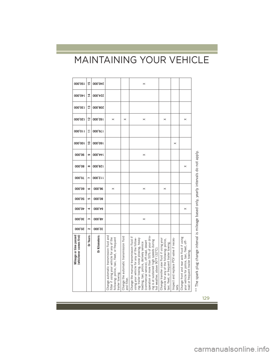
Mileage or time passed
(whichever comes first)
20,000
30,000
40,000
50,000
60,000
70,000
80,000
90,000
100,000
110,000
120,000
130,000
140,000
150,000
Or Years: 2 3 4 5 6 7 8 9 10 11 12 13 14 15
Or Kilometers:
32,000
48,000
64,000
80,000
96,000
112,000
128,000
144,000
160,000
176,000
192,000
208,000
224,000
240,000
Change automatic transmission fluid and
filter if using your vehicle for any of the
following: police, taxi, fleet, or frequent
trailer towing. XX
Change the automatic transmission fluid
and filter. X
Change the manual transmission fluid if
using your vehicle for any of the follow-
ing: trailer towing, snow plowing, heavy
loading, taxi, police, delivery service
(commercial service), off-road, desert
operation or more than 50% of your driv-
ing is at sustained high speeds during
hot weather, above 90°F (32°C). XX X X X
Change transfer case fluid if using your
vehicle for any of the following: police,
taxi, fleet, or frequent trailer towing. XX
Inspect and replace PCV valve if neces-
sary. X
Change front and rear axle fluid if using
your vehicle for police, taxi, fleet, off-
road or frequent trailer towing. XX X** The spark plug change interval is mileage based only, yearly intervals do not apply.
MAINTAINING YOUR VEHICLE
129
Page 132 of 156
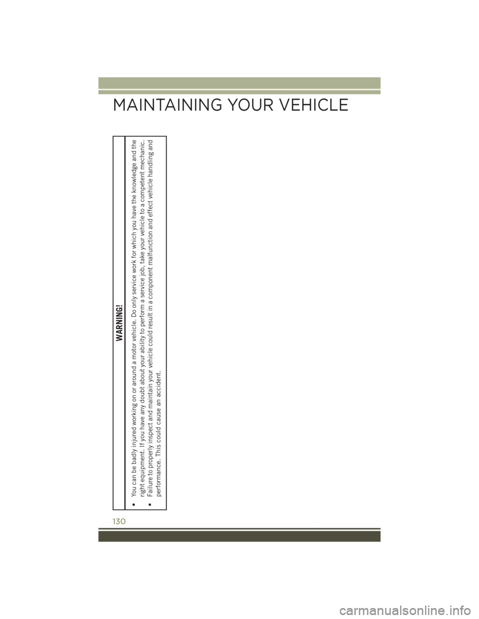
WARNING!
• You can be badly injured working on or around a motor vehicle. Do only service work for which you have the knowledge and theright equipment. If you have any doubt about your ability to perform a service job, take your vehicle to a competent mechanic.
• Failure to properly inspect and maintain your vehicle could result in a component malfunction and effect vehicle handling and
performance. This could cause an accident.
MAINTAINING YOUR VEHICLE
130
Page 133 of 156

MAINTENANCE RECORD
Odometer Date Signature, Autho-rized Service Center
20,000 Miles
(32,000 km) or
2 Years
30,000 Miles
(48,000 km) or
3 Years
40,000 Miles
(64,000 km) or
4 Years
50,000 Miles
(80,000 km) or
5 Years
60,000 Miles
(96,000 km) or
6 Years
70,000 Miles
(112,000 km) or
7 Years
80,000 Miles
(128,000 km) or
8 Years
Odometer Date Signature, Autho- rized Service Center
90,000 Miles
(144,000 km) or
9 Years
100,000 Miles
(160,000 km) or
10 Years
110,000 Miles
(176,000 km) or
11 Years
120,000 Miles
(192,000 km) or
12 Years
130,000 Miles
(208,000 km) or
13 Years
140,000 Miles
(224,000 km) or
14 Years
150,000 Miles
(240,000 km) or
15 Years
MAINTAINING YOUR VEHICLE
131
Page 134 of 156
FUSES
WARNING!
• When replacing a blown fuse, always use an appropriate replacement fuse withthe same amp rating as the original fuse. Never replace a fuse with another
fuse of higher amp rating. Never replace a blown fuse with metal wires or any
other material. Failure to use proper fuses may result in serious personal injury,
fire and/or property damage.
• Before replacing a fuse, make sure that the ignition is off and that all the other
services are switched off and/or disengaged.
• If the replaced fuse blows again, contact an authorized dealer.
• If a general protection fuse for safety systems (air bag system, braking system),
power unit systems (engine system, gearbox system) or steering system blows,
contact an authorized dealer.
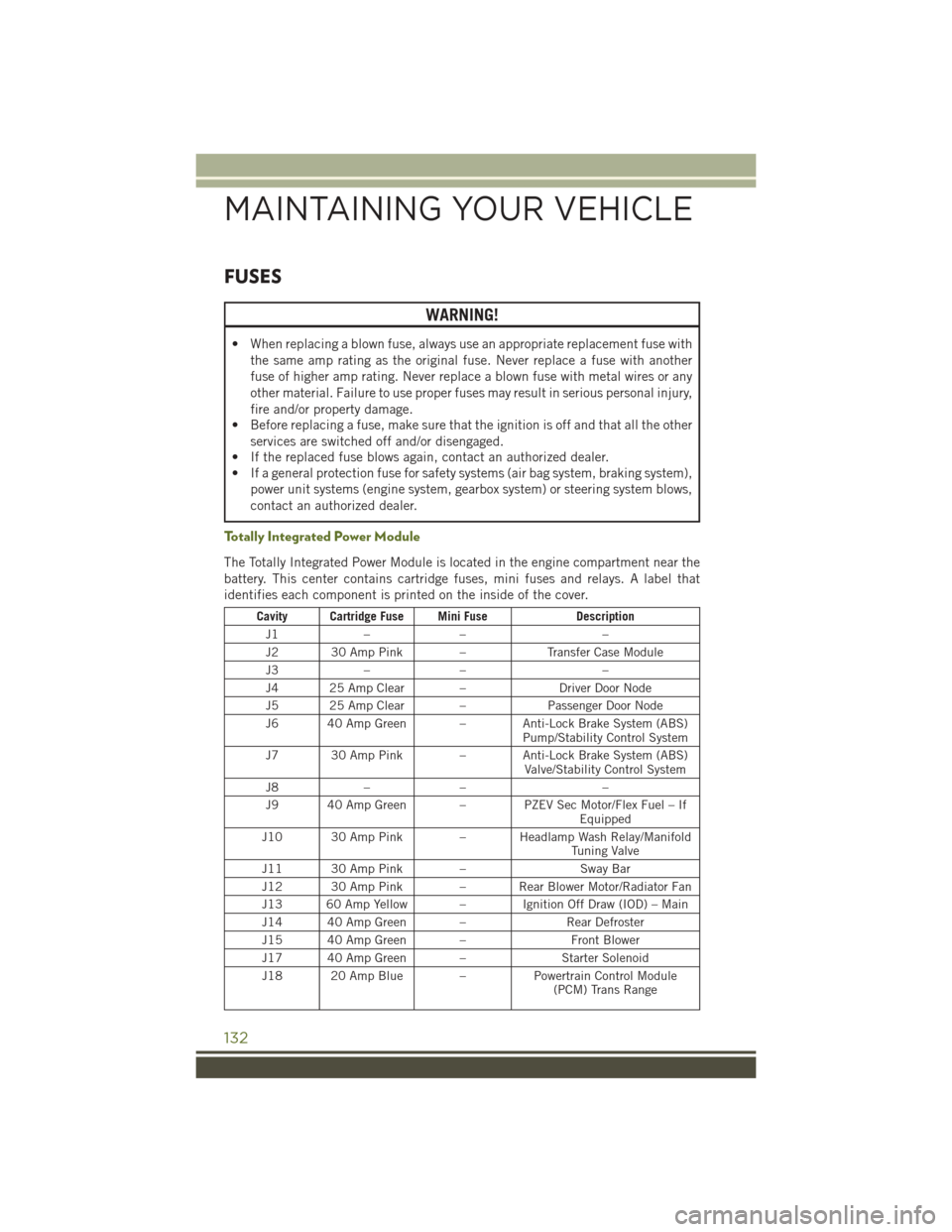
Totally Integrated Power Module
The Totally Integrated Power Module is located in the engine compartment near the
battery. This center contains cartridge fuses, mini fuses and relays. A label that
identifies each component is printed on the inside of the cover.
Cavity Cartridge Fuse Mini Fuse Description
J1 –– –
J2 30 Amp Pink – Transfer Case Module
J3 –– –
J4 25 Amp Clear – Driver Door Node
J5 25 Amp Clear – Passenger Door Node
J6 40 Amp Green – Anti-Lock Brake System (ABS) Pump/Stability Control System
J7 30 Amp Pink – Anti-Lock Brake System (ABS) Valve/Stability Control System
J8 –– –
J9 40 Amp Green – PZEV Sec Motor/Flex Fuel – If Equipped
J10 30 Amp Pink – Headlamp Wash Relay/Manifold Tuning Valve
J11 30 Amp Pink – Sway Bar
J12 30 Amp Pink – Rear Blower Motor/Radiator Fan
J13 60 Amp Yellow – Ignition Off Draw (IOD) – Main
J14 40 Amp Green – Rear Defroster
J15 40 Amp Green – Front Blower
J17 40 Amp Green – Starter Solenoid
J18 20 Amp Blue – Powertrain Control Module
(PCM) Trans Range
MAINTAINING YOUR VEHICLE
132