warning JEEP WRANGLER 2016 JK / 3.G Service Manual
[x] Cancel search | Manufacturer: JEEP, Model Year: 2016, Model line: WRANGLER, Model: JEEP WRANGLER 2016 JK / 3.GPages: 156, PDF Size: 8.82 MB
Page 115 of 156
JUMP-STARTING PROCEDURES
If your vehicle has a discharged battery it can be jump-started using a set of jumper cables
and a battery in another vehicle or by using a portable battery booster pack. Jump-starting
can be dangerous if done improperly so please follow the procedures in this section
carefully.
NOTE:
When using a portable battery booster pack follow the manufacturer’s operating
instructions and precautions.
CAUTION!
Do not use a portable battery booster pack or any other booster source with a
system voltage greater than 12 Volts or damage to the battery, starter motor,
alternator or electrical system may occur.
WARNING!
Do not attempt jump-starting if the battery is frozen. It could rupture or explode
and cause personal injury.
Preparations For Jump-Start
The battery in your vehicle is located in the right rear of the engine compartment,
behind the Power Distribution Center.
Positive Battery Post
WHAT TO DO IN EMERGENCIES
113
Page 116 of 156
WARNING!
•Take care to avoid the radiator cooling fan whenever the hood is raised. It can start
anytime the ignition switch is ON. You can be injured by moving fan blades.
• Remove any metal jewelry such as rings, watch bands and bracelets that couldmake an inadvertent electrical contact. You could be seriously injured.
• Batteries contain sulfuric acid that can burn your skin or eyes and generate
hydrogen gas which is flammable and explosive. Keep open flames or sparks
away from the battery.
1. Set the parking brake, shift the automatic transmission into PARK (manual transmission in NEUTRAL) and turn the ignition to LOCK.
2. Turn off the heater, radio, and all unnecessary electrical accessories.
3. If using another vehicle to jump-start the battery, park the vehicle within the jumper cables reach, set the parking brake and make sure the ignition is OFF.
WARNING!
Do not allow vehicles to touch each other as this could establish a ground
connection and personal injury could result.
Jump Starting Procedure
WARNING!
Failure to follow this jump-starting procedure could result in personal injury or
property damage due to battery explosion.
CAUTION!
Failure to follow these procedures could result in damage to the charging system
of the booster vehicle or the discharged vehicle.
Connecting The Jumper Cables
1. Connect the positive (+)end of the jumper cable to the positive (+)post of the
discharged vehicle.
2. Connect the opposite end of the positive (+)jumper cable to the positive (+)post
of the booster battery.
3. Connect the negative (-)end of the jumper cable to the negative (-)post of the
booster battery.
4. Connect the opposite end of the negative (-)jumper cable to a good engine ground
(exposed metal part of the discharged vehicle’s engine) away from the battery and
the fuel injection system.
WHAT TO DO IN EMERGENCIES
114
Page 117 of 156
WARNING!
Do not connect the jumper cable to the negative (-) post of the discharged battery. The
resulting electrical spark could cause the battery to explode and could result in serious
injury. Only use the specific ground point, do not use any other exposed metal parts.
5. Start the engine in the vehicle that has the booster battery, let the engine idle afew minutes, and then start the engine in the vehicle with the discharged battery.
6. Once the engine is started, remove the jumper cables in the reverse sequence:
Disconnecting The Jumper Cables
1. Disconnect the negative (-)end of the jumper cable from the engine ground of the
vehicle with the discharged battery.
2. Disconnect the opposite end of the negative (-)jumper cable from the negative (-)
post of the booster battery.
3. Disconnect the positive (+)end of the jumper cable from the positive (+)post of
the booster battery.
4. Disconnect the opposite end of the positive (+)jumper cable from the positive (+)
post of the vehicle with the discharged battery.
If frequent jump starting is required to start your vehicle you should have the battery
and charging system inspected at your authorized dealer.
CAUTION!
Accessories plugged into the vehicle power outlets draw power from the vehicle’s
battery, even when not in use (i.e., cellular devices, etc.). Eventually, if plugged in
long enough without engine operation, the vehicle’s battery will discharge suffi-
ciently to degrade battery life and/or prevent the engine from starting.
EMERGENCY TOW HOOKS — IF EQUIPPED
If your vehicle is equipped with tow hooks, they are mounted in the front and the rear.
NOTE:
For off-road recovery, it is recommended to use both of the front tow hooks to minimize the
risk of damage to the vehicle. Always use an appropriately rated tow strap.
WARNING!
• Do not use a chain for freeing a stuck vehicle. Chains may break, causing serious injury or death.
• Stand clear of vehicles when pulling with tow hooks. Tow straps may become
disengaged, causing serious injury.
WHAT TO DO IN EMERGENCIES
115
Page 121 of 156
FREEING A STUCK VEHICLE
If your vehicle becomes stuck in mud, sand or snow, it can often be moved using a
rocking motion. Turn the steering wheel right and left to clear the area around the
front wheels. Then shift back and forth between DRIVE and REVERSE (with
automatic transmission) or 2nd gear and REVERSE (with manual transmission),
while gently pressing the accelerator. Use the least amount of accelerator pedal
pressure that will maintain the rocking motion, without spinning the wheels, or racing
the engine.
CAUTION!
Racing the engine or spinning the wheels may lead to transmission overheating
and failure. Allow the engine to idle with the transmission in NEUTRAL for at least
one minute after every five rocking-motion cycles. This will minimize overheating
and reduce the risk of clutch or transmission failure during prolonged efforts to
free a stuck vehicle.
NOTE:
Push the "ESC Off" switch, to place the Electronic Stability Control (ESC) system in
"Partial Off" mode, before rocking the vehicle. Refer to “Electronic Brake Control” in
“Starting And Operating” in the Owner’s Manual on the DVD for further information.
Once the vehicle has been freed, push the "ESC Off" switch again to restore "ESC On"
mode.
CAUTION!
• When “rocking” a stuck vehicle by shifting between DRIVE/2nd gear and REVERSE, do not spin the wheels faster than 15 mph (24 km/h), or drivetrain
damage may result.
• Revving the engine or spinning the wheels too fast may lead to transmission
overheating and failure. It can also damage the tires. Do not spin the wheels
above 30 mph (48 km/h) while in gear (no transmission shifting occurring).
WARNING!
Fast spinning tires can be dangerous. Forces generated by excessive wheel speeds
may cause damage, or even failure, of the axle and tires. A tire could explode and
injure someone. Do not spin your vehicle's wheels faster than 30 mph (48 km/h)
or for longer than 30 seconds continuously without stopping when you are stuck
and do not let anyone near a spinning wheel, no matter what the speed.
WHAT TO DO IN EMERGENCIES
119
Page 123 of 156
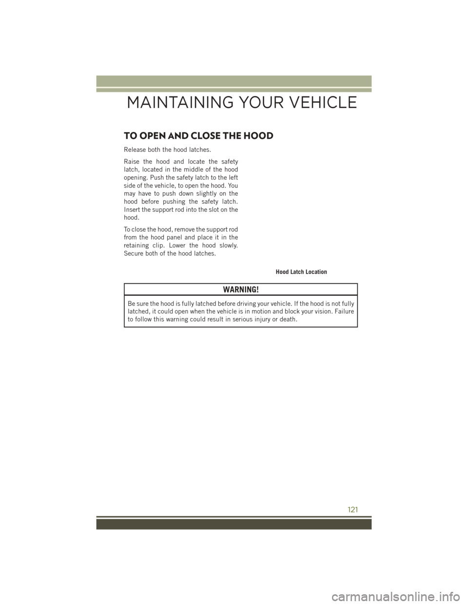
TO OPEN AND CLOSE THE HOOD
Release both the hood latches.
Raise the hood and locate the safety
latch, located in the middle of the hood
opening. Push the safety latch to the left
side of the vehicle, to open the hood. You
may have to push down slightly on the
hood before pushing the safety latch.
Insert the support rod into the slot on the
hood.
To close the hood, remove the support rod
from the hood panel and place it in the
retaining clip. Lower the hood slowly.
Secure both of the hood latches.
WARNING!
Be sure the hood is fully latched before driving your vehicle. If the hood is not fully
latched, it could open when the vehicle is in motion and block your vision. Failure
to follow this warning could result in serious injury or death.
Hood Latch Location
MAINTAINING YOUR VEHICLE
121
Page 128 of 156
MAINTENANCE PROCEDURES
For information on the maintenance procedures for your vehicle, please refer to
“Maintenance Procedures” in “Maintaining Your Vehicle” in your Owner’s Manual or
applicable supplement on the DVD for further details.
MAINTENANCE SCHEDULE
Your vehicle is equipped with an automatic oil change indicator system. The oil
change indicator system will remind you that it is time to take your vehicle in for
scheduled maintenance.
Based on engine operation conditions, the oil change indicator message will
illuminate. This means that service is required for your vehicle. Operating conditions
such as frequent short-trips, trailer tow, extremely hot or cold ambient temperatures
will influence when the “Change Oil” or “Oil Change Required” message is dis-
played. Severe Operating Conditions can cause the change oil message to illuminate
as early as 3,500 miles (5,600 km) since last reset. Have your vehicle serviced as
soon as possible, within the next 500 miles (805 km).
On Electronic Vehicle Information Center (EVIC) equipped vehicles, “Oil Change
Required” will be displayed in the EVIC and a single chime will sound, indicating that
an oil change is necessary.
On Non-EVIC equipped vehicles, “Change Oil” will flash in the instrument cluster
odometer and a single chime will sound, indicating that an oil change is necessary.
Your authorized dealer will reset the oil change indicator message after completing
the scheduled oil change. If a scheduled oil change is performed by someone other
than your authorized dealer, the message can be reset by referring to the steps
described under “Instrument Cluster Warning Lights” in “What To Do In Emergen-
cies” in this guide or “Instrument Cluster Descriptions” or “Electronic Vehicle
Information Center (EVIC)” in “Understanding Your Instrument Panel” in the
Owner’s Manual on your DVD for further information.
NOTE:
Under no circumstances should oil change intervals exceed 10,000 miles
(16,000 km), twelve months or 350 hours of engine run time, whichever comes first.
The 350 hours of engine run or idle time is generally only a concern for fleet
customers.
Severe Duty All Models
Change Engine Oil at 4,000 miles (6,500 km) if the vehicle is operated in a dusty
and off road environment or is operated predominately at idle or only very low engine
RPM’s. This type of vehicle use is considered Severe Duty.
MAINTAINING YOUR VEHICLE
126
Page 132 of 156
WARNING!
• You can be badly injured working on or around a motor vehicle. Do only service work for which you have the knowledge and theright equipment. If you have any doubt about your ability to perform a service job, take your vehicle to a competent mechanic.
• Failure to properly inspect and maintain your vehicle could result in a component malfunction and effect vehicle handling and
performance. This could cause an accident.
MAINTAINING YOUR VEHICLE
130
Page 134 of 156
FUSES
WARNING!
• When replacing a blown fuse, always use an appropriate replacement fuse withthe same amp rating as the original fuse. Never replace a fuse with another
fuse of higher amp rating. Never replace a blown fuse with metal wires or any
other material. Failure to use proper fuses may result in serious personal injury,
fire and/or property damage.
• Before replacing a fuse, make sure that the ignition is off and that all the other
services are switched off and/or disengaged.
• If the replaced fuse blows again, contact an authorized dealer.
• If a general protection fuse for safety systems (air bag system, braking system),
power unit systems (engine system, gearbox system) or steering system blows,
contact an authorized dealer.
Totally Integrated Power Module
The Totally Integrated Power Module is located in the engine compartment near the
battery. This center contains cartridge fuses, mini fuses and relays. A label that
identifies each component is printed on the inside of the cover.
Cavity Cartridge Fuse Mini Fuse Description
J1 –– –
J2 30 Amp Pink – Transfer Case Module
J3 –– –
J4 25 Amp Clear – Driver Door Node
J5 25 Amp Clear – Passenger Door Node
J6 40 Amp Green – Anti-Lock Brake System (ABS) Pump/Stability Control System
J7 30 Amp Pink – Anti-Lock Brake System (ABS) Valve/Stability Control System
J8 –– –
J9 40 Amp Green – PZEV Sec Motor/Flex Fuel – If Equipped
J10 30 Amp Pink – Headlamp Wash Relay/Manifold Tuning Valve
J11 30 Amp Pink – Sway Bar
J12 30 Amp Pink – Rear Blower Motor/Radiator Fan
J13 60 Amp Yellow – Ignition Off Draw (IOD) – Main
J14 40 Amp Green – Rear Defroster
J15 40 Amp Green – Front Blower
J17 40 Amp Green – Starter Solenoid
J18 20 Amp Blue – Powertrain Control Module
(PCM) Trans Range
MAINTAINING YOUR VEHICLE
132
Page 138 of 156
WARNING!
• Overloading of your tires is dangerous. Overloading can cause tire failure,affect vehicle handling, and increase your stopping distance. Use tires of the
recommended load capacity for your vehicle. Never overload them.
•
Improperly inflated tires are dangerous and can cause collisions. Under-inflation is
the leading cause of tire failure and may result in severe cracking, component
separation, or “blow out”. Over-inflation reduces a tire’s ability to cushion shock.
Objects on the road and chuck holes can cause damage that results in tire failure.
Unequal tire pressures can cause steering problems. You could lose control of your
vehicle. Over-inflated or under-inflated tires can affect vehicle handling and can fail
suddenly, resulting in loss of vehicle control.
SPARE TIRES — IF EQUIPPED
NOTE:
For vehicles equipped with Tire Service Kit instead of a spare tire, please refer to “Tire
Service Kit” in “What To Do In Emergencies” on your DVD for further information.
CAUTION!
Because of the reduced ground clearance, do not take your vehicle through an
automatic car wash with a compact or limited-use temporary spare installed.
Damage to the vehicle may result.
Spare Tire Matching Original Equipped Tire And Wheel — If Equipped
Your vehicle may be equipped with a spare tire and wheel equivalent in look and function
to the original equipment tire and wheel found on the front or rear axle of your vehicle. This
spare tire may be used in the tire rotation for your vehicle. If your vehicle has this option,
refer to an authorized tire dealer for the recommended tire rotation pattern.
Compact Spare Tire — If Equipped
The compact spare is for temporary emergency use only. You can identify if your
vehicle is equipped with a compact spare by looking at the spare tire description on
the Tire and Loading Information Placard located on the driver’s side door opening or
on the sidewall of the tire. Compact spare tire descriptions begin with the letter “T”
or “S” preceding the size designation. Example: T145/80D18 103M.
T,S=T emporary Spare Tire
Since this tire has limited tread life, the original equipment tire should be repaired
(or replaced) and reinstalled on your vehicle at the first opportunity.
Do not install a wheel cover or attempt to mount a conventional tire on the compact spare
wheel, since the wheel is designed specifically for the compact spare tire. Do not install
more than one compact spare tire and wheel on the vehicle at any given time.
MAINTAINING YOUR VEHICLE
136
Page 139 of 156
WARNING!
Compact spares are for temporary emergency use only. With these spares, do not
drive more than 50 mph (80 km/h). Temporary use spares have limited tread life.
When the tread is worn to the tread wear indicators, the temporary use spare tire
needs to be replaced. Be sure to follow the warnings, which apply to your spare.
Failure to do so could result in spare tire failure and loss of vehicle control.
Full Size Spare — If Equipped
The full size spare is for temporary emergency use only. This tire may look like the
originally equipped tire on the front or rear axle of your vehicle, but it is not. This
spare tire may have limited tread life. When the tread is worn to the tread wear
indicators, the temporary use full size spare tire needs to be replaced. Since it is not
the same as your original equipment tire, replace (or repair) the original equipment
tire and reinstall on the vehicle at the first opportunity.
Limited-Use Spare — If Equipped
The limited-use spare tire is for temporary emergency use only. This tire is identified
by a label located on the limited-use spare wheel. This label contains the driving
limitations for this spare. This tire may look like the original equipped tire on the front
or rear axle of your vehicle, but it is not. Installation of this limited-use spare tire
affects vehicle handling. Since it is not the same as your original equipment tire,
replace (or repair) the original equipment tire and reinstall on the vehicle at the first
opportunity.
WARNING!
Limited-use spares are for emergency use only. Installation of this limited-use
spare tire affects vehicle handling. With this tire, do not drive more than the speed
listed on the limit-use spare wheel. Keep inflated to the cold tire inflation
pressures listed on your Tire and Loading Information Placard located on the
driver’s side B-Pillar or the rear edge of the driver’s side door. Replace (or repair)
the original equipment tire at the first opportunity and reinstall it on your vehicle.
Failure to do so could result in loss of vehicle control.
MAINTAINING YOUR VEHICLE
137