tow JEEP WRANGLER 2016 JK / 3.G User Guide
[x] Cancel search | Manufacturer: JEEP, Model Year: 2016, Model line: WRANGLER, Model: JEEP WRANGLER 2016 JK / 3.GPages: 156, PDF Size: 8.82 MB
Page 3 of 156
INTRODUCTION/WELCOME
WELCOME FROM FCA US LLC....... 2
CONTROLS AT A GLANCE
DRIVER COCKPIT.............. 6
INSTRUMENT CLUSTER .......... 8
GETTING STARTED
KEYFOB ................... 10
REMOTE START.............. 11
VEHICLE SECURITY ALARM ....... 11
SEAT BELT SYSTEMS ........... 12
SUPPLEMENTAL RESTRAINT SYSTEM
(SRS) — AIR BAGS ............ 13
CHILD RESTRAINTS ............ 17
HEAD RESTRAINTS ............. 22
FRONT SEATS ................ 23
REAR SEATS ................. 25
TILT STEERING COLUMN ......... 26
HEATEDSEATS ............... 27
OPERATING YOUR VEHICLE
ENGINE BREAK-IN
RECOMMENDATIONS ........... 28
TURN SIGNAL/LIGHTS LEVER ...... 28
WIPER/WASHER LEVER .......... 30
ELECTRONIC SPEED CONTROL ..... 32
MANUAL CLIMATE CONTROLS ...... 35
AUTOMATIC TEMPERATURE CONTROLS
(ATC) ..................... 36
SUNRIDER AND SOFT TOP ........ 37
HARD TOP AND FREEDOM TOP ..... 49
DUAL TOP – IF EQUIPPED ........ 52
WIND BUFFETING ............. 53
ELECTRONICS
YOUR VEHICLE'S SOUND SYSTEM . . . 54
UCONNECT 130............... 56
UCONNECT 130 WITH SiriusXM SATELLITE
RADIO ..................... 58
UCONNECT 230 ............... 61
UCONNECT 430/430N ........... 64
SiriusXM SATELLITE RADIO/TRAVEL LINK.. 76STEERING WHEEL AUDIO CONTROLS.. 79
iPod/USB/MP3 CONTROL ......... 79
UCONNECT PHONE ............. 80
UCONNECT VOICE COMMAND ...... 83
BLUETOOTH STREAMING AUDIO .... 86
ELECTRONIC VEHICLE INFORMATION
CENTER (EVIC) ............... 86
PROGRAMMABLE FEATURES ....... 88
POWER INVERTER ............. 89
POWER OUTLETS ............. 90
OFF-ROAD CAPABILITIES
(4WD OPERATION)
COMMAND-TRAC/ROCK-TRAC ...... 92
AXLE LOCK (TRU-LOK) RUBICON ONLY . . 93ELECTRONIC SWAY BAR DISCONNECT –
RUBICON ONLY............... 93
UTILITY
TRAILER TOWING ............. 94
RECREATIONAL TOWING (BEHIND
MOTORHOME, ETC.) ............ 97
WHAT TO DO IN EMERGENCIES
ROADSIDE ASSISTANCE ......... 101
INSTRUMENT CLUSTER WARNING
LIGHTS ................... 101
INSTRUMENT CLUSTER INDICATOR
LIGHTS ................... 106
IF YOUR ENGINE OVERHEATS ..... 107
JACKING AND TIRE CHANGING .... 108
JUMP-STARTING PROCEDURES .... 113
EMERGENCY TOW HOOKS —
IF EQUIPPED ............... 115
SHIFT LEVER OVERRIDE ........ 116
TOWING A DISABLED VEHICLE .... 117
FREEING A STUCK VEHICLE ...... 119
ENHANCED ACCIDENT RESPONSE
SYSTEM (EARS) .............. 120
EVENT DATA RECORDER (EDR) .... 120
MAINTAINING YOUR VEHICLE
TO OPEN AND CLOSE THE HOOD . . . 121
ENGINE COMPARTMENT — 3.6L . . . 122
FLUID CAPACITIES............ 124
FLUIDS, LUBRICANTS, AND GENUINE
PARTS .................... 124
MAINTENANCE PROCEDURES ..... 126
MAINTENANCE SCHEDULE ....... 126
FUSES ................... 132
TIRES — GENERAL INFORMATION . . 135
REPLACEMENT BULBS ......... 138
CONSUMER ASSISTANCE
FCA US LLC CUSTOMER CENTER . . . 139FCA CANADA INC. CUSTOMER
CENTER................... 139
ASSISTANCE FOR THE HEARING
IMPAIRED ................. 139
PUBLICATIONS ORDERING ....... 139
REPORTING SAFETY DEFECTS IN THE
UNITEDSTATES .............. 140
MOPAR® ACCESSORIES AND
JEEP® PERFORMANCE PARTS
AUTHENTIC ACCESSORIES AND JEEP
PERFORMANCE PARTS BY MOPAR . . 141
FREQUENTLY ASKED
QUESTIONS
FREQUENTLY ASKED QUESTIONS . . . 142
INDEX.................. 144
TABLE OF CONTENTS
Page 24 of 156
HEAD RESTRAINTS
Head restraints are designed to reduce the risk of injury by restricting head
movement in the event of a rear impact. Head restraints should be adjusted so that
the top of the head restraint is located above the top of your ear.
WARNING!
The head restraints for all occupants must be properly installed and adjusted prior
to operating the vehicle or occupying a seat. Head restraints should never be
adjusted while the vehicle is in motion. Driving a vehicle with the head restraints
improperly adjusted or removed could cause serious injury or death in the event of
a collision.
Front Head Restraints
To raise the head restraint, pull upward on the head restraint. To lower the head
restraint, push the adjustment button located on the base of the head restraint, and
push downward on the head restraint.
To remove the head restraint, raise it as far as it can go then push the adjustment
button and the release button at the base of each post while pulling the head restraint
up. To reinstall the head restraint, put the head restraint posts into the holes and
push downward. Then adjust it to the appropriate height.
WARNING!
• A loose head restraint thrown forward in a collision or hard stop could causeserious injury or death to occupants of the vehicle. Always securely stow
removed head restraints in a location outside the occupant compartment.
• ALL the head restraints MUST be reinstalled in the vehicle to properly protect
the occupants. Follow the re-installation instructions above prior to operating
the vehicle or occupying a seat.
NOTE:
Do not reposition the head restraint 180 degrees to the incorrect position in an
attempt to gain additional clearance to the back of the head.
Rear Head Restraints—2DoorM odel
The rear seat head restraints are not adjustable. They can be removed to make it
easier to take out the rear seat. To remove the head restraint, push the button on each
of the two head restraint guides and pull upward on the head restraint. Replace the
head restraint before driving the vehicle with passengers in the rear seat. To replace
the head restraint, insert the head restraint rods into the guides and push downward
on the head restraint until locked.
GETTING STARTED
22
Page 25 of 156
WARNING!
• Do not drive the vehicle without the rear seat head restraints installed whilepassengers are occupying the rear seat. In a collision, people riding in this area
without the head restraints installed are more likely to be seriously injured or
killed.
• A loose head restraint thrown forward in a collision or hard stop could cause
serious injury or death to occupants of the vehicle. Always securely stow
removed head restraints in a location outside the occupant compartment.
• ALL the head restraints MUST be reinstalled in the vehicle to properly protect
the occupants. Follow the re-installation instructions above prior to operating
the vehicle or occupying a seat.
NOTE:
Do not reposition the head restraint 180 degrees to the incorrect position in an
attempt to gain additional clearance to the back of the head.
Rear Head Restraints—4DoorM odel
The rear seat is equipped with nonadjustable head restraints.
FRONT SEATS
Front Seat Adjustment
The seat can be adjusted forward or rearward by using a bar located by the front of the
seat cushion, near the floor. While sitting in the seat, lift up on the bar located under
the seat cushion and move the seat forward or rearward. Release the bar once you
have reached the desired position. Then, using body pressure, move forward and
rearward on the seat to be sure that the seat adjusters have latched.
Adjusting Bar Location
GETTING STARTED
23
Page 27 of 156
Front Passenger Easy Entry Seat — Two-Door Models
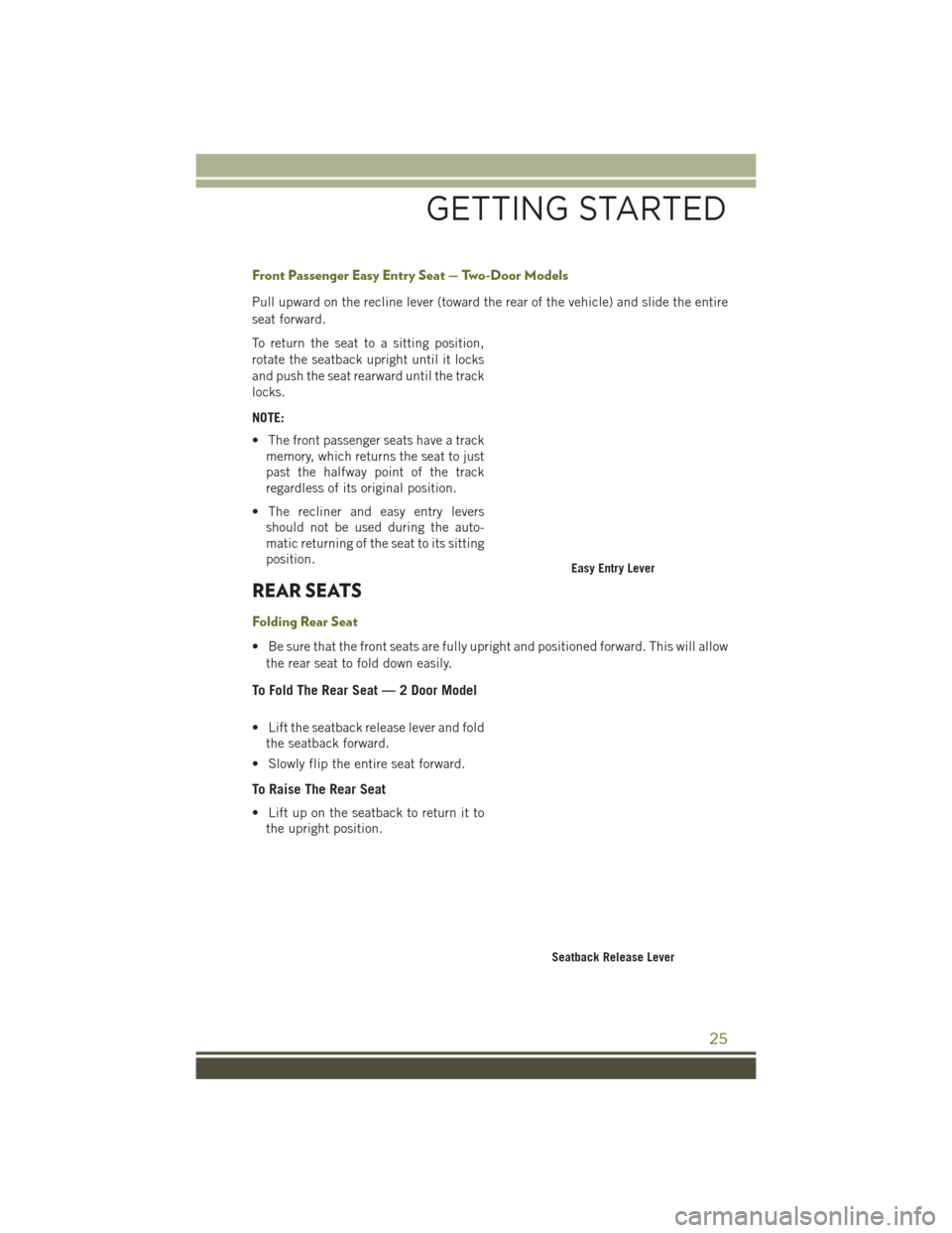
Pull upward on the recline lever (toward the rear of the vehicle) and slide the entire
seat forward.
To return the seat to a sitting position,
rotate the seatback upright until it locks
and push the seat rearward until the track
locks.
NOTE:
• The front passenger seats have a trackmemory, which returns the seat to just
past the halfway point of the track
regardless of its original position.
• The recliner and easy entry levers should not be used during the auto-
matic returning of the seat to its sitting
position.
REAR SEATS
Folding Rear Seat
• Be sure that the front seats are fully upright and positioned forward. This will allow
the rear seat to fold down easily.
To Fold The Rear Seat — 2 Door Model
• Lift the seatback release lever and foldthe seatback forward.
• Slowly flip the entire seat forward.
To Raise The Rear Seat
• Lift up on the seatback to return it to the upright position.
Easy Entry Lever
Seatback Release Lever
GETTING STARTED
25
Page 31 of 156
• Rotate the center portion of the lever upward to the next detent position tobrighten the odometer and radio controls when the parking lights or headlights are
on.
• Rotate the center portion of the lever upward to the last detent to turn on the interior lighting.
Flash-To-Pass
You can signal another vehicle with your headlights by lightly pulling the multifunc-
tion lever toward you. This will turn on the high beams headlights until the lever is
released.
High/Low Beam Switch
Push the multifunction lever away from you to switch the headlights to high beam.
Pull the lever toward you, to switch the headlights back to low beam.
Front Fog Lights
The front fog light switch is located on the multifunction lever. To activate the front
fog lights, turn on the parking or low beam headlights and pull out the end of the
lever.
NOTE:
The fog lights will only operate with the parking lights or the headlights on low beam.
Selecting high beam headlights will turn off the fog lights.
Turn Signals
Move the multifunction lever up or down and the arrows on each side of the
instrument cluster flash to show proper operation of the front and rear turn signal
lights.
NOTE:
• If either light remains on and does not flash, or there is a very fast flash rate, checkfor a defective outside light bulb. If an indicator fails to light when the lever is
moved, it would suggest that the indicator bulb is defective.
• A tone will chime if the turn signals are left on for more than 1 mile (2 km).
Lane Change Assist
Tap the lever up or down once, without moving beyond the detent, and the turn signal
(right or left) will flash three times then automatically turn off.
OPERATING YOUR VEHICLE
29
Page 32 of 156
WIPER/WASHER LEVER
Windshield Wiper Operation
Rotate the end of the lever upward to the
second detent past the intermittent set-
tings for low-speed wiper operation. Ro-
tate the end of the lever upward to the
third detent past the intermittent settings
for high-speed wiper operation.
CAUTION!
In cold weather, always turn off the wiper switch and allow the wipers to return to
the park position before turning off the engine. If the wiper switch is left on and the
wipers freeze to the windshield, damage to the wiper motor may occur when the
vehicle is restarted.
Intermittent Wiper System
Use the intermittent wiper when weather conditions make a single wiping cycle, with
a variable pause between cycles, desirable. Rotate the end of the lever to the first
detent position for one of five intermittent settings. The delay cycle can be set
anywhere between 1 to 18 seconds.
NOTE:
The wiper delay times depend on vehicle speed. If the vehicle is moving less than
10 mph (16 km/h), delay times will be doubled.
Windshield Washers
To use the washer, pull the lever toward you and hold while spray is desired. If the
lever is pulled while in the delay range, the wiper will start and continue to operate
for two or three wipe cycles after the lever is released, and then resume the
intermittent interval previously selected.
If the lever is pulled while in the off position, the wipers will operate for two or three
wipe cycles and then turn off.
Wiper/Washer Lever
OPERATING YOUR VEHICLE
30
Page 96 of 156
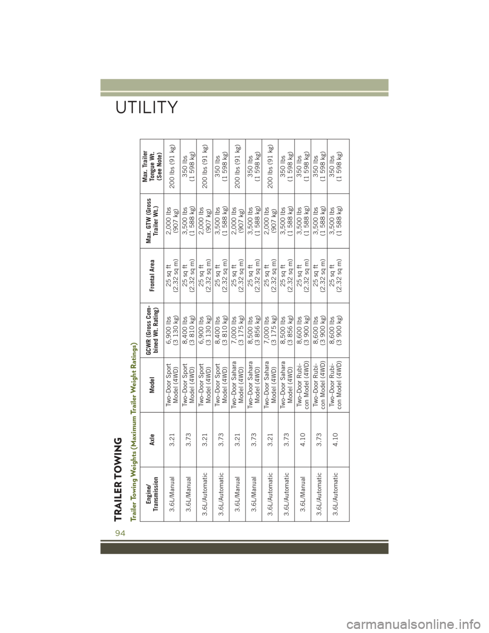
TRAILER TOWINGTrailer Towing Weights (Maximum Trailer Weight Ratings)
Engine/
Transmission Axle Model GCWR (Gross Com-
bined Wt. Rating) Frontal AreaMax. GTW (Gross
Trailer Wt.) Max. Trailer
Tongue Wt.(See Note)
3.6L/Manual 3.21 Two–Door Sport
Model (4WD) 6,900 lbs
(3 130 kg) 25 sq ft
(2.32 sq m) 2,000 lbs
(907 kg) 200 lbs (91 kg)
3.6L/Manual 3.73 Two–Door Sport
Model (4WD) 8,400 lbs
(3 810 kg) 25 sq ft
(2.32 sq m) 3,500 lbs
(1 588 kg) 350 lbs
(1 598 kg)
3.6L/Automatic 3.21 Two–Door Sport
Model (4WD) 6,900 lbs
(3 130 kg) 25 sq ft
(2.32 sq m) 2,000 lbs
(907 kg) 200 lbs (91 kg)
3.6L/Automatic 3.73 Two–Door Sport
Model (4WD) 8,400 lbs
(3 810 kg) 25 sq ft
(2.32 sq m) 3,500 lbs
(1 588 kg) 350 lbs
(1 598 kg)
3.6L/Manual 3.21 Two–Door Sahara
Model (4WD) 7,000 lbs
(3 175 kg) 25 sq ft
(2.32 sq m) 2,000 lbs
(907 kg) 200 lbs (91 kg)
3.6L/Manual 3.73 Two–Door Sahara
Model (4WD) 8,500 lbs
(3 856 kg) 25 sq ft
(2.32 sq m) 3,500 lbs
(1 588 kg) 350 lbs
(1 598 kg)
3.6L/Automatic 3.21 Two–Door Sahara
Model (4WD) 7,000 lbs
(3 175 kg) 25 sq ft
(2.32 sq m) 2,000 lbs
(907 kg) 200 lbs (91 kg)
3.6L/Automatic 3.73 Two–Door Sahara
Model (4WD) 8,500 lbs
(3 856 kg) 25 sq ft
(2.32 sq m) 3,500 lbs
(1 588 kg) 350 lbs
(1 598 kg)
3.6L/Manual 4.10 Two–Door Rubi-
con Model (4WD) 8,600 lbs
(3 900 kg) 25 sq ft
(2.32 sq m) 3,500
lbs
(1 588 kg) 350 lbs
(1 598 kg)
3.6L/Automatic 3.73 Two–Door Rubi-
con Model (4WD) 8,600 lbs
(3 900 kg) 25 sq ft
(2.32 sq m) 3,500 lbs
(1 588 kg) 350 lbs
(1 598 kg)
3.6L/Automatic 4.10 Two–Door Rubi-
con Model (4WD) 8,600 lbs
(3 900 kg) 25 sq ft
(2.32 sq m) 3,500 lbs
(1 588 kg) 350 lbs
(1 598 kg)
UTILITY
94
Page 98 of 156
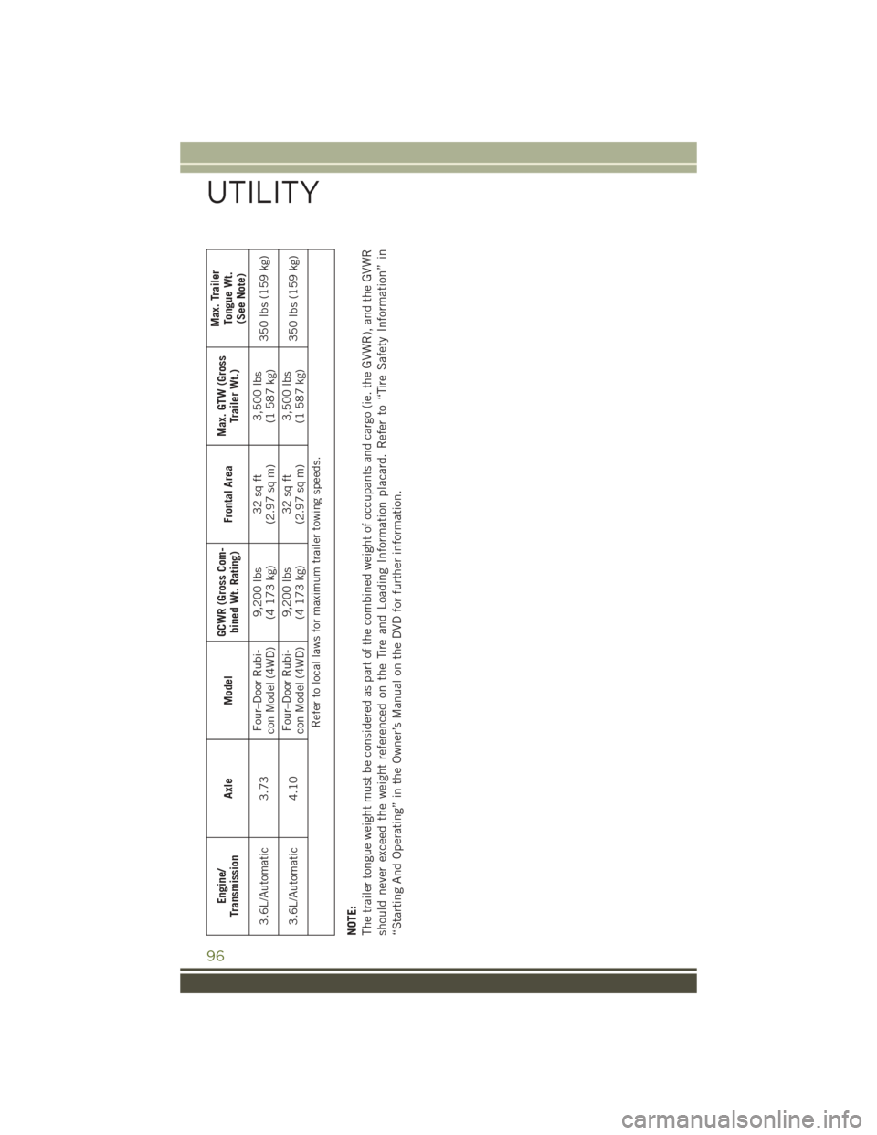
Engine/
Transmission Axle Model GCWR (Gross Com-
bined Wt. Rating) Frontal AreaMax. GTW (Gross
Trailer Wt.) Max. Trailer
Tongue Wt.(See Note)
3.6L/Automatic 3.73 Four–Door Rubi-
con Model (4WD) 9,200 lbs
(4 173 kg) 32 sq ft
(2.97 sq m) 3,500 lbs
(1 587 kg) 350 lbs (159 kg)
3.6L/Automatic 4.10 Four–Door Rubi-
con Model (4WD) 9,200 lbs
(4 173 kg) 32 sq ft
(2.97 sq m) 3,500 lbs
(1 587 kg) 350 lbs (159 kg)
Refer to local laws for maximum trailer towing speeds.
NOTE:
The trailer tongue weight must be considered as part of the combined weight of occupants and cargo (ie. the GVWR), and the GVWR
should never exceed the weight referenced on the Tire and Loading Information placard. Refer to “Tire Safety Information” in
“Starting And Operating” in the Owner’s Manual on the DVD for further information.
UTILITY
96
Page 99 of 156
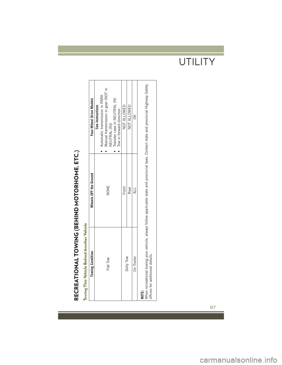
RECREATIONAL TOWING (BEHIND MOTORHOME, ETC.)Towing This Vehicle Behind Another Vehicle
Towing ConditionWheels OFF the Ground Four-Wheel Drive Models
Flat Tow NONESee Instructions
• Automatic transmission in PARK
• Manual transmission in gear (NOT in
NEUTRAL [N])
• Transfer case in NEUTRAL (N)
• Tow in forward direction
Dolly Tow Front
NOT ALLOWED
Rear NOT ALLOWED
On Trailer ALLOK
NOTE:
When recreational towing your vehicle, always follow applicable state and provincial laws. Contact state and provincial Highway Safety
offices for additional details.
UTILITY
97
Page 100 of 156
Recreational Towing — Four-Wheel Drive Models
NOTE:
The transfer case must be shifted intoNEUTRAL (N),automatic transmission must be
shifted into PARK,and manual transmission must be placed in gear (NOT in
NEUTRAL) for recreational towing.
CAUTION!
• DO NOT dolly tow any 4WD vehicle. Towing with only one set of wheels on the ground (front or rear) will cause severe transmission and/or transfer case
damage. Tow with all four wheels either ON the ground, or OFF the ground
(using a vehicle trailer).
• Tow only in the forward direction. Towing this vehicle backwards can cause
severe damage to the transfer case.
• Automatic transmissions must be placed in PARK for recreational towing.
• Manual transmissions must be placed in gear (not in Neutral) for recreational
towing.
• Before recreational towing, perform the procedure outlined under “Shifting
Into NEUTRAL (N)” to be certain that the transfer case is fully in NEUTRAL
(N). Otherwise, internal damage will result.
• Towing this vehicle in violation of the above requirements can cause severe
transmission and/or transfer case damage. Damage from improper towing is
not covered under the New Vehicle Limited Warranty.
• Do not use a bumper-mounted clamp-on tow bar on your vehicle. The bumper
face bar will be damaged.
Shifting Into NEUTRAL (N)
Use the following procedure to prepare your vehicle for recreational towing.
WARNING!
You or others could be injured or killed if you leave the vehicle unattended with the
transfer case in the NEUTRAL (N) position without first fully engaging the parking
brake. The transfer case NEUTRAL (N) position disengages both the front and rear
drive shaft from the powertrain, and will allow the vehicle to roll, even if the
automatic transmission is in PARK (or manual transmission is in gear). The
parking brake should always be applied when the driver is not in the vehicle.
CAUTION!
It is necessary to follow these steps to be certain that the transfer case is fully in
NEUTRAL (N) before recreational towing to prevent damage to internal parts.
UTILITY
98