lock JEEP WRANGLER 2016 JK / 3.G User Guide
[x] Cancel search | Manufacturer: JEEP, Model Year: 2016, Model line: WRANGLER, Model: JEEP WRANGLER 2016 JK / 3.GPages: 156, PDF Size: 8.82 MB
Page 3 of 156
INTRODUCTION/WELCOME
WELCOME FROM FCA US LLC....... 2
CONTROLS AT A GLANCE
DRIVER COCKPIT.............. 6
INSTRUMENT CLUSTER .......... 8
GETTING STARTED
KEYFOB ................... 10
REMOTE START.............. 11
VEHICLE SECURITY ALARM ....... 11
SEAT BELT SYSTEMS ........... 12
SUPPLEMENTAL RESTRAINT SYSTEM
(SRS) — AIR BAGS ............ 13
CHILD RESTRAINTS ............ 17
HEAD RESTRAINTS ............. 22
FRONT SEATS ................ 23
REAR SEATS ................. 25
TILT STEERING COLUMN ......... 26
HEATEDSEATS ............... 27
OPERATING YOUR VEHICLE
ENGINE BREAK-IN
RECOMMENDATIONS ........... 28
TURN SIGNAL/LIGHTS LEVER ...... 28
WIPER/WASHER LEVER .......... 30
ELECTRONIC SPEED CONTROL ..... 32
MANUAL CLIMATE CONTROLS ...... 35
AUTOMATIC TEMPERATURE CONTROLS
(ATC) ..................... 36
SUNRIDER AND SOFT TOP ........ 37
HARD TOP AND FREEDOM TOP ..... 49
DUAL TOP – IF EQUIPPED ........ 52
WIND BUFFETING ............. 53
ELECTRONICS
YOUR VEHICLE'S SOUND SYSTEM . . . 54
UCONNECT 130............... 56
UCONNECT 130 WITH SiriusXM SATELLITE
RADIO ..................... 58
UCONNECT 230 ............... 61
UCONNECT 430/430N ........... 64
SiriusXM SATELLITE RADIO/TRAVEL LINK.. 76STEERING WHEEL AUDIO CONTROLS.. 79
iPod/USB/MP3 CONTROL ......... 79
UCONNECT PHONE ............. 80
UCONNECT VOICE COMMAND ...... 83
BLUETOOTH STREAMING AUDIO .... 86
ELECTRONIC VEHICLE INFORMATION
CENTER (EVIC) ............... 86
PROGRAMMABLE FEATURES ....... 88
POWER INVERTER ............. 89
POWER OUTLETS ............. 90
OFF-ROAD CAPABILITIES
(4WD OPERATION)
COMMAND-TRAC/ROCK-TRAC ...... 92
AXLE LOCK (TRU-LOK) RUBICON ONLY . . 93ELECTRONIC SWAY BAR DISCONNECT –
RUBICON ONLY............... 93
UTILITY
TRAILER TOWING ............. 94
RECREATIONAL TOWING (BEHIND
MOTORHOME, ETC.) ............ 97
WHAT TO DO IN EMERGENCIES
ROADSIDE ASSISTANCE ......... 101
INSTRUMENT CLUSTER WARNING
LIGHTS ................... 101
INSTRUMENT CLUSTER INDICATOR
LIGHTS ................... 106
IF YOUR ENGINE OVERHEATS ..... 107
JACKING AND TIRE CHANGING .... 108
JUMP-STARTING PROCEDURES .... 113
EMERGENCY TOW HOOKS —
IF EQUIPPED ............... 115
SHIFT LEVER OVERRIDE ........ 116
TOWING A DISABLED VEHICLE .... 117
FREEING A STUCK VEHICLE ...... 119
ENHANCED ACCIDENT RESPONSE
SYSTEM (EARS) .............. 120
EVENT DATA RECORDER (EDR) .... 120
MAINTAINING YOUR VEHICLE
TO OPEN AND CLOSE THE HOOD . . . 121
ENGINE COMPARTMENT — 3.6L . . . 122
FLUID CAPACITIES............ 124
FLUIDS, LUBRICANTS, AND GENUINE
PARTS .................... 124
MAINTENANCE PROCEDURES ..... 126
MAINTENANCE SCHEDULE ....... 126
FUSES ................... 132
TIRES — GENERAL INFORMATION . . 135
REPLACEMENT BULBS ......... 138
CONSUMER ASSISTANCE
FCA US LLC CUSTOMER CENTER . . . 139FCA CANADA INC. CUSTOMER
CENTER................... 139
ASSISTANCE FOR THE HEARING
IMPAIRED ................. 139
PUBLICATIONS ORDERING ....... 139
REPORTING SAFETY DEFECTS IN THE
UNITEDSTATES .............. 140
MOPAR® ACCESSORIES AND
JEEP® PERFORMANCE PARTS
AUTHENTIC ACCESSORIES AND JEEP
PERFORMANCE PARTS BY MOPAR . . 141
FREQUENTLY ASKED
QUESTIONS
FREQUENTLY ASKED QUESTIONS . . . 142
INDEX.................. 144
TABLE OF CONTENTS
Page 5 of 156
When it comes to service, remember that your authorized dealer knows your vehicle
best, has factory-trained technicians and genuine MOPAR®parts, and cares about
your satisfaction.
VEHICLES SOLD IN CANADA
With respect to any vehicles sold in Canada, the name FCA US LLC shall be deemed
to be deleted and the name FCA Canada Inc. used in substitution (excluding legal
lines).
WARNING!
• Pedals that cannot move freely can cause loss of vehicle control and increase the risk of serious personal injury.
• Always make sure that objects cannot fall into the driver foot well while the
vehicle is moving. Objects can become trapped under the brake pedal and
accelerator pedal causing a loss of vehicle control.
• Failure to properly follow floor mat installation or mounting can cause inter-
ference with the brake pedal and accelerator pedal operation causing loss of
control of the vehicle.
• Never leave children alone in a vehicle, or with access to an unlocked vehicle.
Allowing children to be in a vehicle unattended is dangerous for a number of
reasons. A child or others could be seriously or fatally injured. Children should
be warned not to touch the parking brake, brake pedal or the transmission gear
selector.
• Do not leave the key fob in or near the vehicle, or in a location accessible to
children. A child could operate power windows, other controls, or move the
vehicle.
• Never use the ‘PARK’ position as a substitute for the parking brake. Always
apply the parking brake fully when parked to guard against vehicle movement
and possible injury or damage.
• Refer to your Owner's Manual on the DVD for further details.
INTRODUCTION/WELCOME
3
Page 9 of 156
8. Switch Panel• Heated Seats pg. 27
• Hazard Warning Light
• Electronic Stability Control (ESC) OFF pg. 104
9. Shift Lever
10. Speed Control pg. 32
11. Ignition Switch
12. Electronic Vehicle Information Center (EVIC) Controls pg. 86
13. Door Locks
CONTROLS AT A GLANCE
7
Page 12 of 156
KEY FOB
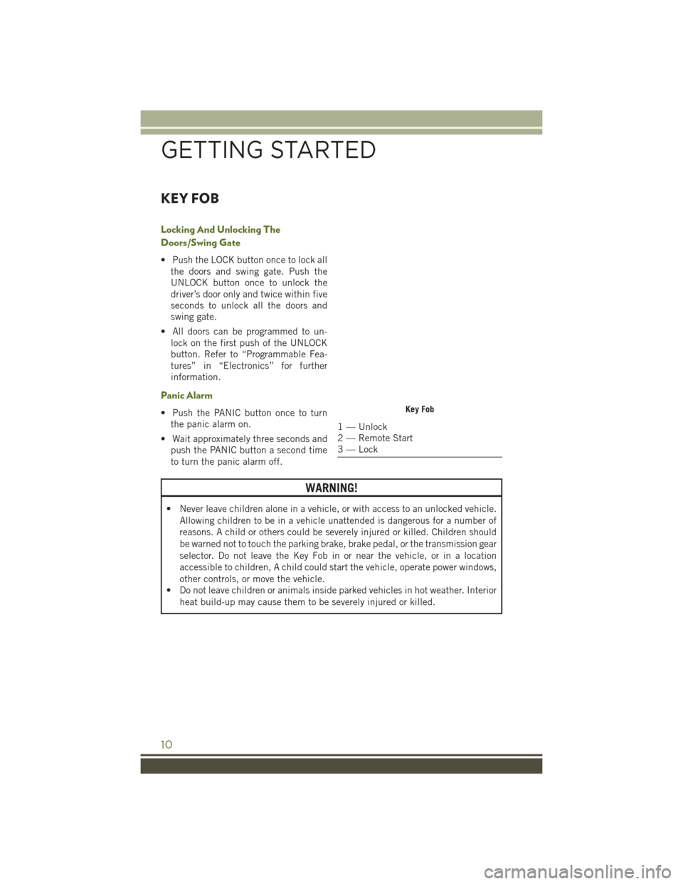
Locking And Unlocking The
Doors/Swing Gate
• Push the LOCK button once to lock allthe doors and swing gate. Push the
UNLOCK button once to unlock the
driver’s door only and twice within five
seconds to unlock all the doors and
swing gate.
• All doors can be programmed to un- lock on the first push of the UNLOCK
button. Refer to “Programmable Fea-
tures” in “Electronics” for further
information.
Panic Alarm
• Push the PANIC button once to turnthe panic alarm on.
• Wait approximately three seconds and push the PANIC button a second time
to turn the panic alarm off.
WARNING!
• Never leave children alone in a vehicle, or with access to an unlocked vehicle.
Allowing children to be in a vehicle unattended is dangerous for a number of
reasons. A child or others could be severely injured or killed. Children should
be warned not to touch the parking brake, brake pedal, or the transmission gear
selector. Do not leave the Key Fob in or near the vehicle, or in a location
accessible to children, A child could start the vehicle, operate power windows,
other controls, or move the vehicle.
• Do not leave children or animals inside parked vehicles in hot weather. Interior
heat build-up may cause them to be severely injured or killed.
Key Fob
1 — Unlock
2 — Remote Start
3 — Lock
GETTING STARTED
10
Page 13 of 156
REMOTE START
• Push the REMOTE START buttonon the Key Fob twice within five seconds.
Pushing the REMOTE START button a third time shuts the engine off.
• To drive the vehicle, push the UNLOCK button, insert the key in the ignition and turn to the ON/RUN position.
• With Remote Start, the engine will only run for 15 minutes (timeout) unless the ignition key is placed in the ON/RUN position.
• The vehicle must be started with the key after two consecutive timeouts.
WARNING!
• Do not start or run an engine in a closed garage or confined area. Exhaust gas contains Carbon Monoxide (CO) which is odorless and colorless. Carbon
Monoxide is poisonous and can cause you or others to be severely injured or
killed when inhaled.
• Keep Key Fob transmitters away from children. Operation of the Remote Start
System, windows, door locks or other controls could cause you and others to be
severely injured or killed.
VEHICLE SECURITY ALARM
The Vehicle Security Alarm monitors the vehicle doors for unauthorized entry and the
ignition for unauthorized operation. While the Vehicle Security Alarm is armed,
interior switches for door locks and decklid release are disabled. If something triggers
the alarm, the Vehicle Security Alarm will provide the following audible and visible
signals: the horn will pulse, the park lamps and/or turn signals will flash, and the
Vehicle Security Light in the instrument cluster will flash.
To Arm The System:
Lock the door using either the power door lock switch (one door must be open) or the
LOCK button on the Remote Keyless Entry (RKE) transmitter (doors can be open or
closed), and close all doors.
The Vehicle Security Light in the instrument cluster will flash for 16 seconds. This
shows that the Vehicle Security Alarm is arming. During this period, if a door is
opened, the ignition is cycled to ON/RUN, or the power door locks are unlocked in any
manner, the Vehicle Security Alarm will automatically disarm.
NOTE:
• The Vehicle Security Alarm will not arm if you lock the doors with the manual door
lock plungers.
• Once armed, the Vehicle Security Alarm disables the unlock switch on the driver door trim panel and passenger door trim panel.
GETTING STARTED
11
Page 14 of 156
To Disarm The System:
Push the Key Fob UNLOCK button or cycle the ignition to the ON/RUN position.
The Vehicle Security Alarm is designed to protect your vehicle. However, you can
create conditions where the Vehicle Security Alarm will give you a false alarm. If one
of the previously described arming sequences has occurred, the Vehicle Security
Alarm will arm regardless of whether you are in the vehicle or not. If you remain in the
vehicle and open a door, the alarm will sound. If this occurs, disarm the Vehicle
Security Alarm.
If the Vehicle Security Alarm is armed and the battery becomes disconnected, the
Vehicle Security Alarm will remain armed when the battery is reconnected. The
exterior lights will flash, and the horn will sound. If this occurs, disarm the Vehicle
Security Alarm.
SEAT BELT SYSTEMS
Lap/Shoulder Belts
• All seating positions in your vehicle are equipped with lap/shoulder belts.
• Be sure everyone in your vehicle is in a seat and using a seat belt properly.
• Position the lap belt so that it is snug and lies low across your hips, below yourabdomen. To remove slack in the lap belt portion, pull up on the shoulder belt. To
loosen the lap belt if it is too tight, tilt the latch plate and pull on the lap belt. A
snug seat belt reduces the risk of sliding under the seat belt in a collision.
• Position the shoulder belt across the shoulder and chest with minimal, if any slack so that it is comfortable and not resting on your neck. The retractor will withdraw
any slack in the shoulder belt.
Seat Belt Pretensioner
• The front seat belt system is equipped with pretensioning devices that aredesigned to remove slack from the seat belt in the event of a collision.
• A deployed pretensioner or a deployed air bag must be replaced immediately.
GETTING STARTED
12
Page 17 of 156
Supplemental Side Air Bags
• This vehicle is equipped with Supplemental Seat-Mounted Side Air Bags (SABs)that are located in the outboard side of the front seats. The SABs are marked with
a SRS AIRBAG or AIRBAG label sewn into the outboard side of the seats.
• SABs are designed to activate in certain side impacts. The Occupant Restraint Controller (“ORC”) determines whether the deployment of the SAB in a particular
impact event is appropriate, based on the severity and type of collision. Vehicle
damage by itself is not a good indicator of whether or not SABs should have
deployed.
WARNING!
• SABs need room to inflate. Do not lean against the door or window. Sit upright in the center of the seat.
• Being too close to the SABs during deployment could cause you to be severely
injured or killed.
• Relying on the SABs alone could lead to more severe injuries in a collision. The
SABs work with your seat belt to restrain you properly. In some collisions, SABs
won’t deploy at all. Always wear your seat belt even though you have SABs.
• Do not use accessory seat covers or place objects between you and the SABs;
the performance could be adversely affected and/or objects could be pushed
into you, causing serious injury.
Enhanced Accident Response System
In the event of an impact, if the communication network remains intact, and the
power remains intact, depending on the nature of the event, the ORC will determine
whether to have the Enhanced Accident Response System perform the following
functions:
• Cut off fuel to the engine.
• Flash hazard lights as long as the battery has power or until the hazard light button
is pushed. The hazard lights can be deactivated by pushing the hazard light
button.
• Turn on the interior lights, which remain on as long as the battery has power.
• Unlock the power door locks.
Enhanced Accident Response System Reset Procedure
In order to reset the Enhanced Accident Response System functions after an event,
the ignition switch must be changed from ignition START or ON/RUN to ignition OFF.
Carefully check the vehicle for fuel leaks in the engine compartment and on the
ground near the engine compartment and fuel tank before resetting the system and
starting the engine.
GETTING STARTED
15
Page 21 of 156
Center Seat LATCH (Two-Door Models)
WARNING!
This vehicle does not have a center seating position. Do not use the center lower
LATCH anchorages to install a child seat in the center of the back seat.
Center Seat LATCH (Four-Door Models)
Do not install child restraints with rigid lower attachments in the center seating
position. Only install this type of child restraint in the outboard seating positions.
Child restraints with flexible, webbing mounted lower attachments can be installed
in any rear seating position. In the center position, the inner anchorages are 19
inches (484 mm) apart.
Installing The Child Restraint Using The LATCH Lower Anchors
NOTE:
Never “share” a LATCH anchorage with two or more child restraints.
1. Loosen the adjusters on the lower straps and on the tether strap of the child seatso that you can more easily attach the hooks or connectors to the vehicle
anchorages.
2. Attach the lower hooks or connectors of the child restraint to the lower anchorages in the selected seating position.
3. If the child restraint has a tether strap, connect it to the top tether anchorage. See below for directions to attach a tether anchor.
4. Tighten all of the straps as you push the child restraint rearward and downward into the seat. Remove slack in the straps according to the child restraint
manufacturer’s instructions.
5. Test that the child restraint is installed tightly by pulling back and forth on the child seat at the belt path. It should not move more than 1 inch (25.4 mm) in any
direction.
Installing The Child Restraint Using The Vehicle Seat Belts
The seat belts in the passenger seating positions are equipped with a Switchable
Automatic Locking Retractor (ALR) that is designed to keep the lap portion of the
seat belt tight around the child restraint. Any seat belt system will loosen with time,
so check the belt occasionally, and pull it tight if necessary.
GETTING STARTED
19
Page 22 of 156
Tether Anchorage Weight Limit
Always use the tether anchor when using the seat belt to install a forward facing child
restraint, up to the recommended weight limit of the child restraint.
To Install A Child Seat Using An ALR:
1. Pull enough of the seat belt webbing from the retractor to pass it through the beltpath of the child restraint. Do not twist the belt webbing in the belt path.
2. Slide the latch plate into the buckle until you hear a “click.”
3. Pull on the webbing to make the lap portion tight against the child seat.
4. To lock the seat belt, pull down on the shoulder part of the belt until you have pulled all the seat belt webbing out of the retractor. Then, allow the webbing to
retract back into the retractor. As the webbing retracts, you will hear a clicking
sound. This means the seat belt is now in the Automatic Locking mode.
5. Try to pull the webbing out of the retractor. If it is locked, you should not be able to pull out any webbing. If the retractor is not locked, repeat the last step.
6. Finally, pull up on any extra webbing to tighten the lap portion around the child restraint while you push the child restraint rearward and downward into the
vehicle seat.
7. If the child restraint has a top tether strap and the seating position has a top tether anchorage, connect the tether strap to the anchorage and tighten the tether strap.
See below for directions to attach a tether anchor.
8. Test that the child restraint is installed tightly by pulling back and forth on the child seat at the belt path. It should not move more than 1 inch (25.4 mm) in any
direction.
Installing The Top Tether Strap (With Either Lower Anchors Or Vehicle Seat
Belt):
When installing a forward-facing child restraint, always secure the top tether strap,
up to the tether anchor weight limit, whether the child restraint is installed with the
lower anchors or the vehicle seat belt.
Tether Strap Installation
1. Route the tether strap to provide the most direct path for the strap between theanchor and the child seat.
2. If your vehicle is equipped with adjustable rear head restraints, raise the head restraint, and where possible, route the tether strap under the head restraint and
between the two posts. If not possible, lower the head restraint and pass the
tether strap around the outboard side of the head restraint.
GETTING STARTED
20
Page 24 of 156
HEAD RESTRAINTS
Head restraints are designed to reduce the risk of injury by restricting head
movement in the event of a rear impact. Head restraints should be adjusted so that
the top of the head restraint is located above the top of your ear.
WARNING!
The head restraints for all occupants must be properly installed and adjusted prior
to operating the vehicle or occupying a seat. Head restraints should never be
adjusted while the vehicle is in motion. Driving a vehicle with the head restraints
improperly adjusted or removed could cause serious injury or death in the event of
a collision.
Front Head Restraints
To raise the head restraint, pull upward on the head restraint. To lower the head
restraint, push the adjustment button located on the base of the head restraint, and
push downward on the head restraint.
To remove the head restraint, raise it as far as it can go then push the adjustment
button and the release button at the base of each post while pulling the head restraint
up. To reinstall the head restraint, put the head restraint posts into the holes and
push downward. Then adjust it to the appropriate height.
WARNING!
• A loose head restraint thrown forward in a collision or hard stop could causeserious injury or death to occupants of the vehicle. Always securely stow
removed head restraints in a location outside the occupant compartment.
• ALL the head restraints MUST be reinstalled in the vehicle to properly protect
the occupants. Follow the re-installation instructions above prior to operating
the vehicle or occupying a seat.
NOTE:
Do not reposition the head restraint 180 degrees to the incorrect position in an
attempt to gain additional clearance to the back of the head.
Rear Head Restraints—2DoorM odel
The rear seat head restraints are not adjustable. They can be removed to make it
easier to take out the rear seat. To remove the head restraint, push the button on each
of the two head restraint guides and pull upward on the head restraint. Replace the
head restraint before driving the vehicle with passengers in the rear seat. To replace
the head restraint, insert the head restraint rods into the guides and push downward
on the head restraint until locked.
GETTING STARTED
22