clock JEEP WRANGLER 2020 Owner handbook (in English)
[x] Cancel search | Manufacturer: JEEP, Model Year: 2020, Model line: WRANGLER, Model: JEEP WRANGLER 2020Pages: 276, PDF Size: 4.47 MB
Page 37 of 276
Icon Description
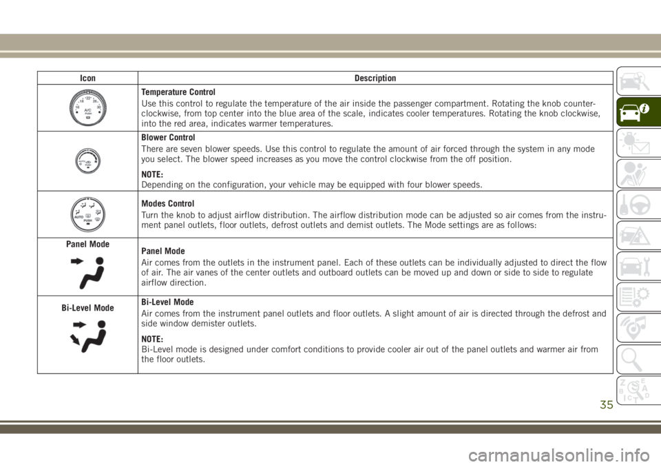
Temperature Control
Use this control to regulate the temperature of the air inside the passenger compartment. Rotating the knob counter-
clockwise, from top center into the blue area of the scale, indicates cooler temperatures. Rotating the knob clockwise,
into the red area, indicates warmer temperatures.
Blower Control
There are seven blower speeds. Use this control to regulate the amount of air forced through the system in any mode
you select. The blower speed increases as you move the control clockwise from the off position.
NOTE:
Depending on the configuration, your vehicle may be equipped with four blower speeds.
Modes Control
Turn the knob to adjust airflow distribution. The airflow distribution mode can be adjusted so air comes from the instru-
ment panel outlets, floor outlets, defrost outlets and demist outlets. The Mode settings are as follows:
Panel Mode
Panel Mode
Air comes from the outlets in the instrument panel. Each of these outlets can be individually adjusted to direct the flow
of air. The air vanes of the center outlets and outboard outlets can be moved up and down or side to side to regulate
airflow direction.
Bi-Level Mode
Bi-Level Mode
Air comes from the instrument panel outlets and floor outlets. A slight amount of air is directed through the defrost and
side window demister outlets.
NOTE:
Bi-Level mode is designed under comfort conditions to provide cooler air out of the panel outlets and warmer air from
the floor outlets.
35
Page 50 of 276
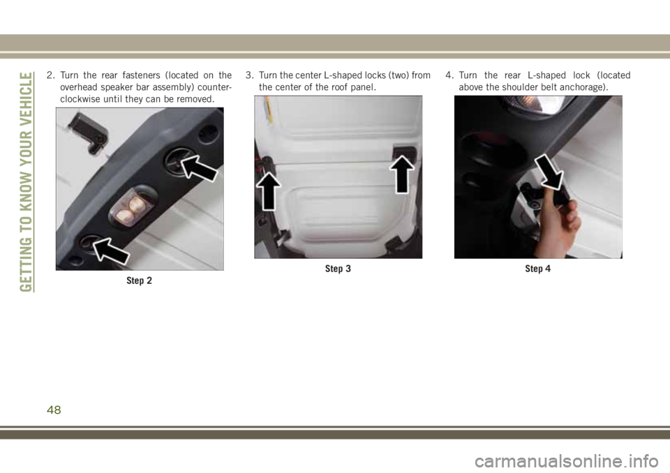
2. Turn the rear fasteners (located on the
overhead speaker bar assembly) counter-
clockwise until they can be removed.3. Turn the center L-shaped locks (two) from
the center of the roof panel.4. Turn the rear L-shaped lock (located
above the shoulder belt anchorage).
Step 2
Step 3Step 4
GETTING TO KNOW YOUR VEHICLE
48
Page 149 of 276
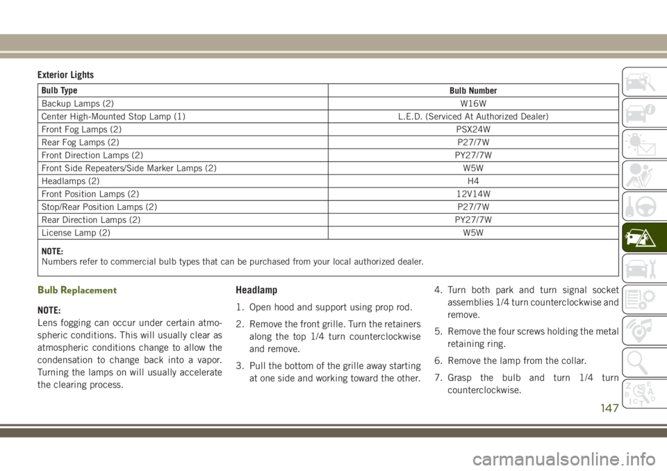
Exterior Lights
Bulb Type
Bulb Number
Backup Lamps (2)W16W
Center High-Mounted Stop Lamp (1) L.E.D. (Serviced At Authorized Dealer)
Front Fog Lamps (2)PSX24W
Rear Fog Lamps (2)P27/7W
Front Direction Lamps (2)PY27/7W
Front Side Repeaters/Side Marker Lamps (2) W5W
Headlamps (2)H4
Front Position Lamps (2)12V14W
Stop/Rear Position Lamps (2)P27/7W
Rear Direction Lamps (2)PY27/7W
License Lamp (2)W5W
NOTE:
Numbers refer to commercial bulb types that can be purchased from your local authorized dealer.
Bulb Replacement
NOTE:
Lens fogging can occur under certain atmo-
spheric conditions. This will usually clear as
atmospheric conditions change to allow the
condensation to change back into a vapor.
Turning the lamps on will usually accelerate
the clearing process.
Headlamp
1. Open hood and support using prop rod.
2. Remove the front grille. Turn the retainers
along the top 1/4 turn counterclockwise
and remove.
3. Pull the bottom of the grille away starting
at one side and working toward the other.4. Turn both park and turn signal socket
assemblies 1/4 turn counterclockwise and
remove.
5. Remove the four screws holding the metal
retaining ring.
6. Remove the lamp from the collar.
7. Grasp the bulb and turn 1/4 turn
counterclockwise.
147
Page 150 of 276
8. Pull the bulb from the housing.
9. Push connector locking tab to the unlock
position.
10. Remove connector from bulb.
11. Push connector onto new bulb base, and
push the connector locking tab to the
lock position.
CAUTION!
Do not touch the new bulb with your fin-
gers. Oil contamination will severely
shorten bulb life. If the bulb comes in
contact with any oily surface, clean the
bulb with rubbing alcohol.
12. Reinstall bulb housing. Rotate the bulb
1/4 turn clockwise.
Front Park/Turn Signal
1. Remove the front grille. Turn the retainers
along the top 1/4 turn counterclockwise
and remove.
2. Pull the bottom of the grille away starting
at one side and working toward the other.3. Turn the socket assembly 1/4 turn coun-
terclockwise and remove from housing.
Pull the bulb straight from the socket to
replace.
Front Side Marker
1. Reach under the front fender flare and
locate the front side marker socket.
2. Turn the socket assembly counterclock-
wise 1/3 turn and remove it from the
housing. Pull the bulb straight from the
socket to replace.
Front Fog Lamp
1. Reach under the vehicle to access the
back of the front fog lamp.
2. Disconnect the wire harness connector
from the front fog lamp connector
receptacle.
3. Firmly grasp the bulb by the two latch
features and squeeze them together to
unlock the bulb from the back of the front
fog lamp housing.4. Pull the bulb straight out from the keyed
opening in the housing and then connect
the replacement bulb.
CAUTION!
Do not touch the new bulb with your fin-
gers. Oil contamination will severely
shorten bulb life. If the bulb comes in
contact with any oily surface, clean the
bulb with rubbing alcohol.
Rear Fog Lamp
1. Reach under the vehicle to access the
back of the rear fog lamp.
2. Turn the socket assembly counterclock-
wise 1/4 turn and remove it from the
housing. Pull the bulb straight from the
socket to replace.IN CASE OF EMERGENCY
148
Page 151 of 276
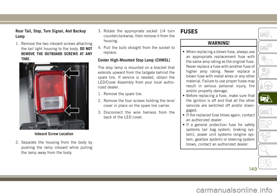
Rear Tail, Stop, Turn Signal, And Backup
Lamp
1. Remove the two inboard screws attaching
the tail light housing to the body.DO NOT
REMOVE THE OUTBOARD SCREWS AT ANY
TIME.
2. Separate the housing from the body by
pushing the lamp inboard while pulling
the lamp away from the body.3. Rotate the appropriate socket 1/4 turn
counterclockwise, then remove it from the
housing.
4. Pull the bulb straight from the socket to
replace.
Center High-Mounted Stop Lamp (CHMSL)
The stop lamp is mounted on a bracket that
extends upward from the tailgate behind the
spare tire. If service is needed, obtain the
LED/Cover Assembly from your local autho-
rized dealer.
1. Remove the spare tire.
2. Remove the four screws holding the lens/
cover in place on the spare tire carrier.
3. Disconnect the wire harness from the
back of the LED cover.
FUSES
WARNING!
• When replacing a blown fuse, always use
an appropriate replacement fuse with
the same amp rating as the original fuse.
Never replace a fuse with another fuse of
higher amp rating. Never replace a
blown fuse with metal wires or any other
material. Failure to use proper fuses may
result in serious personal injury, fire
and/or property damage.
• Before replacing a fuse, make sure that
the ignition is off and that all the other
services are switched off and/or disen-
gaged.
• If the replaced fuse blows again, contact
an authorized dealer.
• If a general protection fuse for safety
systems (air bag system, braking sys-
tem), power unit systems (engine sys-
tem, gearbox system) or steering system
blows, contact an authorized dealer.
Inboard Screw Location
149
Page 153 of 276
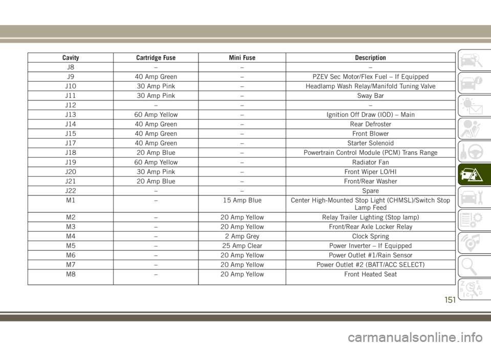
Cavity Cartridge Fuse Mini Fuse Description
J8 – – –
J9 40 Amp Green – PZEV Sec Motor/Flex Fuel – If Equipped
J10 30 Amp Pink – Headlamp Wash Relay/Manifold Tuning Valve
J11 30 Amp Pink – Sway Bar
J12 – – –
J13 60 Amp Yellow – Ignition Off Draw (IOD) – Main
J14 40 Amp Green – Rear Defroster
J15 40 Amp Green – Front Blower
J17 40 Amp Green – Starter Solenoid
J18 20 Amp Blue – Powertrain Control Module (PCM) Trans Range
J19 60 Amp Yellow – Radiator Fan
J20 30 Amp Pink – Front Wiper LO/HI
J21 20 Amp Blue – Front/Rear Washer
J22 – – Spare
M1 – 15 Amp Blue Center High-Mounted Stop Light (CHMSL)/Switch Stop
Lamp Feed
M2 – 20 Amp Yellow Relay Trailer Lighting (Stop lamp)
M3 – 20 Amp Yellow Front/Rear Axle Locker Relay
M4 – 2 Amp Grey Clock Spring
M5 – 25 Amp Clear Power Inverter – If Equipped
M6 – 20 Amp Yellow Power Outlet #1/Rain Sensor
M7 – 20 Amp Yellow Power Outlet #2 (BATT/ACC SELECT)
M8 – 20 Amp Yellow Front Heated Seat
151
Page 156 of 276
JACKING AND TIRE
CHANGING
WARNING!
• Do not attempt to change a tire on the
side of the vehicle close to moving traf-
fic. Pull far enough off the road to avoid
the danger of being hit when operating
the jack or changing the wheel.
• Being under a jacked-up vehicle is dan-
gerous. The vehicle could slip off the
jack and fall on you. You could be
crushed. Never put any part of your body
under a vehicle that is on a jack. If you
need to get under a raised vehicle, take
it to a service center where it can be
raised on a lift.
• Never start or run the engine while the
vehicle is on a jack.
• The jack is designed to be used as a tool
for changing tires only. The jack should
not be used to lift the vehicle for service
purposes. The vehicle should be jacked
on a firm level surface only. Avoid ice or
slippery areas.
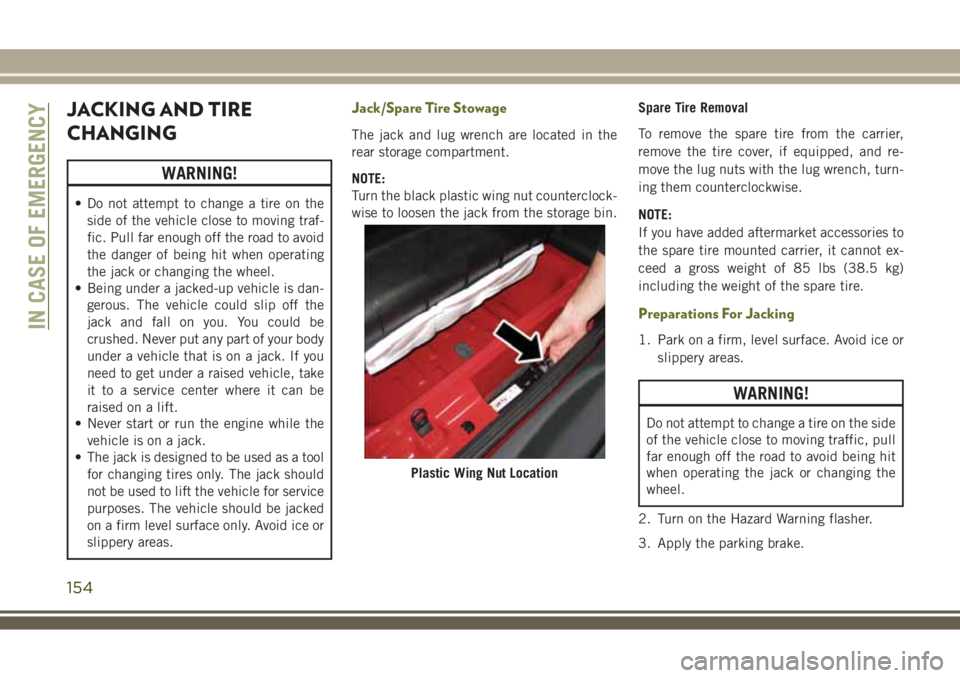
Jack/Spare Tire Stowage
The jack and lug wrench are located in the
rear storage compartment.
NOTE:
Turn the black plastic wing nut counterclock-
wise to loosen the jack from the storage bin.Spare Tire Removal
To remove the spare tire from the carrier,
remove the tire cover, if equipped, and re-
move the lug nuts with the lug wrench, turn-
ing them counterclockwise.
NOTE:
If you have added aftermarket accessories to
the spare tire mounted carrier, it cannot ex-
ceed a gross weight of 85 lbs (38.5 kg)
including the weight of the spare tire.
Preparations For Jacking
1. Park on a firm, level surface. Avoid ice or
slippery areas.
WARNING!
Do not attempt to change a tire on the side
of the vehicle close to moving traffic, pull
far enough off the road to avoid being hit
when operating the jack or changing the
wheel.
2. Turn on the Hazard Warning flasher.
3. Apply the parking brake.
Plastic Wing Nut Location
IN CASE OF EMERGENCY
154
Page 158 of 276
CAUTION!
Do not attempt to raise the vehicle by
jacking on locations other than those indi-
cated.
1. Remove the spare tire, jack and tools from
the stored location.
2. Loosen (but do not remove) the wheel lug
nuts by turning them to the left one turn
while the wheel is still on the ground.
3. Assemble the jack and jacking tools. Con-
nect the jack handle driver to the exten-
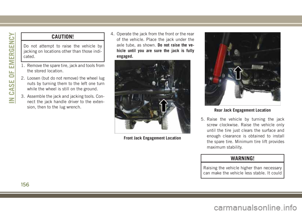
sion, then to the lug wrench.4. Operate the jack from the front or the rear
of the vehicle. Place the jack under the
axle tube, as shown.Do not raise the ve-
hicle until you are sure the jack is fully
engaged.
5. Raise the vehicle by turning the jack
screw clockwise. Raise the vehicle only
until the tire just clears the surface and
enough clearance is obtained to install
the spare tire. Minimum tire lift provides
maximum stability.
WARNING!
Raising the vehicle higher than necessary
can make the vehicle less stable. It could
Front Jack Engagement Location
Rear Jack Engagement Location
IN CASE OF EMERGENCY
156
Page 159 of 276
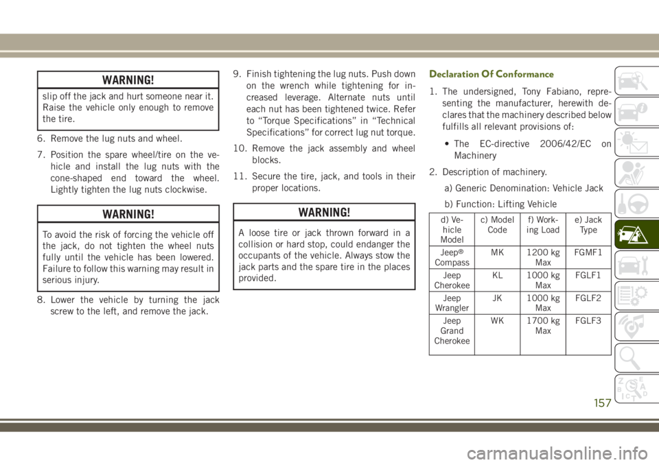
WARNING!
slip off the jack and hurt someone near it.
Raise the vehicle only enough to remove
the tire.
6. Remove the lug nuts and wheel.
7. Position the spare wheel/tire on the ve-
hicle and install the lug nuts with the
cone-shaped end toward the wheel.
Lightly tighten the lug nuts clockwise.
WARNING!
To avoid the risk of forcing the vehicle off
the jack, do not tighten the wheel nuts
fully until the vehicle has been lowered.
Failure to follow this warning may result in
serious injury.
8. Lower the vehicle by turning the jack
screw to the left, and remove the jack.9. Finish tightening the lug nuts. Push down
on the wrench while tightening for in-
creased leverage. Alternate nuts until
each nut has been tightened twice. Refer
to “Torque Specifications” in “Technical
Specifications” for correct lug nut torque.
10. Remove the jack assembly and wheel
blocks.
11. Secure the tire, jack, and tools in their
proper locations.
WARNING!
A loose tire or jack thrown forward in a
collision or hard stop, could endanger the
occupants of the vehicle. Always stow the
jack parts and the spare tire in the places
provided.
Declaration Of Conformance
1. The undersigned, Tony Fabiano, repre-
senting the manufacturer, herewith de-
clares that the machinery described below
fulfills all relevant provisions of:
• The EC-directive 2006/42/EC on
Machinery
2. Description of machinery.
a) Generic Denomination: Vehicle Jack
b) Function: Lifting Vehicle
d) Ve-
hicle
Modelc) Model
Codef) Work-
ing Loade) Jack
Type
Jeep
®
CompassMK 1200 kg
MaxFGMF1
Jeep
CherokeeKL 1000 kg
MaxFGLF1
Jeep
WranglerJK 1000 kg
MaxFGLF2
Jeep
Grand
CherokeeWK 1700 kg
MaxFGLF3
157
Page 217 of 276
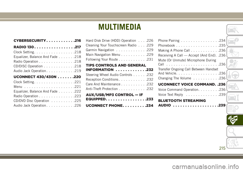
MULTIMEDIA
CYBERSECURITY............216
RADIO 130.................217
Clock Setting.................218
Equalizer, Balance And Fade.......218
Radio Operation...............218
CD/DISC Operation.............218
Audio Jack Operation............219
UCONNECT 430/430N.......220
Clock Setting.................221
Menu.....................221
Equalizer, Balance And Fade.......222
Radio Operation...............223
CD/DVD Disc Operation..........225
Audio Jack Operation............226Hard Disk Drive (HDD) Operation. . . .226
Cleaning Your Touchscreen Radio. . . .229
Garmin Navigation.............229
Main Navigation Menu...........229
Following Your Route............231
TIPS CONTROLS AND GENERAL
INFORMATION.............232
Steering Wheel Audio Controls......232
Reception Conditions............232
Care And Maintenance...........232
Anti-Theft Protection............232
AUX/USB/MP3 CONTROL — IF
EQUIPPED.................233
UCONNECT PHONE..........234
Phone Pairing................234
Phonebook..................235
Making A Phone Call............236
Receiving A Call — Accept (And End). .236
Mute (Or Unmute) Microphone During
Call......................236
Transfer Ongoing Call Between Handset
And Vehicle..................236
Changing The Volume...........236
UCONNECT VOICE COMMAND. .236
Voice Command Operation.........236
Voice Text Reply..............239
BLUETOOTH STREAMING
AUDIO...................239
MULTIMEDIA
215