instrument panel JEEP WRANGLER 2020 Owner handbook (in English)
[x] Cancel search | Manufacturer: JEEP, Model Year: 2020, Model line: WRANGLER, Model: JEEP WRANGLER 2020Pages: 276, PDF Size: 4.47 MB
Page 95 of 276
The ORC also includes diagnostics that will
illuminate the instrument panel Air Bag
Warning Light if a malfunction is detected
that could affect the air bag system. The
diagnostics also record the nature of the
malfunction. While the air bag system is
designed to be maintenance free, if any of the
following occurs, have an authorized dealer
service the air bag system immediately.
• The Air Bag Warning Light does not come
on during the four to eight seconds when
the ignition switch is first in the ON/RUN
position.
• The Air Bag Warning Light remains on after
the four to eight-second interval.
• The Air Bag Warning Light comes on inter-
mittently or remains on while driving.
NOTE:
If the speedometer, tachometer, or any en-
gine related gauges are not working, the Oc-
cupant Restraint Controller (ORC) may also
be disabled. In this condition the air bags
may not be ready to inflate for your protec-
tion. Have an authorized dealer service the air
bag system immediately.WARNING!
Ignoring the Air Bag Warning Light in your
instrument panel could mean you won’t
have the air bag system to protect you in a
collision. If the light does not come on as a
bulb check when the ignition is first turned
on, stays on after you start the vehicle, or if
it comes on as you drive, have an autho-
rized dealer service the air bag system
immediately.
Front Air Bags
This vehicle has front air bags and lap/
shoulder belts for both the driver and front
passenger. The front air bags are a supple-
ment to the seat belt restraint systems. The
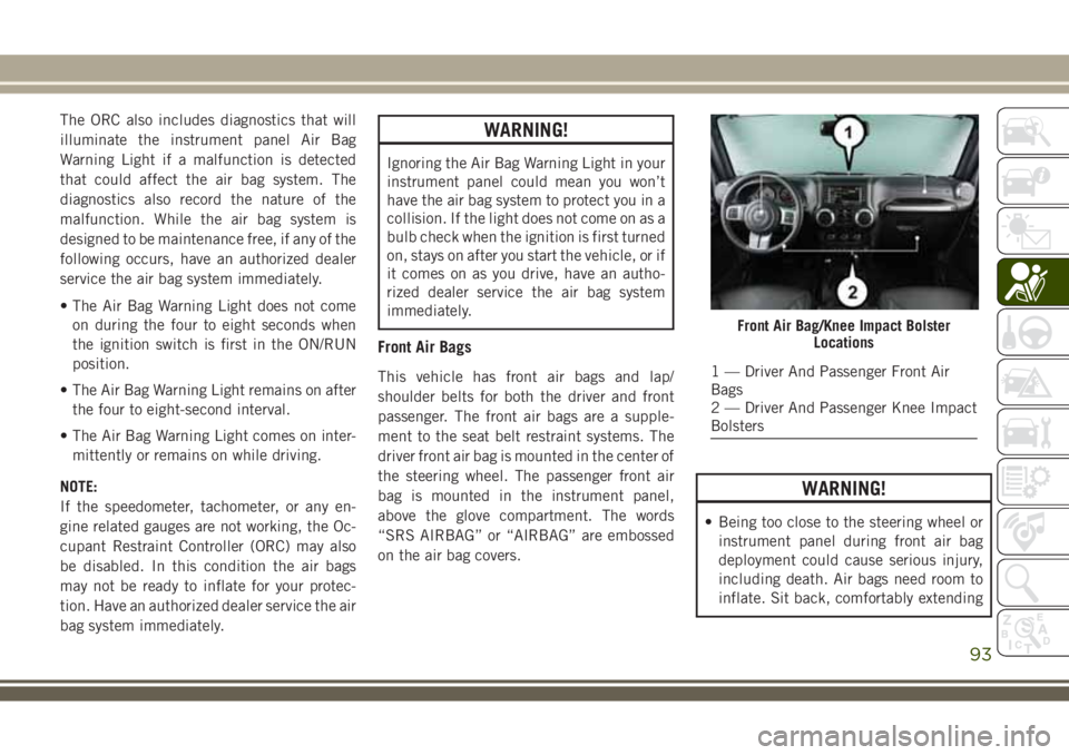
driver front air bag is mounted in the center of
the steering wheel. The passenger front air
bag is mounted in the instrument panel,
above the glove compartment. The words
“SRS AIRBAG” or “AIRBAG” are embossed
on the air bag covers.
WARNING!
• Being too close to the steering wheel or
instrument panel during front air bag
deployment could cause serious injury,
including death. Air bags need room to
inflate. Sit back, comfortably extending
Front Air Bag/Knee Impact Bolster
Locations
1 — Driver And Passenger Front Air
Bags
2 — Driver And Passenger Knee Impact
Bolsters
93
Page 96 of 276
WARNING!
your arms to reach the steering wheel or
instrument panel.
• Never place a rear-facing child restraint
in front of an air bag. A deploying pas-
senger front air bag can cause death or
serious injury to a child 12 years or
younger, including a child in a rear-
facing child restraint.
• Only use a rear-facing child restraint in a
vehicle with a rear seat.
Driver And Passenger Front Air Bag Features
The Advanced Front Air Bag system has mul-
tistage driver and front passenger air bags.
This system provides output appropriate to
the severity and type of collision as deter-
mined by the Occupant Restraint Controller
(ORC), which may receive information from
the front impact sensors (if equipped) or
other system components.
The first stage inflator is triggered immedi-
ately during an impact that requires air bag
deployment. A low energy output is used in
less severe collisions. A higher energy output
is used for more severe collisions.This vehicle may be equipped with a driver
and/or front passenger seat belt buckle
switch that detects whether the driver or front
passenger seat belt is buckled. The seat belt
buckle switch may adjust the inflation rate of
the Advanced Front Air Bags.
WARNING!
• No objects should be placed over or near
the air bag on the instrument panel or
steering wheel because any such objects
could cause harm if the vehicle is in a
collision severe enough to cause the air
bag to inflate.
• Do not put anything on or around the air
bag covers or attempt to open them
manually. You may damage the air bags
and you could be injured because the air
bags may no longer be functional. The
protective covers for the air bag cush-
ions are designed to open only when the
air bags are inflating.
• Relying on the air bags alone could lead
to more severe injuries in a collision. The
air bags work with your seat belt to
restrain you properly. In some collisions,
WARNING!
air bags won’t deploy at all. Always wear
your seat belts even though you have air
bags.
Front Air Bag Operation
Front Air Bags are designed to provide addi-
tional protection by supplementing the seat
belts. Front air bags are not expected to
reduce the risk of injury in rear, side, or
rollover collisions. The front air bags will not
deploy in all frontal collisions, including
some that may produce substantial vehicle
damage — for example, some pole collisions,
truck underrides, and angle offset collisions.
On the other hand, depending on the type
and location of impact, front air bags may
deploy in crashes with little vehicle front-end
damage but that produce a severe initial
deceleration.
Because air bag sensors measure vehicle
deceleration over time, vehicle speed and
damage by themselves are not good indica-
tors of whether or not an air bag should have
deployed.
SAFETY
94
Page 97 of 276
Seat belts are necessary for your protection in
all collisions, and also are needed to help
keep you in position, away from an inflating
air bag.
When the ORC detects a collision requiring
the front air bags, it signals the inflator units.
A large quantity of non-toxic gas is generated
to inflate the front air bags.
The steering wheel hub trim cover and the
upper passenger side of the instrument panel
separate and fold out of the way as the air
bags inflate to their full size. The front air
bags fully inflate in less time than it takes to
blink your eyes. The front air bags then
quickly deflate while helping to restrain the
driver and front passenger.
Knee Impact Bolsters
The Knee Impact Bolsters help protect the
knees of the driver and front passenger, and
position the front occupants for improved
interaction with the front air bags.
WARNING!
• Do not drill, cut, or tamper with the knee
impact bolsters in any way.
• Do not mount any accessories to the
knee impact bolsters such as alarm
lights, stereos, citizen band radios, etc.
Supplemental Side Air Bags
Supplemental Seat-Mounted Side Air Bags
(SABs) (if equipped)
Your vehicle may be equipped with Supple-
mental Seat-Mounted Side Air Bags (SABs).
If your vehicle is equipped with Supplemen-
tal Seat-Mounted Side Air Bags (SABs),
please refer to the information below.
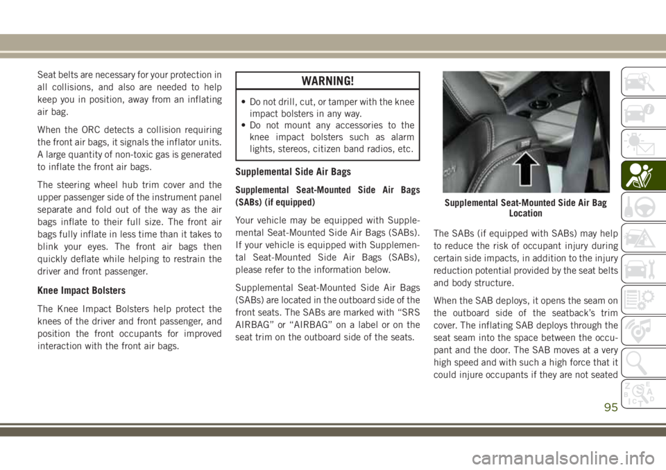
Supplemental Seat-Mounted Side Air Bags
(SABs) are located in the outboard side of the
front seats. The SABs are marked with “SRS
AIRBAG” or “AIRBAG” on a label or on the
seat trim on the outboard side of the seats.The SABs (if equipped with SABs) may help
to reduce the risk of occupant injury during
certain side impacts, in addition to the injury
reduction potential provided by the seat belts
and body structure.
When the SAB deploys, it opens the seam on
the outboard side of the seatback’s trim
cover. The inflating SAB deploys through the
seat seam into the space between the occu-
pant and the door. The SAB moves at a very
high speed and with such a high force that it
could injure occupants if they are not seated
Supplemental Seat-Mounted Side Air Bag
Location
95
Page 99 of 276
WARNING!
some collisions, Side Air Bags won’t
deploy at all. Always wear your seat belt
even though you have Side Air Bags.
NOTE:
Air bag covers may not be obvious in the
interior trim, but they will open during air bag
deployment.
Air Bag System Components
The Occupant Restraint Controller (ORC)
monitors the internal circuits and intercon-
necting wiring associated with electrical Air
Bag System Components listed below:
• Occupant Restraint Controller (ORC)
• Air Bag Warning Light
• Steering Wheel and Column
• Instrument Panel
• Knee Impact Bolsters
• Driver and Front Passenger Air Bags
• Seat Belt Buckle Switch
• Supplemental Side Air Bags• Front and Side Impact Sensors
• Seat Belt Pretensioners
If A Deployment Occurs
The front air bags are designed to deflate
immediately after deployment.
NOTE:
Front and/or side air bags will not deploy in all
collisions. This does not mean something is
wrong with the air bag system.
If you do have a collision which deploys the
air bags, any or all of the following may occur:
• The air bag material may sometimes cause
abrasions and/or skin reddening to the oc-
cupants as the air bags deploy and unfold.
The abrasions are similar to friction rope
burns or those you might get sliding along a
carpet or gymnasium floor. They are not
caused by contact with chemicals. They are
not permanent and normally heal quickly.
However, if you haven’t healed significantly
within a few days, or if you have any blis-
tering, see your doctor immediately.
• As the air bags deflate, you may see some
smoke-like particles. The particles are a
normal by-product of the process that gen-erates the non-toxic gas used for air bag
inflation. These airborne particles may irri-
tate the skin, eyes, nose, or throat. If you
have skin or eye irritation, rinse the area
with cool water. For nose or throat irritation,
move to fresh air. If the irritation continues,
see your doctor. If these particles settle on
your clothing, follow the garment manufac-
turer’s instructions for cleaning.
Do not drive your vehicle after the air bags
have deployed. If you are involved in another
collision, the air bags will not be in place to
protect you.
WARNING!
Deployed air bags and seat belt preten-
sioners cannot protect you in another col-
lision. Have the air bags, seat belt preten-
sioners, and the seat belt retractor
assemblies replaced by an authorized
dealer immediately. Also, have the Occu-
pant Restraint Controller System serviced
as well.
97
Page 100 of 276
NOTE:
• Air bag covers may not be obvious in the
interior trim, but they will open during air
bag deployment.
• After any collision, the vehicle should be
taken to an authorized dealer immediately.
Enhanced Accident Response System
In the event of an impact, if the communica-
tion network remains intact, and the power
remains intact, depending on the nature of
the event, the ORC will determine whether to
have the Enhanced Accident Response Sys-
tem perform the following functions:
• Cut off fuel to the engine.
• Flash hazard lights as long as the battery
has power or until the hazard light button is
pressed. The hazard lights can be deacti-
vated by pressing the hazard light button.
• Turn on the interior lights, which remain on
as long as the battery has power.
• Unlock the power door locks.
Enhanced Accident Response System Reset
Procedure
In order to reset the Enhanced Accident Re-
sponse System functions after an event, the
ignition switch must be changed from igni-
tion START or ON/RUN to ignition OFF. Care-
fully check the vehicle for fuel leaks in the
engine compartment and on the ground near
the engine compartment and fuel tank before
resetting the system and starting the engine.
Maintaining Your Air Bag System
WARNING!
• Modifications to any part of the air bag
system could cause it to fail when you
need it. You could be injured if the air
bag system is not there to protect you.
Do not modify the components or wiring,
including adding any kind of badges or
stickers to the steering wheel hub trim
cover or the upper right side of the
instrument panel. Do not modify the
front bumper, vehicle body structure, or
add aftermarket side steps or running
boards.
WARNING!
• It is dangerous to try to repair any part of
the air bag system yourself. Be sure to
tell anyone who works on your vehicle
that it has an air bag system.
• Do not attempt to modify any part of your
air bag system. The air bag may inflate
accidentally or may not function prop-
erly if modifications are made. Take your
vehicle to an authorized dealer for any
air bag system service. If your seat, in-
cluding your trim cover and cushion,
needs to be serviced in any way (includ-
ing removal or loosening/tightening of
seat attachment bolts), take the vehicle
to your authorized dealer. Only manufac-
turer approved seat accessories may be
used. If it is necessary to modify the air
bag system for persons with disabilities,
contact your authorized dealer.
Event Data Recorder (EDR)
This vehicle is equipped with an event data
recorder (EDR). The main purpose of an EDR
is to record, in certain crash or near crash-
like situations, such as an air bag deployment
SAFETY
98
Page 116 of 276
WARNING!
• ONLY use the driver’s side floor mat on
the driver’s side floor area. To check for
interference, with the vehicle properly
parked with the engine off, fully depress
the accelerator, the brake, and the
clutch pedal (if present) to check for
interference. If your floor mat interferes
with the operation of any pedal, or is not
secure to the floor, remove the floor mat
from the vehicle and place the floor mat
in your trunk.
• ONLY use the passenger’s side floor mat
on the passenger’s side floor area.
• ALWAYS make sure objects cannot fall or
slide into the driver’s side floor area
when the vehicle is moving. Objects can
become trapped under accelerator,
brake, or clutch pedals and could cause
a loss of vehicle control.
• NEVER place any objects under the floor
mat (e.g., towels, keys, etc.). These ob-
jects could change the position of the
floor mat and may cause interference
WARNING!
with the accelerator, brake, or clutch
pedals.
• If the vehicle carpet has been removed
and re-installed, always properly attach
carpet to the floor and check the floor
mat fasteners are secure to the vehicle
carpet. Fully depress each pedal to
check for interference with the accelera-
tor, brake, or clutch pedals then re-
install the floor mats.
• It is recommended to only use mild soap
and water to clean your floor mats. After
cleaning, always check your floor mat
has been properly installed and is se-
cured to your vehicle using the floor mat
fasteners by lightly pulling mat.
Periodic Safety Checks You Should Make
Outside The Vehicle
Tires
Examine tires for excessive tread wear and
uneven wear patterns. Check for stones,
nails, glass, or other objects lodged in thetread or sidewall. Inspect the tread for cuts
and cracks. Inspect sidewalls for cuts,
cracks, and bulges. Check the wheel nuts for
tightness. Check the tires (including spare)
for proper cold inflation pressure.
Lights
Have someone observe the operation of brake
lights and exterior lights while you work the
controls. Check turn signal and high beam
indicator lights on the instrument panel.
Door Latches
Check for proper closing, latching, and lock-
ing.
Fluid Leaks
Check area under vehicle after overnight
parking for fuel, coolant, oil, or other fluid
leaks. Also, if gasoline fumes are detected or
if fuel, or brake fluid leaks are suspected. The
cause should be located and corrected imme-
diately.
SAFETY
114
Page 121 of 276
After Starting
The idle speed is controlled automatically,
and it will decrease as the engine warms up.
Normal Starting — Diesel Engine
1. The gear selector must be in the NEU-
TRAL or PARK position before you can
start the engine.
2. Turn the ignition key to the ON position.
3. Watch for the “Wait To Start Light” in the
instrument cluster. Refer to “Instrument
Cluster” in “Getting To Know Your Instru-
ment Panel” for further review. It will glow
for two to ten seconds or more, depending
on engine temperature. When the “Wait
To Start Light” goes out, the engine is
ready to start.
4. Tip Start Feature (Automatic Transmission
Only)
Do notpress the accelerator. Turn the
ignition key to the START position and
then release it. The starter motor will
continue to run, and it will automatically
disengage when the engine is running. If
the engine fails to start, the starter willdisengage automatically in 25 seconds.
If this occurs, turn the ignition switch to
the LOCK position, wait 25 to 30 sec-
onds, then repeat the “Normal Starting”
procedure.
NOTE:
The starter motor may run up to 30 sec-
onds in very cold conditions until the
engine is started. The starter can be dis-
engaged by turning the ignition key to
the OFF position, if required.
5. Without Tip Start Feature (Manual Trans-
mission Only)
Turn the ignition switch to the START
position and release when the engine
starts. If the engine fails to start within
10 seconds, turn the ignition switch to
the LOCK position, wait 10 to 15 sec-
onds, then repeat the “Normal Starting”
procedure.
6. After the engine starts, allow it to idle for
approximately 30 seconds before driving.
This allows oil to circulate and lubricate
the turbocharger.
Diesel Engine Warm-Up
Avoid full throttle operation when the engine
is cold. When starting a cold engine, bring the
engine up to operating speed slowly to allow
the oil pressure to stabilize as the engine
warms up.
NOTE:
High-speed, no-load running of a cold engine
can result in excessive white smoke and poor
engine performance. No-load engine speeds
should be kept under 1,200 rpm during the
warm-up period, especially in cold, ambient
temperature conditions.
If temperatures are below 32°F (0°C), oper-
ate the engine at moderate speeds for five
minutes before full loads are applied.
Diesel Engine Idling — In Cold Weather
Avoid prolonged idling in ambient tempera-
tures below 0°F (-18°C). Long periods of
idling may be harmful to your engine because
combustion chamber temperatures can drop
so low that the fuel may not burn completely.
Incomplete combustion allows carbon and
varnish to form on piston rings and injector
119
Page 134 of 276
NOTE:
Shifting into or out of 4L is possible with the
vehicle completely stopped; however, diffi-
culty may occur due to the mating teeth not
being properly aligned. Several attempts may
be required for clutch teeth alignment and
shift completion to occur. The preferred
method is with the vehicle rolling at 2 to
3 mph (3 to 5 km/h). Avoid attempting to
engage or disengage 4L with the vehicle
moving faster than 2 to 3 mph (3 to 5 km/h).
WARNING!
Failure to engage a transfer case position
completely can cause transfer case dam-
age or loss of power and vehicle control.
You could have a collision. Do not drive the
vehicle unless the transfer case is fully
engaged.
Trac-Lok Rear Axle — If Equipped
The Trac-Lok rear axle provides a constant
driving force to both rear wheels and reduces
wheel spin caused by the loss of traction at
one driving wheel. If traction differs between
the two rear wheels, the differential auto-
matically proportions the usable torque by
providing more torque to the wheel that has
traction.
Trac-Lok is especially helpful during slippery
driving conditions. With both rear wheels on a
slippery surface, a slight application of the
accelerator will supply maximum traction.
WARNING!
On vehicles equipped with a limited-slip
differential, never run the engine with one
rear wheel off the ground. The vehicle may
drive through the rear wheel remaining on
the ground and cause you to lose control of
your vehicle.
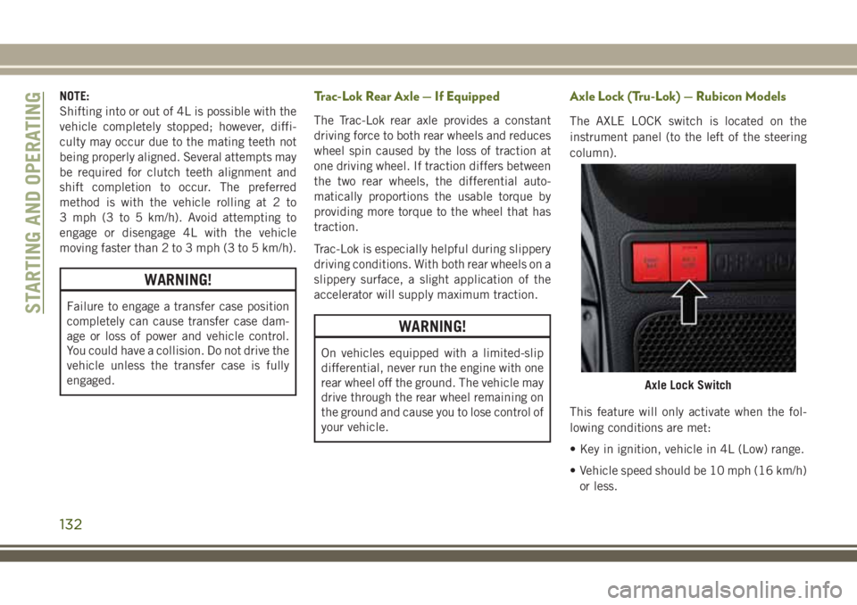
Axle Lock (Tru-Lok) — Rubicon Models
The AXLE LOCK switch is located on the
instrument panel (to the left of the steering
column).
This feature will only activate when the fol-
lowing conditions are met:
• Key in ignition, vehicle in 4L (Low) range.
• Vehicle speed should be 10 mph (16 km/h)
or less.
Axle Lock Switch
STARTING AND OPERATING
132
Page 135 of 276
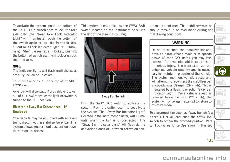
To activate the system, push the bottom of
the AXLE LOCK switch once to lock the rear
axle only (the “Rear Axle Lock Indicator
Light” will illuminate), push the bottom of
the switch again to lock the front axle (the
“Front Axle Lock Indicator Light” will illumi-
nate). When the rear axle is locked, pushing
the bottom of switch again will lock or unlock
the front axle.
NOTE:
The indicator lights will flash until the axles
are fully locked or unlocked.
To unlock the axles, push the top of the AXLE
LOCK switch.
Axle lock will disengage if the vehicle is taken
out of 4L (Low) range, or the ignition switch is
turned to the OFF position.
Electronic Sway Bar Disconnect — If
Equipped
Your vehicle may be equipped with an elec-
tronic disconnecting stabilizer/sway bar. This
system allows greater front suspension travel
in off-road situations.This system is controlled by the SWAY BAR
switch located on the instrument panel (to
the left of the steering column).
Push the SWAY BAR switch to activate the
system. Push the switch again to deactivate
the system. The “Sway Bar Indicator Light”
(located in the instrument cluster) will illumi-
nate when the bar is disconnected. The
“Sway Bar Indicator Light” will flash during
activation transition, or when activation con-ditions are not met. The stabilizer/sway bar
should remain in on-road mode during nor-
mal driving conditions.
WARNING!
Do not disconnect the stabilizer bar and
drive on hardsurfaced roads or at speeds
above 18 mph (29 km/h); you may lose
control of the vehicle, which could result
in serious injury. The front stabilizer bar
enhances vehicle stability and is neces-
sary for maintaining control of the vehicle.
The system monitors vehicle speed and
will attempt to reconnect the stabilizer bar
at speeds over 18 mph (29 km/h). This is
indicated by a flashing or solid “Sway Bar
Indicator Light.” Once vehicle speed is
reduced below 14 mph (22 km/h), the
system will once again attempt to return to
off-road mode.
To disconnect the stabilizer/sway bar, shift to
either 4H or 4L and push the SWAY BAR
switch to obtain the off-road position. Refer
to “Four-Wheel Drive Operation” in this sec-
Sway Bar Switch
133
Page 136 of 276
tion for further information. The “Sway Bar
Indicator Light” will flash until the stabilizer/
sway bar has been fully disconnected.
NOTE:
The stabilizer/sway bar may be torque locked
due to left and right suspension height differ-
ences. This condition is due to driving sur-
face differences or vehicle loading. In order
for the stabilizer/sway bar to disconnect/
reconnect, the right and left halves of the bar
must be aligned. This alignment may require
that the vehicle be driven onto level ground or
rocked from side to side.
To return to on-road mode, push the SWAY
BAR switch again.
WARNING!
If the stabilizer/sway bar will not return to
on-road mode, the “Sway Bar Indicator
Light” will flash in the instrument cluster
and vehicle stability is greatly reduced. Do
not attempt to drive the vehicle over
18 mph (29 km/h). Driving faster than
18 mph (29 km/ h) may cause loss of
control of the vehicle, which could result
WARNING!
in serious injury. Contact your local autho-
rized dealer for assistance.
STOP/START SYSTEM —
DIESEL MODELS WITH
MANUAL TRANSMISSION
ONLY
The Stop/Start function is developed to save
fuel and reduce emissions. The system will
stop the engine automatically during a ve-
hicle stop if the required conditions are met.
Pressing the clutch pedal will automatically
restart the vehicle.
Automatic Mode
The Stop/Start feature is en-
abled after every normal cus-
tomer engine start. It will remain
in STOP/START NOT READY un-
til you drive forward with a ve-
hicle speed greater than 3 mph (5 km/h). Atthat time, the system will go into STOP/
START READY and if all other conditions are
met, can go into an STOP/START AUTO STOP
ACTIVE mode.
To Activate The STOP/START AUTO STOP ACTIVE
Mode, The Following Must Occur:
• The system must be in STOP/START
READY state. A STOP/START READY mes-
sage will be displayed in the instrument
cluster. Refer to “Instrument Cluster Dis-
play” in “Getting To Know Your Instrument
Panel” for further information.
• Vehicle speed must be less 3 mph (5 km/h).
• The gear selector must be in the NEUTRAL
position and the clutch pedal must be fully
released
The engine will shut down,the tachometer will
fall to the Stop/Start position,the STOP/START
AUTO STOP ACTIVE message will appear,
and the heater/air conditioning (HVAC) air
flow will be reduced.
STARTING AND OPERATING
134