steering wheel JEEP WRANGLER 2020 Owner handbook (in English)
[x] Cancel search | Manufacturer: JEEP, Model Year: 2020, Model line: WRANGLER, Model: JEEP WRANGLER 2020Pages: 276, PDF Size: 4.47 MB
Page 5 of 276
Congratulations on selecting your new FCA
US LLC vehicle. Be assured that it represents
precision workmanship, distinctive styling,
and high quality.
ALWAYS drive safely and pay attention to the
road. ALWAYS drive safely with your hands on
the steering wheel. You have full responsibil-
ity and assume all risks related to the use of
the features and applications in this vehicle.
Only use the features and applications when
it is safe to do so. Failure to do so may result
in an accident involving serious injury or
death.
This guide illustrates and describes the op-
eration of features and equipment that are
either standard or optional on this vehicle.
This guide may also include a description of
features and equipment that are no longer
available or were not ordered on this vehicle.
Please disregard any features and equipment
described in this guide that are not available
on this vehicle. FCA US LLC reserves the
right to make changes in design and specifi-
cations and/or make additions to or improve-ments to its products without imposing any
obligation upon itself to install them on prod-
ucts previously manufactured.
This User Guide has been prepared to help
you quickly become acquainted with the im-
portant features of your vehicle. It contains
most things you will need to operate and
maintain the vehicle, including emergency
information.
When it comes to service, remember that your
authorized dealer knows your Jeep
®vehicle
best, has factory-trained technicians and
genuine MOPAR
®parts, and cares about your
satisfaction.
HOW TO FIND YOUR
OWNER’S MANUAL ONLINE
This publication has been prepared as a ref-
erence item to help you quickly become ac-
quainted with the most important features
and processes of your vehicle. It contains
most things you will need to operate and
maintain the vehicle, including emergency
information and procedures.This User Guide is not a replacement for the full
Owner’s Manual, and does not fully cover every
operation and procedure possible with your ve-
hicle.
For more detailed descriptions of the topics
discussed in this User Guide, as well as
information covering features and processes
not covered in this User Guide, the full ve-
hicle Owner’s Manual can be accessed for
free online in a printer-friendly PDF format.
To get the full Owner’s Manual or applicable
supplement for your vehicle, follow the appro-
priate web address below:
www.mopar.eu/owner
FCA US LLC is committed to protecting our
environment and natural resources. By con-
verting from paper to electronic delivery for
the majority of the user information for your
vehicle, together we greatly reduce the de-
mand for tree-based products and lessen the
stress on our environment.
WELCOME FROM FCA US LLC
3
Page 13 of 276
GETTING TO KNOW YOUR VEHICLE
KEYFOB...................13
KeyFob.....................13
IGNITION SWITCH............13
Ignition Key Removal............13
REMOTE STARTING SYSTEM — IF
EQUIPPED.................14
How To Use Remote Start..........14
Remote Start Abort Message........15
To Enter Remote Start............15
To Exit Remote Start Mode Without Driving
The Vehicle...................16
To Exit Remote Start Mode And Drive The
Vehicle.....................16
SENTRY KEY................16
Replacement Key Fobs...........17
Customer Key Programming........17
VEHICLE SECURITY ALARM — IF
EQUIPPED.................18
Rearming The System............18
To Arm The System.............18
To Disarm The System............18
DOORS....................19
Upper Half Door Window Removal — If
Equipped....................19
Front Door Removal..............19
Rear Door Removal (Four-Door Models) . .20
SEATS ....................21
Heated Seats — If Equipped........21
60/40 Split Folding Rear Seat —
Four Door Models..............22
Front Passenger Easy Entry Seat —
Two Door Models...............23
Tip ‘n Slide Seats — Two Door Models . .24
Removing The Rear Seat — Two Door
Models.....................24
HEAD RESTRAINTS...........25
Front Head Restraints............25
Rear Head Restraints — 2 Door Model . .26
Rear Head Restraints — 4 Door Model . .27
STEERING WHEEL............28
Tilt Steering Column.............28
MIRRORS..................28
Heated Mirrors — If Equipped.......28
EXTERIOR LIGHTS............28
Headlights And Parking Lights.......28
Daytime Running Lights — If Equipped .29
High/Low Beam Switch...........29
Flash-To-Pass.................29
Automatic Headlights — If Equipped . .29
Front Fog Lights...............29
Rear Fog Lights — If Equipped......29
Turn Signals..................29
Lane Change Assist — If Equipped....30
Lights-On Reminder.............30
Headlight Leveling System — If
Equipped...................30
WINDSHIELD WIPERS AND WASH-
ERS ......................30
Windshield Wiper Operation.........31
Rear Window Wiper/Washer — If
Equipped...................32
GETTING TO KNOW YOUR VEHICLE
11
Page 30 of 276
STEERING WHEEL
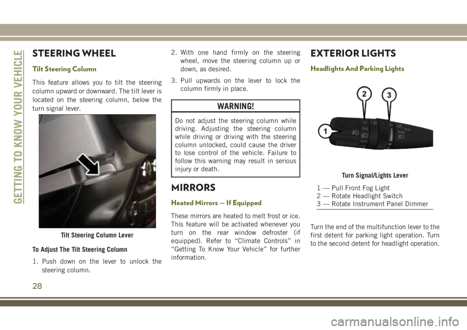
Tilt Steering Column
This feature allows you to tilt the steering
column upward or downward. The tilt lever is
located on the steering column, below the
turn signal lever.
To Adjust The Tilt Steering Column
1. Push down on the lever to unlock the
steering column.2. With one hand firmly on the steering
wheel, move the steering column up or
down, as desired.
3. Pull upwards on the lever to lock the
column firmly in place.
WARNING!
Do not adjust the steering column while
driving. Adjusting the steering column
while driving or driving with the steering
column unlocked, could cause the driver
to lose control of the vehicle. Failure to
follow this warning may result in serious
injury or death.
MIRRORS
Heated Mirrors — If Equipped
These mirrors are heated to melt frost or ice.
This feature will be activated whenever you
turn on the rear window defroster (if
equipped). Refer to “Climate Controls” in
“Getting To Know Your Vehicle” for further
information.
EXTERIOR LIGHTS
Headlights And Parking Lights
Turn the end of the multifunction lever to the
first detent for parking light operation. Turn
to the second detent for headlight operation.
Tilt Steering Column Lever
Turn Signal/Lights Lever
1 — Pull Front Fog Light
2 — Rotate Headlight Switch
3 — Rotate Instrument Panel Dimmer
GETTING TO KNOW YOUR VEHICLE
28
Page 31 of 276
Daytime Running Lights — If Equipped
The headlights come on at a low intensity level
when shifted into any position other than PARK
(auto transmission) or when the vehicle begins
to move (manual transmission).
NOTE:
The Daytime Running Light, on the same side
of the vehicle as the active turn signal, will
turn off automatically when a turn signal is in
operation and turn on again when the turn
signal is not operating.
High/Low Beam Switch
Push the multifunction lever toward the in-
strument panel to switch the headlights to
high beams. Pulling the multifunction lever
back toward the steering wheel will return the
lights to low beams.
Flash-To-Pass
You can signal another vehicle with your
headlights by lightly pulling the multifunc-
tion lever toward you. This will cause the high
beam headlights to turn on, and remain on,
until the lever is released.
Automatic Headlights — If Equipped
This system automatically turns the head-
lights on or off according to ambient light
levels. To turn the system on, turn the end of
the multifunction lever to the AUTO position
(third detent). When the system is on, the
Headlight Time Delay feature is also on. This
means the headlights will stay on for up to
90 seconds after you turn the ignition switch
to the LOCK position. To turn the Automatic
System off, turn the end of the multifunction
lever out of the AUTO position.
NOTE:
The engine must be running before the head-
lights will turn on in the Automatic mode.
Front Fog Lights
The front fog light switch is located on the
multifunction lever. To activate the front fog
lights, turn on the parking or low beam head-
lights and pull out the end of the lever.NOTE:
The fog lights will only operate with the park-
ing lights or the headlights on low beam.
Selecting high beam headlights will turn off
the fog lights.
Rear Fog Lights — If Equipped
The rear fog lights may be operated, as de-
sired, when visibility is poor due to fog. To
activate the rear fog lights, turn on the low
beam, high beam, or front fog lamps, pull out
the end of the multifunction lever and rotate
the lever to the last detent.
Turn Signals
Move the multifunction lever up or down and
the arrows on each side of the instrument
cluster flash to show proper operation of the
front and rear turn signal lights.
29
Page 58 of 276
INSTRUMENT CLUSTER
DISPLAY — IF EQUIPPED
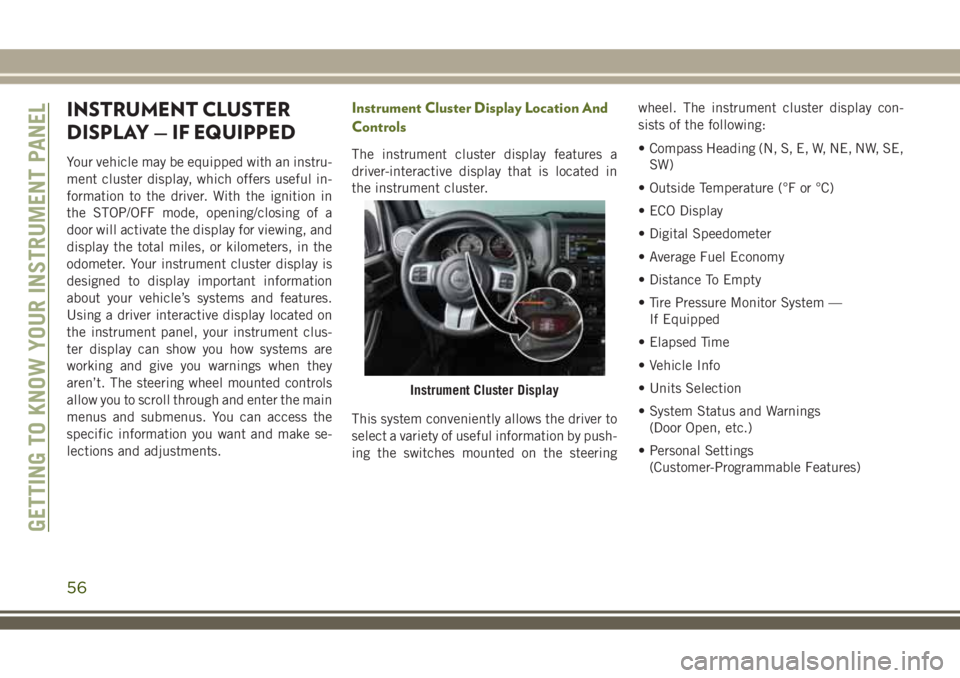
Your vehicle may be equipped with an instru-
ment cluster display, which offers useful in-
formation to the driver. With the ignition in
the STOP/OFF mode, opening/closing of a
door will activate the display for viewing, and
display the total miles, or kilometers, in the
odometer. Your instrument cluster display is
designed to display important information
about your vehicle’s systems and features.
Using a driver interactive display located on
the instrument panel, your instrument clus-
ter display can show you how systems are
working and give you warnings when they
aren’t. The steering wheel mounted controls
allow you to scroll through and enter the main
menus and submenus. You can access the
specific information you want and make se-
lections and adjustments.
Instrument Cluster Display Location And
Controls
The instrument cluster display features a
driver-interactive display that is located in
the instrument cluster.
This system conveniently allows the driver to
select a variety of useful information by push-
ing the switches mounted on the steeringwheel. The instrument cluster display con-
sists of the following:
• Compass Heading (N, S, E, W, NE, NW, SE,
SW)
• Outside Temperature (°F or °C)
• ECO Display
• Digital Speedometer
• Average Fuel Economy
• Distance To Empty
• Tire Pressure Monitor System —
If Equipped
• Elapsed Time
• Vehicle Info
• Units Selection
• System Status and Warnings
(Door Open, etc.)
• Personal Settings
(Customer-Programmable Features)
Instrument Cluster Display
GETTING TO KNOW YOUR INSTRUMENT PANEL
56
Page 59 of 276
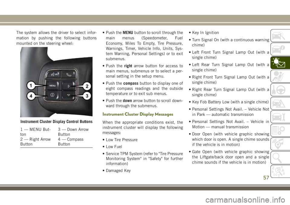
The system allows the driver to select infor-
mation by pushing the following buttons
mounted on the steering wheel:• Push theMENUbutton to scroll through the
main menus (Speedometer, Fuel
Economy, Miles To Empty, Tire Pressure,
Warnings, Timer, Vehicle Info, Units, Sys-
tem Warning, Personal Settings) or to exit
submenus.
• Push therightarrow button for access to
main menus, submenus or to select a per-
sonal setting in the setup menu.
• Push thecompassbutton to display one of
eight compass readings and the outside
temperature or to exit sub menus.
• Push thedownarrow button to scroll down-
ward through the submenus.
Instrument Cluster Display Messages
When the appropriate conditions exist, the
instrument cluster will display the following
messages:
• Low Tire Pressure
• Low Fuel
• Service TPM System (refer to "Tire Pressure
Monitoring System" in "Safety" for further
information)
• Damaged Key• Key In Ignition
• Turn Signal On (with a continuous warning
chime)
• Left Front Turn Signal Lamp Out (with a
single chime)
• Left Rear Turn Signal Lamp Out (with a
single chime)
• Right Front Turn Signal Lamp Out (with a
single chime)
• Right Rear Turn Signal Lamp Out (with a
single chime)
• Key Fob Battery Low (with a single chime)
• Personal Settings Not Avail. – Vehicle Not
in Park — automatic transmission
• Personal Settings Not Avail. – Vehicle in
Motion — manual transmission
• Door Open (with vehicle graphic showing
which door is open. A single chime sounds
if the vehicle is in motion)
• Gate Open (with vehicle graphic showing
the Liftgate/back door open and a single
chime sounds if the vehicle is in motion)Instrument Cluster Display Control Buttons
1 — MENU But-
ton3 — Down Arrow
Button
2 — Right Arrow
Button4 — Compass
Button
57
Page 70 of 276
SAFETY FEATURES
Anti-Lock Brake System (ABS)
The Anti-Lock Brake System (ABS) provides
increased vehicle stability and brake perfor-
mance under most braking conditions. The
system automatically prevents wheel lock,
and enhances vehicle control during braking.
The ABS performs a self-check cycle to en-
sure that the ABS is working properly each
time the vehicle is started and driven. During
this self-check, you may hear a slight clicking
sound as well as some related motor noises.
ABS is activated during braking when the
system detects one or more wheels begin to
lock. Road conditions such as ice, snow,
gravel, bumps, railroad tracks, loose debris,
or panic stops may increase the likelihood of
ABS activation(s).
You also may experience the following when
ABS activates:
• The ABS motor noise (it may continue to
run for a short time after the stop).
• The clicking sound of solenoid valves.• Brake pedal pulsations.
• A slight drop of the brake pedal at the end
of the stop.
These are all normal characteristics of ABS.
WARNING!
• The ABS contains sophisticated elec-
tronic equipment that may be suscep-
tible to interference caused by improp-
erly installed or high output radio
transmitting equipment. This interfer-
ence can cause possible loss of anti-lock
braking capability. Installation of such
equipment should be performed by
qualified professionals.
• Pumping of the Anti-Lock Brakes will
diminish their effectiveness and may
lead to a collision. Pumping makes the
stopping distance longer. Just press
firmly on your brake pedal when you
need to slow down or stop.
• The ABS cannot prevent the natural laws
of physics from acting on the vehicle,
nor can it increase braking or steering
efficiency beyond that afforded by the
WARNING!
condition of the vehicle brakes and tires
or the traction afforded.
• The ABS cannot prevent collisions, in-
cluding those resulting from excessive
speed in turns, following another vehicle
too closely, or hydroplaning.
• The capabilities of an ABS equipped
vehicle must never be exploited in a
reckless or dangerous manner that could
jeopardize the user’s safety or the safety
of others.
ABS is designed to function with the OEM
tires. Modification may result in degraded
ABS performance.
Anti-Lock Brake Warning Light
The yellow “Anti-Lock Brake Warning Light”
will turn on when the ignition is turned to the
ON/RUN mode and may stay on for as long as
four seconds.
If the “Anti-Lock Brake Warning Light” re-
mains on or comes on while driving, it indi-
cates that the anti-lock portion of the brake
system is not functioning and that service is
SAFETY
68
Page 72 of 276
WARNING!
speed in turns, driving on very slippery
surfaces, or hydroplaning. The capabilities
of a BAS-equipped vehicle must never be
exploited in a reckless or dangerous man-
ner, which could jeopardize the user's
safety or the safety of others.
Hill Start Assist (HSA)
The HSA system is designed to mitigate roll
back from a complete stop while on an in-
cline. If the driver releases the brake while
stopped on an incline, HSA will continue to
hold the brake pressure for a short period. If
the driver does not apply the throttle before
this time expires, the system will release
brake pressure and the vehicle will roll down
the hill as normal.
The following conditions must be met in
order for HSA to activate:
• The feature must be enabled.
• The vehicle must be stopped.
• Park brake must be off.• Driver door must be closed.
• The vehicle must be on a sufficient grade.
• The gear selection must match vehicle up-
hill direction (i.e., vehicle facing uphill is in
forward gear; vehicle backing uphill is in
REVERSE gear).
• HSA will work in REVERSE gear and all
forward gears. The system will not activate
if the transmission is in PARK or NEU-
TRAL. For vehicles equipped with a manual
transmission, if the clutch is pressed, HSA
will remain active.
WARNING!
There may be situations where the Hill
Start Assist (HSA) will not activate and
slight rolling may occur, such as on minor
hills or with a loaded vehicle, or while
pulling a trailer. HSA is not a substitute for
active driving involvement. It is always the
driver’s responsibility to be attentive to
distance to other vehicles, people, and
objects, and most importantly brake op-
eration to ensure safe operation of the
vehicle under all road conditions. Your
WARNING!
complete attention is always required
while driving to maintain safe control of
your vehicle. Failure to follow these warn-
ings can result in a collision or serious
personal injury.
Disabling And Enabling HSA
This feature can be turned on or turned off.
To change the current setting using your
instrument cluster display, refer to “Instru-
ment Cluster Display” in “Getting To Know
Your Instrument Panel” for further informa-
tion.
For vehicles not equipped with an instrument
cluster display, perform the following steps:
1. Center the steering wheel (front wheels
pointing straight forward).
2. Shift the transmission into PARK.
3. Apply the parking brake.
4. Start the engine.
5. Rotate the steering wheel slightly more
than one-half turn to the left.
SAFETY
70
Page 73 of 276
6. Push the “ESC Off” button located in the
lower switch bank below the climate con-
trol four times within 20 seconds. The
“ESC Off Indicator Light” should turn on
and turn off two times.
7. Rotate the steering wheel back to center
and then an additional slightly more than
one-half turn to the right.
8. Turn the ignition to the OFF mode and
then back to ON. If the sequence was
completed properly, the “ESC Off Indica-
tor Light” will blink several times to con-
firm HSA is disabled.
9. Repeat these steps if you want to return
this feature to its previous setting.
Traction Control System (TCS)
This system monitors the amount of wheel
spin of each of the driven wheels. If wheel
spin is detected, the TCS may apply brake
pressure to the spinning wheel(s) and/or re-
duce engine power to provide enhanced ac-
celeration and stability. A feature of the TCS,
Brake Limited Differential (BLD), functions
similar to a limited slip differential and con-
trols the wheel spin across a driven axle. Ifone wheel on a driven axle is spinning faster
than the other, the system will apply the
brake of the spinning wheel. This will allow
more engine torque to be applied to the wheel
that is not spinning. BLD may remain en-
abled even if TCS and ESC are in a reduced
mode.
Electronic Stability Control (ESC)
This system enhances directional control and
stability of the vehicle under various driving
conditions. The ESC corrects for over/under
steering of the vehicle by applying the brake
of the appropriate wheel to assist in counter-
acting the over/under steer condition. Engine
power may also be reduced to help the ve-
hicle maintain the desired path.
ESC uses sensors in the vehicle to determine
the vehicle path intended by the driver and
compares it to the actual path of the vehicle.
When the actual path does not match the
intended path, ESC applies the brake of the
appropriate wheel to assist in counteracting
the oversteer or understeer condition.
• Oversteer - when the vehicle is turning more
than appropriate for the steering wheel po-
sition.• Understeer - when the vehicle is turning
less than appropriate for the steering wheel
position.
The “ESC Activation/Malfunction Indicator
Light” (located in the instrument cluster),
starts to flash as soon as the tires lose trac-
tion and the ESC system becomes active. The
“ESC Activation/Malfunction Indicator
Light” also flashes when TCS is active. If the
“ESC Activation/Malfunction Indicator
Light” begins to flash during acceleration,
ease up on the accelerator and apply as little
throttle as possible. Be sure to adapt your
speed and driving to the prevailing road
conditions.
WARNING!
• Electronic Stability Control (ESC) can-
not prevent the natural laws of physics
from acting on the vehicle, nor can it
increase the traction afforded by prevail-
ing road conditions. ESC cannot prevent
accidents, including those resulting
from excessive speed in turns, driving on
very slippery surfaces, or hydroplaning.
71
Page 74 of 276
WARNING!
ESC also cannot prevent accidents re-
sulting from loss of vehicle control due
to inappropriate driver input for the con-
ditions. Only a safe, attentive, and skill-
ful driver can prevent accidents. The
capabilities of an ESC equipped vehicle
must never be exploited in a reckless or
dangerous manner which could jeopar-
dize the user’s safety or the safety of
others.
• Vehicle modifications, or failure to prop-
erly maintain your vehicle, may change
the handling characteristics of your ve-
hicle, and may negatively affect the per-
formance of the ESC system. Changes to
the steering system, suspension, brak-
ing system, tire type and size or wheel
size may adversely affect ESC perfor-
mance. Improperly inflated and un-
evenly worn tires may also degrade ESC
performance. Any vehicle modification
or poor vehicle maintenance that re-
duces the effectiveness of the ESC sys-
tem can increase the risk of loss of
WARNING!
vehicle control, vehicle rollover, per-
sonal injury and death.
The ESC system has three available operating
modes in 4H range. The system has one
operating mode in 4L range. Two-wheel drive
vehicles and four-wheel drive vehicles in 2H
range have two operating modes.
4H Range (4WD Models)
ESC On
This is the normal operating mode for ESC in
4H range.
ESC Partial Off
This mode is entered by momentarily pushing
the ESC OFF switch. When in "ESC Partial
Off" mode, the TCS portion of ESC (except for
the limited slip feature described in the TCS
section), has been disabled and the "ESC Off
Indicator Light" will be illuminated.
This mode is intended to be used if the
vehicle is in deep snow, sand, or gravel con-
ditions and more wheel spin than ESC would
normally allow is required to gain traction. Toturn ESC on again, momentarily push the
ESC OFF switch. This will restore the normal
“ESC On” mode of operation.
NOTE:
To improve the vehicle’s traction when driving
with snow chains, or starting off in deep
snow, sand, or gravel, it may be desirable to
switch to the "ESC Partial Off" mode by
pushing the ESC OFF switch. Once the situ-
ation requiring ESC to be switched to the
"ESC Partial Off" mode is overcome, turn ESC
back on by momentarily pushing the ESC
OFF switch. This may be done while the
vehicle is in motion.
WARNING!
• When in "ESC Partial Off" mode, the TCS
functionality of ESC, (except for the lim-
ited slip feature described in the TCS
section), has been disabled and the
“ESC Off Indicator Light” will be illumi-
nated. When in "ESC Partial Off" mode,
the engine power reduction feature of
TCS is disabled, and the enhanced ve-
SAFETY
72