warning light JEEP WRANGLER 2020 Owner handbook (in English)
[x] Cancel search | Manufacturer: JEEP, Model Year: 2020, Model line: WRANGLER, Model: JEEP WRANGLER 2020Pages: 276, PDF Size: 4.47 MB
Page 17 of 276
• Ignition key removed from ignition
• Battery at an acceptable charge level
• System not disabled from previous remote
start event
• Vehicle security alarm not active
WARNING!
• Do not start or run an engine in a closed
garage or confined area. Exhaust gas
contains Carbon Monoxide (CO) which is
odorless and colorless. Carbon Monox-
ide is poisonous and can cause serious
injury or death when inhaled.
• Keep key fobs away from children. Op-
eration of the Remote Start System, win-
dows, door locks or other controls could
cause serious injury or death.
Remote Start Abort Message
The following messages will display in the
instrument cluster display if the vehicle fails to
remote start or exits remote start prematurely:
• Remote Start Aborted — Door Open
• Remote Start Aborted — Hood Open
• Remote Start Aborted — Fuel Low
• Remote Start Aborted — Swing Gate Open
• Remote Start Aborted — System Fault
The instrument cluster display message stays
active until the ignition is turned to the ON/
RUN position.
To Enter Remote Start
Push and release the remote start button on
the key fob twice within five seconds. The
vehicle doors will lock, the parking lights will
flash and the horn will chirp twice (if pro-
grammed). Then, the engine will start and the
vehicle will remain in the remote start mode
for a 15-minute cycle.NOTE:
• The park lamps will turn on and remain on
during remote start mode.
• For security, power window operation is
disabled when the vehicle is in the remote
start mode.
• The engine can be started two consecutive
times (two 15-minute cycles) with the key
fob. However, the ignition switch must be
cycled to the ON/RUN position before you
can repeat the start sequence for a third
cycle.
Remote start will also cancel if any of the
following occur:
• The engine stalls or RPM exceeds 2500.
• Any engine warning lamps come on.
• The hood is opened.
• The hazard switch is pushed.
• The transmission is moved out of PARK.
• The brake pedal is pushed.
15
Page 24 of 276
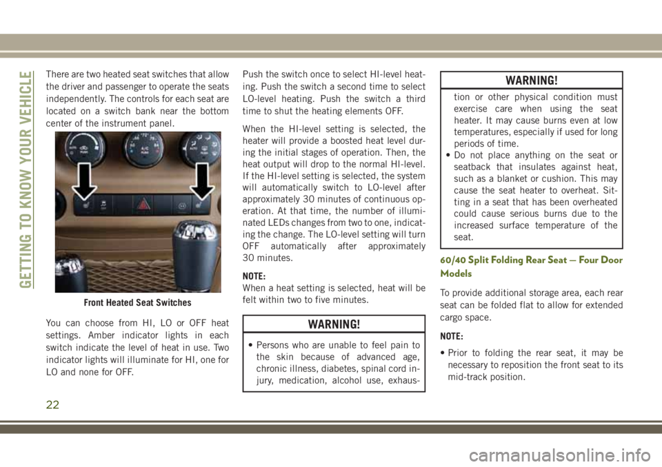
There are two heated seat switches that allow
the driver and passenger to operate the seats
independently. The controls for each seat are
located on a switch bank near the bottom
center of the instrument panel.
You can choose from HI, LO or OFF heat
settings. Amber indicator lights in each
switch indicate the level of heat in use. Two
indicator lights will illuminate for HI, one for
LO and none for OFF.Push the switch once to select HI-level heat-
ing. Push the switch a second time to select
LO-level heating. Push the switch a third
time to shut the heating elements OFF.
When the HI-level setting is selected, the
heater will provide a boosted heat level dur-
ing the initial stages of operation. Then, the
heat output will drop to the normal HI-level.
If the HI-level setting is selected, the system
will automatically switch to LO-level after
approximately 30 minutes of continuous op-
eration. At that time, the number of illumi-
nated LEDs changes from two to one, indicat-
ing the change. The LO-level setting will turn
OFF automatically after approximately
30 minutes.
NOTE:
When a heat setting is selected, heat will be
felt within two to five minutes.
WARNING!
• Persons who are unable to feel pain to
the skin because of advanced age,
chronic illness, diabetes, spinal cord in-
jury, medication, alcohol use, exhaus-
WARNING!
tion or other physical condition must
exercise care when using the seat
heater. It may cause burns even at low
temperatures, especially if used for long
periods of time.
• Do not place anything on the seat or
seatback that insulates against heat,
such as a blanket or cushion. This may
cause the seat heater to overheat. Sit-
ting in a seat that has been overheated
could cause serious burns due to the
increased surface temperature of the
seat.
60/40 Split Folding Rear Seat — Four Door
Models
To provide additional storage area, each rear
seat can be folded flat to allow for extended
cargo space.
NOTE:
• Prior to folding the rear seat, it may be
necessary to reposition the front seat to its
mid-track position.Front Heated Seat Switches
GETTING TO KNOW YOUR VEHICLE
22
Page 30 of 276
STEERING WHEEL
Tilt Steering Column
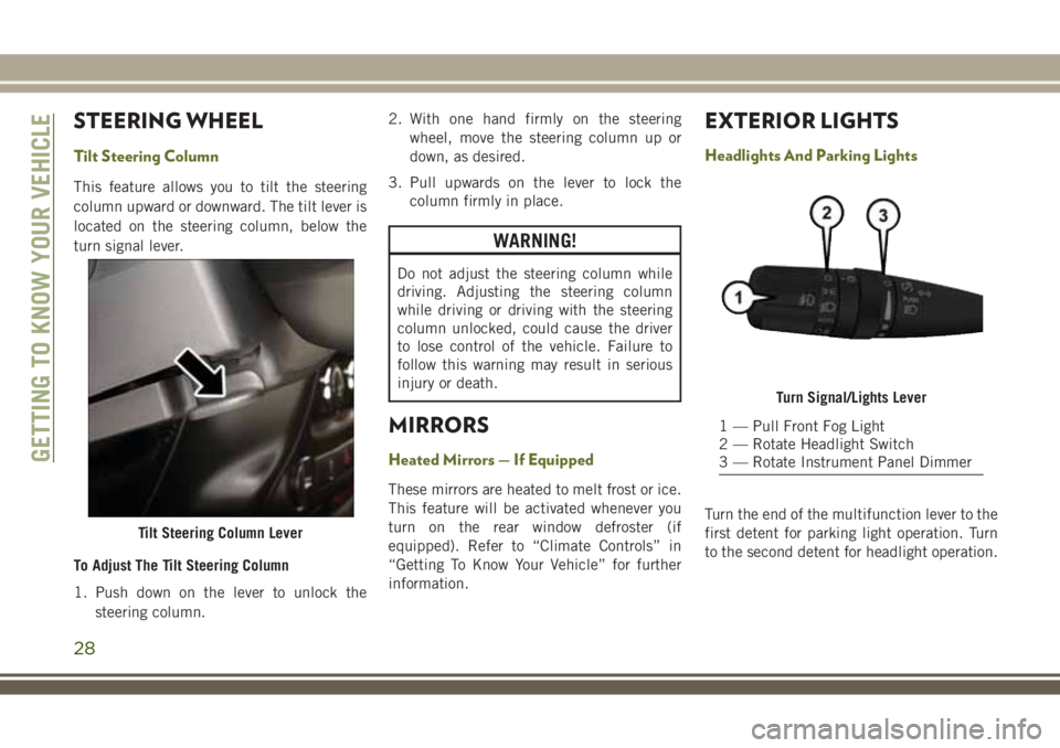
This feature allows you to tilt the steering
column upward or downward. The tilt lever is
located on the steering column, below the
turn signal lever.
To Adjust The Tilt Steering Column
1. Push down on the lever to unlock the
steering column.2. With one hand firmly on the steering
wheel, move the steering column up or
down, as desired.
3. Pull upwards on the lever to lock the
column firmly in place.
WARNING!
Do not adjust the steering column while
driving. Adjusting the steering column
while driving or driving with the steering
column unlocked, could cause the driver
to lose control of the vehicle. Failure to
follow this warning may result in serious
injury or death.
MIRRORS
Heated Mirrors — If Equipped
These mirrors are heated to melt frost or ice.
This feature will be activated whenever you
turn on the rear window defroster (if
equipped). Refer to “Climate Controls” in
“Getting To Know Your Vehicle” for further
information.
EXTERIOR LIGHTS
Headlights And Parking Lights
Turn the end of the multifunction lever to the
first detent for parking light operation. Turn
to the second detent for headlight operation.
Tilt Steering Column Lever
Turn Signal/Lights Lever
1 — Pull Front Fog Light
2 — Rotate Headlight Switch
3 — Rotate Instrument Panel Dimmer
GETTING TO KNOW YOUR VEHICLE
28
Page 53 of 276
Wind Buffeting
Wind buffeting can be described as a
helicopter-type percussion sound. If buffet-
ing occurs with the rear windows open, adjust
the front and rear windows together.
HOOD
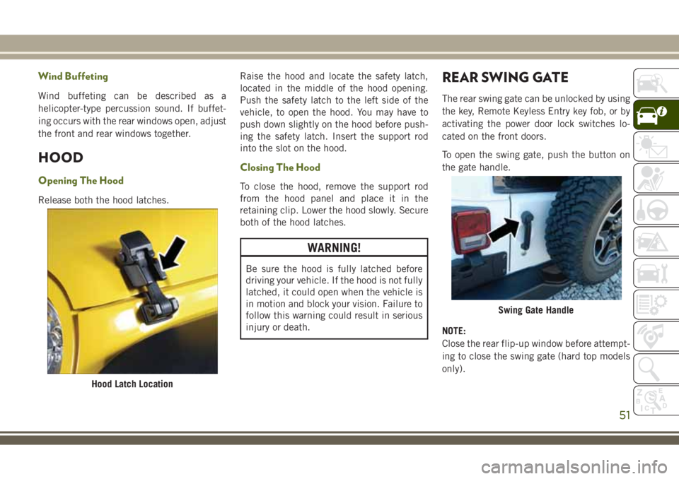
Opening The Hood
Release both the hood latches.Raise the hood and locate the safety latch,
located in the middle of the hood opening.
Push the safety latch to the left side of the
vehicle, to open the hood. You may have to
push down slightly on the hood before push-
ing the safety latch. Insert the support rod
into the slot on the hood.
Closing The Hood
To close the hood, remove the support rod
from the hood panel and place it in the
retaining clip. Lower the hood slowly. Secure
both of the hood latches.
WARNING!
Be sure the hood is fully latched before
driving your vehicle. If the hood is not fully
latched, it could open when the vehicle is
in motion and block your vision. Failure to
follow this warning could result in serious
injury or death.
REAR SWING GATE
The rear swing gate can be unlocked by using
the key, Remote Keyless Entry key fob, or by
activating the power door lock switches lo-
cated on the front doors.
To open the swing gate, push the button on
the gate handle.
NOTE:
Close the rear flip-up window before attempt-
ing to close the swing gate (hard top models
only).
Hood Latch Location
Swing Gate Handle
51
Page 54 of 276
WARNING!
Driving with the flip-up window open can
allow poisonous exhaust gases into your
vehicle. You and your passengers could be
injured by these fumes. Keep the flip-up
window closed when you are operating the
vehicle.
CAUTION!
Do not push on rear wiper blade when
closing the rear flip-up window, as damage
to the blade will result.
INTERNAL EQUIPMENT
Power Outlets
There are three possible 12 Volt Power Out-
lets in this vehicle.
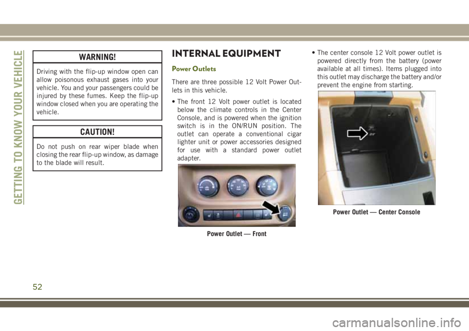
• The front 12 Volt power outlet is located
below the climate controls in the Center
Console, and is powered when the ignition
switch is in the ON/RUN position. The
outlet can operate a conventional cigar
lighter unit or power accessories designed
for use with a standard power outlet
adapter.• The center console 12 Volt power outlet is
powered directly from the battery (power
available at all times). Items plugged into
this outlet may discharge the battery and/or
prevent the engine from starting.
Power Outlet — Front
Power Outlet — Center Console
GETTING TO KNOW YOUR VEHICLE
52
Page 57 of 276
GETTING TO KNOW YOUR INSTRUMENT PANEL
INSTRUMENT CLUSTER DISPLAY —
IF EQUIPPED................56
Instrument Cluster Display Location And
Controls.....................56
Instrument Cluster Display Messages . . .57
Gear Shift Indicator (GSI) — If
Equipped....................58
Oil Change Required.............58
WARNING LIGHTS AND MES-
SAGES ....................58
Red Warning Lights..............58
Yellow Warning Lights............61
Yellow Indicator Lights............63
Green Indicator Lights............64
White Indicator Lights............64
Blue Indicator Lights.............64
ONBOARD DIAGNOSTIC SYSTEM —
OBDII ....................64
Onboard Diagnostic System (OBD II)
Cybersecurity.................65
Loose Fuel Filler Cap Message.......65
GETTING TO KNOW YOUR INSTRUMENT PANEL
55
Page 60 of 276
• Check Gascap (refer to “Refueling The Ve-
hicle” in “Starting And Operating” for fur-
ther information)
• Oil Change Required (with a single chime)
• ECO (Fuel Saver Indicator) — if equipped
Gear Shift Indicator (GSI) — If Equipped
The Gear Shift Indicator (GSI) system is en-
abled on vehicles with a manual transmis-
sion, or when a vehicle with an automatic
transmission is in manual shift mode. The
GSI provides the driver with a visual indica-
tion when the recommended gear shift point
has been reached. This indication notifies
the driver that changing gear will allow a
reduction in fuel consumption. When the up
shift indicator is shown on the display, the
GSI is advising the driver to engage a higher
gear. When the down shift indicator is shown
on the display, the GSI is advising the driver
to engage a lower gear.
The GSI indicator remains illuminated until
the driver changes gear, or the driving condi-
tions return to a situation where changing gear
is not required to improve fuel consumption.
Oil Change Required
Your vehicle is equipped with an engine oil
change indicator system. The “Oil Change
Required” message will display in the instru-
ment cluster display for approximately
10 seconds after a single chime has sounded
to indicate the next scheduled oil change
interval. The engine oil change indicator sys-
tem is duty cycle based, which means the
engine oil change interval may fluctuate de-
pendent upon your personal driving style.
Unless reset, this message will continue to
display each time you turn the ignition switch
to the ON position. To turn off the message
temporarily, push and release theMENUbut-
ton. To reset the oil change indicator system
(after performing the scheduled mainte-
nance), perform the following procedure:
WARNING LIGHTS AND
MESSAGES
The warning/indicator lights will illuminate in
the instrument panel together with a dedi-
cated message and/or acoustic signal when
applicable. These indications are indicativeand precautionary and as such must not be
considered as exhaustive and/or alternative
to the information contained in the Owner’s
Manual, which you are advised to read care-
fully in all cases. Always refer to the informa-
tion in this chapter in the event of a failure
indication. All active telltales will display first
if applicable. The system check menu may
appear different based upon equipment op-
tions and current vehicle status. Some tell-
tales are optional and may not appear.
Red Warning Lights
— Air Bag Warning Light
This light indicates a fault with the air bag,
and will turn on for four to eight seconds as a
bulb check when the ignition is placed in the
ON/RUN or ACC/ON/RUN position. This light
will illuminate with a single chime when a
fault with the air bag has been detected, it
will stay on until the fault is cleared. If the
light is either not on during startup, stays on,
or turns on while driving, have the system
inspected at an authorized dealer as soon as
possible.
GETTING TO KNOW YOUR INSTRUMENT PANEL
58
Page 61 of 276
— Brake Warning Light
This light monitors various brake functions,
including brake fluid level and parking brake
application. If the brake light turns on it may
indicate that the parking brake is applied,
that the brake fluid level is low, or that there
is a problem with the anti-lock brake system.
If the light remains on when the parking
brake has been disengaged, and the fluid
level is at the full mark on the master cylinder
reservoir, it indicates a possible brake hy-
draulic system malfunction or that a problem
with the Brake Booster has been detected by
the Anti-Lock Brake System (ABS) / Elec-
tronic Stability Control (ESC) system. In this
case, the light will remain on until the condi-
tion has been corrected. If the problem is
related to the brake booster, the ABS pump
will run when applying the brake, and a brake
pedal pulsation may be felt during each stop.
The dual brake system provides a reserve
braking capacity in the event of a failure to a
portion of the hydraulic system. A leak in
either half of the dual brake system is indi-cated by the Brake Warning Light, which will
turn on when the brake fluid level in the
master cylinder has dropped below a speci-
fied level.
The light will remain on until the cause is
corrected.
NOTE:
The light may flash momentarily during sharp
cornering maneuvers, which change fluid
level conditions. The vehicle should have
service performed, and the brake fluid level
checked.
If brake failure is indicated, immediate repair
is necessary.
WARNING!
Driving a vehicle with the red brake light
on is dangerous. Part of the brake system
may have failed. It will take longer to stop
the vehicle. You could have a collision.
Have the vehicle checked immediately.Vehicles equipped with the Anti-Lock Brake
System (ABS) are also equipped with Elec-
tronic Brake Force Distribution (EBD). In the
event of an EBD failure, the Brake Warning
Light will turn on along with the ABS Light.
Immediate repair to the ABS system is re-
quired.
Operation of the Brake Warning Light can be
checked by turning the ignition switch from
the OFF position to the ON/RUN position.
The light should illuminate for approximately
four seconds. The light should then turn off
unless the parking brake is applied or a brake
fault is detected. If the light does not illumi-
nate, have the light inspected by an autho-
rized dealer.
The light also will turn on when the parking
brake is applied with the ignition switch in
the ON/RUN position.
NOTE:
This light shows only that the parking brake is
applied. It does not show the degree of brake
application.
59
Page 62 of 276
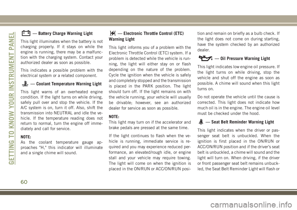
— Battery Charge Warning Light
This light illuminates when the battery is not
charging properly. If it stays on while the
engine is running, there may be a malfunc-
tion with the charging system. Contact your
authorized dealer as soon as possible.
This indicates a possible problem with the
electrical system or a related component.
— Coolant Temperature Warning Light
This light warns of an overheated engine
condition. If the light turns on while driving,
safely pull over and stop the vehicle. If the
A/C system is on, turn it off. Also, shift the
transmission into NEUTRAL and idle the ve-
hicle. If the temperature reading does not
return to normal, turn the engine off imme-
diately and call for service.
NOTE:
As the coolant temperature gauge ap-
proaches "H," this indicator will illuminate
and a single chime will sound.
— Electronic Throttle Control (ETC)
Warning Light
This light informs you of a problem with the
Electronic Throttle Control (ETC) system. If a
problem is detected while the vehicle is run-
ning, the light will either stay on or flash
depending on the nature of the problem.
Cycle the ignition when the vehicle is safely
and completely stopped and the transmission
is placed in the PARK position. The light
should turn off. If the light remains on with
the vehicle running, your vehicle will usually
be drivable; however, see an authorized
dealer for service as soon as possible.
NOTE:
This light may turn on if the accelerator and
brake pedals are pressed at the same time.
If the light continues to flash when the ve-
hicle is running, immediate service is re-
quired and you may experience reduced per-
formance, an elevated/rough idle, or engine
stall and your vehicle may require towing.
The light will come on when the ignition is
placed in the ON/RUN or ACC/ON/RUN posi-tion and remain on briefly as a bulb check. If
the light does not come on during starting,
have the system checked by an authorized
dealer.
— Oil Pressure Warning Light
This light indicates low engine oil pressure. If
the light turns on while driving, stop the
vehicle and shut off the engine as soon as
possible. A chime will sound when this light
turns on.
Do not operate the vehicle until the cause is
corrected. This light does not indicate how
much oil is in the engine. The engine oil level
must be checked under the hood.
— Seat Belt Reminder Warning Light
This light indicates when the driver or pas-
senger seat belt is unbuckled. When the
ignition is first placed in the ON/RUN or
ACC/ON/RUN position and if the driver’s seat
belt is unbuckled, a chime will sound and the
light will turn on. When driving, if the driver
or front passenger seat belt remains unbuck-
led, the Seat Belt Reminder Light will flash or
GETTING TO KNOW YOUR INSTRUMENT PANEL
60
Page 63 of 276
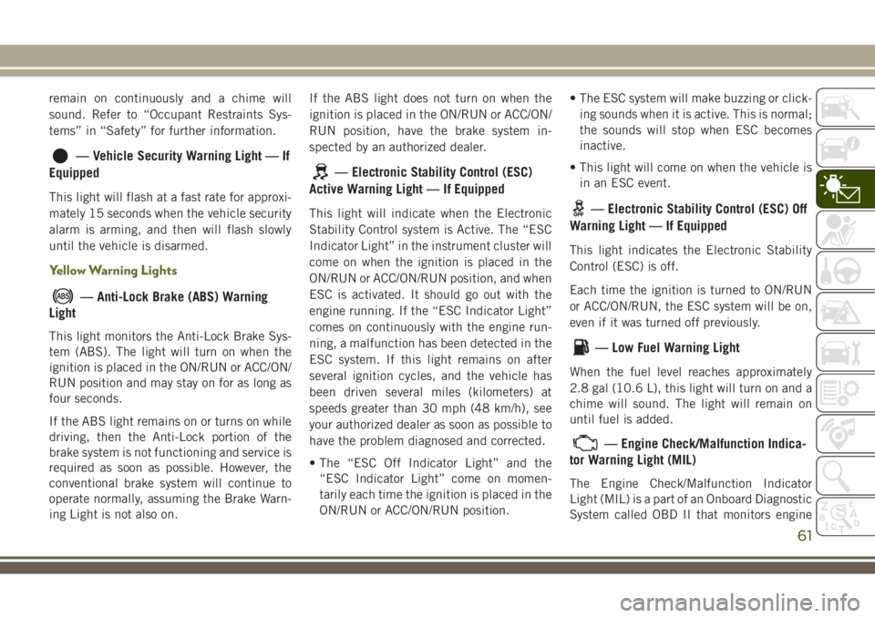
remain on continuously and a chime will
sound. Refer to “Occupant Restraints Sys-
tems” in “Safety” for further information.
— Vehicle Security Warning Light — If
Equipped
This light will flash at a fast rate for approxi-
mately 15 seconds when the vehicle security
alarm is arming, and then will flash slowly
until the vehicle is disarmed.
Yellow Warning Lights
— Anti-Lock Brake (ABS) Warning
Light
This light monitors the Anti-Lock Brake Sys-
tem (ABS). The light will turn on when the
ignition is placed in the ON/RUN or ACC/ON/
RUN position and may stay on for as long as
four seconds.
If the ABS light remains on or turns on while
driving, then the Anti-Lock portion of the
brake system is not functioning and service is
required as soon as possible. However, the
conventional brake system will continue to
operate normally, assuming the Brake Warn-
ing Light is not also on.If the ABS light does not turn on when the
ignition is placed in the ON/RUN or ACC/ON/
RUN position, have the brake system in-
spected by an authorized dealer.
— Electronic Stability Control (ESC)
Active Warning Light — If Equipped
This light will indicate when the Electronic
Stability Control system is Active. The “ESC
Indicator Light” in the instrument cluster will
come on when the ignition is placed in the
ON/RUN or ACC/ON/RUN position, and when
ESC is activated. It should go out with the
engine running. If the “ESC Indicator Light”
comes on continuously with the engine run-
ning, a malfunction has been detected in the
ESC system. If this light remains on after
several ignition cycles, and the vehicle has
been driven several miles (kilometers) at
speeds greater than 30 mph (48 km/h), see
your authorized dealer as soon as possible to
have the problem diagnosed and corrected.
• The “ESC Off Indicator Light” and the
“ESC Indicator Light” come on momen-
tarily each time the ignition is placed in the
ON/RUN or ACC/ON/RUN position.• The ESC system will make buzzing or click-
ing sounds when it is active. This is normal;
the sounds will stop when ESC becomes
inactive.
• This light will come on when the vehicle is
in an ESC event.— Electronic Stability Control (ESC) Off
Warning Light — If Equipped
This light indicates the Electronic Stability
Control (ESC) is off.
Each time the ignition is turned to ON/RUN
or ACC/ON/RUN, the ESC system will be on,
even if it was turned off previously.
— Low Fuel Warning Light
When the fuel level reaches approximately
2.8 gal (10.6 L), this light will turn on and a
chime will sound. The light will remain on
until fuel is added.
— Engine Check/Malfunction Indica-
tor Warning Light (MIL)
The Engine Check/Malfunction Indicator
Light (MIL) is a part of an Onboard Diagnostic
System called OBD II that monitors engine
61