tow JEEP WRANGLER 2020 Owner handbook (in English)
[x] Cancel search | Manufacturer: JEEP, Model Year: 2020, Model line: WRANGLER, Model: JEEP WRANGLER 2020Pages: 276, PDF Size: 4.47 MB
Page 21 of 276
DOORS
CAUTION!
Careless handling and storage of the re-
movable door panels may damage the
seals, causing water to leak into the vehi-
cle’s interior.
Upper Half Door Window Removal — If
Equipped
Grasp the half door window and pull upward.
Upper Half Door Window Installation — If
Equipped
1.Grasp the half door window and line up the
pins with the pockets in the lower door.
2. Push down to ensure the half door window
is fully seated.
Front Door Removal
WARNING!
Do not drive your vehicle on public roads
with the doors removed as you will lose the
WARNING!
protection they can provide. This proce-
dure is furnished for use during off-road
operation only.
NOTE:
Hinge pin can break if overtightened during
door reinstall (Max Torque: 10 N·m / 7.5 ft· lb).
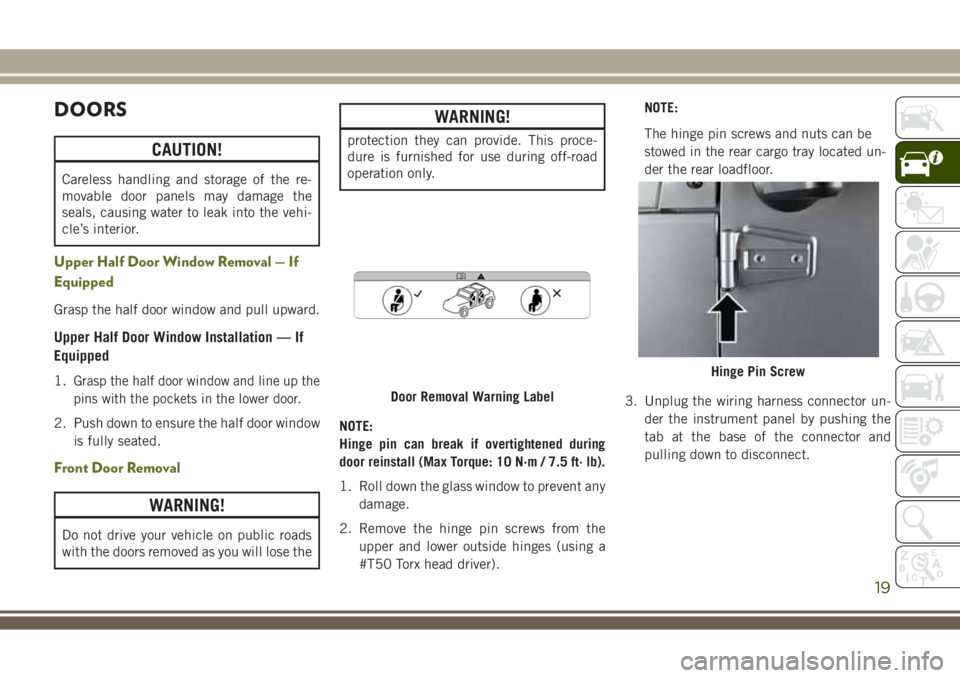
1. Roll down the glass window to prevent any
damage.
2. Remove the hinge pin screws from the
upper and lower outside hinges (using a
#T50 Torx head driver).NOTE:
The hinge pin screws and nuts can be
stowed in the rear cargo tray located un-
der the rear loadfloor.
3. Unplug the wiring harness connector un-
der the instrument panel by pushing the
tab at the base of the connector and
pulling down to disconnect.
Door Removal Warning Label
Hinge Pin Screw
19
Page 22 of 276
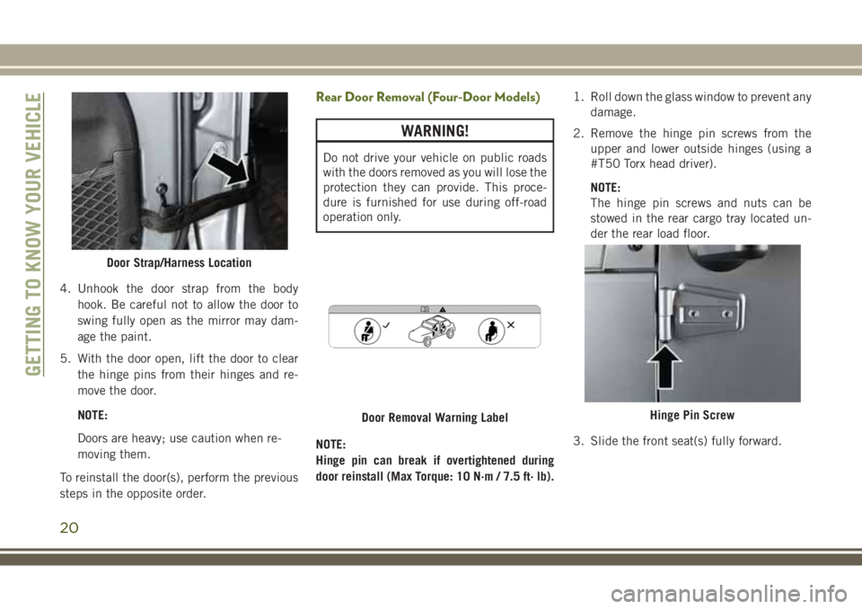
4. Unhook the door strap from the body
hook. Be careful not to allow the door to
swing fully open as the mirror may dam-
age the paint.
5. With the door open, lift the door to clear
the hinge pins from their hinges and re-
move the door.
NOTE:
Doors are heavy; use caution when re-
moving them.
To reinstall the door(s), perform the previous
steps in the opposite order.
Rear Door Removal (Four-Door Models)
WARNING!
Do not drive your vehicle on public roads
with the doors removed as you will lose the
protection they can provide. This proce-
dure is furnished for use during off-road
operation only.
NOTE:
Hinge pin can break if overtightened during
door reinstall (Max Torque: 10 N·m / 7.5 ft· lb).1. Roll down the glass window to prevent any
damage.
2. Remove the hinge pin screws from the
upper and lower outside hinges (using a
#T50 Torx head driver).
NOTE:
The hinge pin screws and nuts can be
stowed in the rear cargo tray located un-
der the rear load floor.
3. Slide the front seat(s) fully forward.
Door Strap/Harness Location
Door Removal Warning LabelHinge Pin Screw
GETTING TO KNOW YOUR VEHICLE
20
Page 25 of 276
• Be sure that the front seats are fully upright
and positioned forward. This will allow the
rear seat to fold down easily.
• Remove the center head restraint. Failure
to do so will result in the head restraint
coming in contact with the center console.
WARNING!
• It is extremely dangerous to ride in a
cargo area, inside or outside of a vehicle.
In a collision, people riding in these
areas are more likely to be seriously
injured or killed.
• Do not allow people to ride in any area of
your vehicle that is not equipped with
seats and seat belts.
• Be sure everyone in your vehicle is in a
seat and using a seat belt properly.
To Fold Down The Rear Seat
Locate the release lever (upper outboard side
of seat), and lift it upward until the seatback
releases.
Slowly fold down the seatback.NOTE:
You may experience deformation in the seat
cushion from the seat belt buckles if the
seats are left folded for an extended period of
time. This is normal. By simply opening the
seats to the open position, the seat cushion
will return to its normal shape over time.
To Raise The Rear Seat
Raise the seatback and lock it into place, and
install center head restraint. If interference
from the cargo area prevents the seatback
from fully locking, you will have difficulty
returning the seat to its proper position.
NOTE:
If the rear seatback is not fully latched, the
center shoulder belt will not be able to be
extended for use. If you cannot extend the
center shoulder belt, make sure your seat-
back is fully latched.
WARNING!
Be certain that the seatback is securely
locked into position. If the seatback is not
securely locked into position the seat will
WARNING!
not provide the proper stability for child
seats and/or passengers. An improperly
latched seat could cause serious injury.
Front Passenger Easy Entry Seat — Two
Door Models
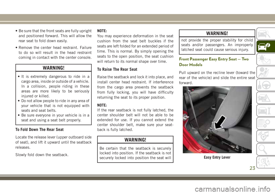
Pull upward on the recline lever (toward the
rear of the vehicle) and slide the entire seat
forward.
Easy Entry Lever
23
Page 26 of 276
To return the seat to a sitting position, rotate
the seatback upright until it locks and push
the seat rearward until the track locks.
NOTE:
• The front passenger seats have a track
memory, which returns the seat to just past
the halfway point of the track regardless of
its original position.
• The recliner and easy entry levers should
not be used during the automatic returning
of the seat to its sitting position.
Tip ‘n Slide Seats — Two Door Models
This feature allows the front seats to be
rotated toward the instrument panel to allow
easier entry into the rear seats.
Driver's Seat
Pull upward on the recline lever and bring the
seatback to its full forward position.
Rotate the entire seat assembly toward the
instrument panel.
Passenger Seat
In addition to Easy Entry, the front passenger
seat is also equipped with Tip ‘n Slide. This
feature allows for easier entry for rear passen-
gers.
Pull upward on the recline lever and slide the
entire seat forward (Easy Entry).
With the seat forward, pull the entire seat
assembly toward the instrument panel.
Removing The Rear Seat — Two Door
Models
NOTE:
• Prior to folding the rear seat, it may be
necessary to reposition the front seats.
• Be sure that the front seats are fully upright
and positioned forward. This will allow the
rear seat to fold down easily.
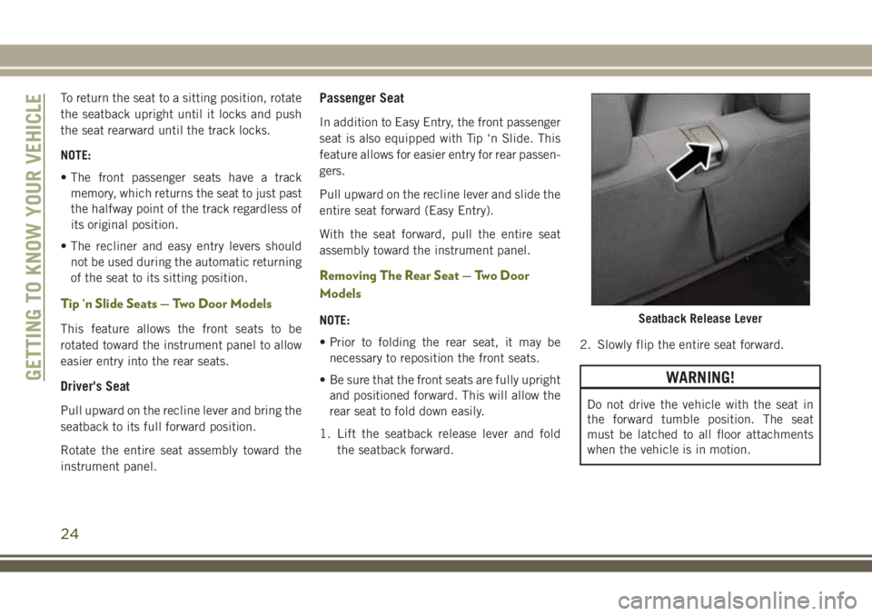
1. Lift the seatback release lever and fold
the seatback forward.2. Slowly flip the entire seat forward.
WARNING!
Do not drive the vehicle with the seat in
the forward tumble position. The seat
must be latched to all floor attachments
when the vehicle is in motion.
Seatback Release Lever
GETTING TO KNOW YOUR VEHICLE
24
Page 28 of 276
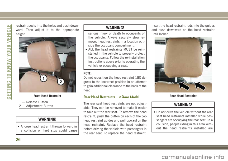
restraint posts into the holes and push down-
ward. Then adjust it to the appropriate
height.
WARNING!
• A loose head restraint thrown forward in
a collision or hard stop could cause
WARNING!
serious injury or death to occupants of
the vehicle. Always securely stow re-
moved head restraints in a location out-
side the occupant compartment.
• ALL the head restraints MUST be rein-
stalled in the vehicle to properly protect
the occupants. Follow the re-installation
instructions above prior to operating the
vehicle or occupying a seat.
NOTE:
Do not reposition the head restraint 180 de-
grees to the incorrect position in an attempt
to gain additional clearance to the back of the
head.
Rear Head Restraints — 2 Door Model
The rear seat head restraints are not adjust-
able. They can be removed to make it easier
to take out the rear seat. To remove the head
restraint, push the button on each of the two
head restraint guides and pull upward on the
head restraint. Replace the head restraint
before driving the vehicle with passengers in
the rear seat. To replace the head restraint,insert the head restraint rods into the guides
and push downward on the head restraint
until locked.WARNING!
• Do not drive the vehicle without the rear
seat head restraints installed while pas-
sengers are occupying the rear seat. In a
collision, people riding in this area with-
out the head restraints installed are
Front Head Restraint
1 — Release Button
2 — Adjustment Button
Rear Head RestraintGETTING TO KNOW YOUR VEHICLE
26
Page 29 of 276
WARNING!
more likely to be seriously injured or
killed.
• A loose head restraint thrown forward in
a collision or hard stop could cause
serious injury or death to occupants of
the vehicle. Always securely stow re-
moved head restraints in a location out-
side the occupant compartment.
• ALL the head restraints MUST be rein-
stalled in the vehicle to properly protect
the occupants. Follow the reinstallation
instructions above prior to operating the
vehicle or occupying a seat.
NOTE:
Do not reposition the head restraint 180 de-
grees to the incorrect position in an attempt
to gain additional clearance to the back of the
head.
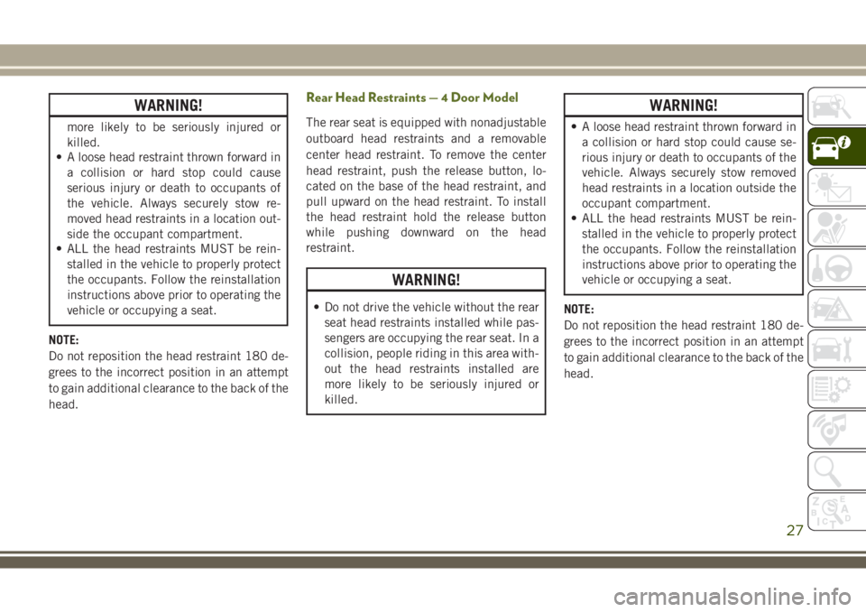
Rear Head Restraints—4DoorModel
The rear seat is equipped with nonadjustable
outboard head restraints and a removable
center head restraint. To remove the center
head restraint, push the release button, lo-
cated on the base of the head restraint, and
pull upward on the head restraint. To install
the head restraint hold the release button
while pushing downward on the head
restraint.
WARNING!
• Do not drive the vehicle without the rear
seat head restraints installed while pas-
sengers are occupying the rear seat. In a
collision, people riding in this area with-
out the head restraints installed are
more likely to be seriously injured or
killed.
WARNING!
• A loose head restraint thrown forward in
a collision or hard stop could cause se-
rious injury or death to occupants of the
vehicle. Always securely stow removed
head restraints in a location outside the
occupant compartment.
• ALL the head restraints MUST be rein-
stalled in the vehicle to properly protect
the occupants. Follow the reinstallation
instructions above prior to operating the
vehicle or occupying a seat.
NOTE:
Do not reposition the head restraint 180 de-
grees to the incorrect position in an attempt
to gain additional clearance to the back of the
head.
27
Page 31 of 276
Daytime Running Lights — If Equipped
The headlights come on at a low intensity level
when shifted into any position other than PARK
(auto transmission) or when the vehicle begins
to move (manual transmission).
NOTE:
The Daytime Running Light, on the same side
of the vehicle as the active turn signal, will
turn off automatically when a turn signal is in
operation and turn on again when the turn
signal is not operating.
High/Low Beam Switch
Push the multifunction lever toward the in-
strument panel to switch the headlights to
high beams. Pulling the multifunction lever
back toward the steering wheel will return the
lights to low beams.
Flash-To-Pass
You can signal another vehicle with your
headlights by lightly pulling the multifunc-
tion lever toward you. This will cause the high
beam headlights to turn on, and remain on,
until the lever is released.
Automatic Headlights — If Equipped
This system automatically turns the head-
lights on or off according to ambient light
levels. To turn the system on, turn the end of
the multifunction lever to the AUTO position
(third detent). When the system is on, the
Headlight Time Delay feature is also on. This
means the headlights will stay on for up to
90 seconds after you turn the ignition switch
to the LOCK position. To turn the Automatic
System off, turn the end of the multifunction
lever out of the AUTO position.
NOTE:
The engine must be running before the head-
lights will turn on in the Automatic mode.
Front Fog Lights
The front fog light switch is located on the
multifunction lever. To activate the front fog
lights, turn on the parking or low beam head-
lights and pull out the end of the lever.NOTE:
The fog lights will only operate with the park-
ing lights or the headlights on low beam.
Selecting high beam headlights will turn off
the fog lights.
Rear Fog Lights — If Equipped
The rear fog lights may be operated, as de-
sired, when visibility is poor due to fog. To
activate the rear fog lights, turn on the low
beam, high beam, or front fog lamps, pull out
the end of the multifunction lever and rotate
the lever to the last detent.
Turn Signals
Move the multifunction lever up or down and
the arrows on each side of the instrument
cluster flash to show proper operation of the
front and rear turn signal lights.
29
Page 33 of 276
lever. For information on using the rear win-
dow wiper/washer, refer to “Rear Window
Wiper/Washer” in this section for more infor-
mation.
Windshield Wiper Operation
Rotate the end of the lever upward to the
second detent past the intermittent settings
for low-speed wiper operation. Rotate the end
of the lever upward to the third detent past
the intermittent settings for high-speed wiper
operation.
CAUTION!
In cold weather, always turn off the wiper
switch and allow the wipers to return to the
park position before turning off the engine.
If the wiper switch is left on and the wipers
freeze to the windshield, damage to the
wiper motor may occur when the vehicle is
restarted.
Intermittent Wiper System
Use the intermittent wiper when weather con-
ditions make a single wiping cycle, with a
variable pause between cycles, desirable. Ro-
tate the end of the lever to the first detent
position for one of five intermittent settings.
The delay cycle can be set anywhere between
1 to 18 seconds.
NOTE:
The wiper delay times depend on vehicle
speed. If the vehicle is moving less than
10 mph (16 km/h), delay times will be
doubled.
Windshield Washers
To use the washer, pull the lever toward you
and hold while spray is desired. If the lever is
pulled while in the delay range, the wiper will
start and continue to operate for two or three
wipe cycles after the lever is released. Then,
the intermittent interval previously selected
will resume.
If the lever is pulled while in the off position,
the wipers will operate for two or three wipe
cycles. Then, the wipers will turn off.
WARNING!
Sudden loss of visibility through the wind-
shield could lead to a collision. You might
not see other vehicles or other obstacles.
To avoid sudden icing of the windshield
during freezing weather, warm the wind-
shield with the defroster before and during
windshield washer use.
Mist Feature
Push down on the wiper lever to activate a
single wipe to clear off road mist or spray
from a passing vehicle. As long as the lever is
held down, the wipers will continue to oper-
ate.
NOTE:
The mist feature does not activate the washer
pump; therefore, no washer fluid will be
sprayed on the windshield. The wash func-
tion must be used in order to spray the
windshield with washer fluid.
31
Page 62 of 276
— Battery Charge Warning Light
This light illuminates when the battery is not
charging properly. If it stays on while the
engine is running, there may be a malfunc-
tion with the charging system. Contact your
authorized dealer as soon as possible.
This indicates a possible problem with the
electrical system or a related component.
— Coolant Temperature Warning Light
This light warns of an overheated engine
condition. If the light turns on while driving,
safely pull over and stop the vehicle. If the
A/C system is on, turn it off. Also, shift the
transmission into NEUTRAL and idle the ve-
hicle. If the temperature reading does not
return to normal, turn the engine off imme-
diately and call for service.
NOTE:
As the coolant temperature gauge ap-
proaches "H," this indicator will illuminate
and a single chime will sound.
— Electronic Throttle Control (ETC)
Warning Light
This light informs you of a problem with the
Electronic Throttle Control (ETC) system. If a
problem is detected while the vehicle is run-
ning, the light will either stay on or flash
depending on the nature of the problem.
Cycle the ignition when the vehicle is safely
and completely stopped and the transmission
is placed in the PARK position. The light
should turn off. If the light remains on with
the vehicle running, your vehicle will usually
be drivable; however, see an authorized
dealer for service as soon as possible.
NOTE:
This light may turn on if the accelerator and
brake pedals are pressed at the same time.
If the light continues to flash when the ve-
hicle is running, immediate service is re-
quired and you may experience reduced per-
formance, an elevated/rough idle, or engine
stall and your vehicle may require towing.
The light will come on when the ignition is
placed in the ON/RUN or ACC/ON/RUN posi-tion and remain on briefly as a bulb check. If
the light does not come on during starting,
have the system checked by an authorized
dealer.
— Oil Pressure Warning Light
This light indicates low engine oil pressure. If
the light turns on while driving, stop the
vehicle and shut off the engine as soon as
possible. A chime will sound when this light
turns on.
Do not operate the vehicle until the cause is
corrected. This light does not indicate how
much oil is in the engine. The engine oil level
must be checked under the hood.
— Seat Belt Reminder Warning Light
This light indicates when the driver or pas-
senger seat belt is unbuckled. When the
ignition is first placed in the ON/RUN or
ACC/ON/RUN position and if the driver’s seat
belt is unbuckled, a chime will sound and the
light will turn on. When driving, if the driver
or front passenger seat belt remains unbuck-
led, the Seat Belt Reminder Light will flash or
GETTING TO KNOW YOUR INSTRUMENT PANEL
60
Page 64 of 276
and automatic transmission control systems.
The light will illuminate when the ignition is
in the ON/RUN position before engine start.
If the bulb does not come on when turning
the ignition switch from OFF to ON/RUN,
have the condition checked promptly.
Certain conditions, such as a loose or missing
gas cap, poor quality fuel, etc., may illumi-
nate the light after engine start. The vehicle
should be serviced if the light stays on
through several typical driving styles. In most
situations, the vehicle will drive normally and
will not require towing.
When the engine is running, the MIL may
flash to alert serious conditions that could
lead to immediate loss of power or severe
catalytic converter damage. The vehicle
should be serviced as soon as possible if this
occurs.
WARNING!
A malfunctioning catalytic converter, as
referenced above, can reach higher tem-
peratures than in normal operating condi-
tions. This can cause a fire if you drive
WARNING!
slowly or park over flammable substances
such as dry plants, wood, cardboard, etc.
This could result in death or serious injury
to the driver, occupants or others.
CAUTION!
Prolonged driving with the Malfunction
Indicator Light (MIL) on could cause dam-
age to the vehicle control system. It also
could affect fuel economy and driveability.
If the MIL is flashing, severe catalytic
converter damage and power loss will soon
occur. Immediate service is required.
— Tire Pressure Monitoring System
(TPMS) Warning Light
The warning light switches on and a message
is displayed to indicate that the tire pressure
is lower than the recommended value and/or
that slow pressure loss is occurring. In these
cases, optimal tire duration and fuel con-
sumption may not be guaranteed.Should one or more tires be in the condition
mentioned above, the display will show the
indications corresponding to each tire in
sequence.
CAUTION!
Do not continue driving with one or more
flat tires as handling may be compro-
mised. Stop the vehicle, avoiding sharp
braking and steering. If a tire puncture
occurs, repair immediately using the dedi-
cated tire repair kit and contact your au-
thorized dealer as soon as possible.
Each tire, including the spare (if provided),
should be checked monthly when cold and
inflated to the inflation pressure recom-
mended by the vehicle manufacturer on the
vehicle placard or tire inflation pressure la-
bel. (If your vehicle has tires of a different
size than the size indicated on the vehicle
placard or tire inflation pressure label, you
should determine the proper tire inflation
pressure for those tires.)
GETTING TO KNOW YOUR INSTRUMENT PANEL
62