steering JEEP WRANGLER 2021 Owner handbook (in English)
[x] Cancel search | Manufacturer: JEEP, Model Year: 2021, Model line: WRANGLER, Model: JEEP WRANGLER 2021Pages: 276, PDF Size: 4.47 MB
Page 134 of 276
NOTE:
Shifting into or out of 4L is possible with the
vehicle completely stopped; however, diffi-
culty may occur due to the mating teeth not
being properly aligned. Several attempts may
be required for clutch teeth alignment and
shift completion to occur. The preferred
method is with the vehicle rolling at 2 to
3 mph (3 to 5 km/h). Avoid attempting to
engage or disengage 4L with the vehicle
moving faster than 2 to 3 mph (3 to 5 km/h).
WARNING!
Failure to engage a transfer case position
completely can cause transfer case dam-
age or loss of power and vehicle control.
You could have a collision. Do not drive the
vehicle unless the transfer case is fully
engaged.
Trac-Lok Rear Axle — If Equipped
The Trac-Lok rear axle provides a constant
driving force to both rear wheels and reduces
wheel spin caused by the loss of traction at
one driving wheel. If traction differs between
the two rear wheels, the differential auto-
matically proportions the usable torque by
providing more torque to the wheel that has
traction.
Trac-Lok is especially helpful during slippery
driving conditions. With both rear wheels on a
slippery surface, a slight application of the
accelerator will supply maximum traction.
WARNING!
On vehicles equipped with a limited-slip
differential, never run the engine with one
rear wheel off the ground. The vehicle may
drive through the rear wheel remaining on
the ground and cause you to lose control of
your vehicle.
Axle Lock (Tru-Lok) — Rubicon Models
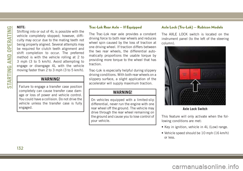
The AXLE LOCK switch is located on the
instrument panel (to the left of the steering
column).
This feature will only activate when the fol-
lowing conditions are met:
• Key in ignition, vehicle in 4L (Low) range.
• Vehicle speed should be 10 mph (16 km/h)
or less.
Axle Lock Switch
STARTING AND OPERATING
132
Page 135 of 276
To activate the system, push the bottom of
the AXLE LOCK switch once to lock the rear
axle only (the “Rear Axle Lock Indicator
Light” will illuminate), push the bottom of
the switch again to lock the front axle (the
“Front Axle Lock Indicator Light” will illumi-
nate). When the rear axle is locked, pushing
the bottom of switch again will lock or unlock
the front axle.
NOTE:
The indicator lights will flash until the axles
are fully locked or unlocked.
To unlock the axles, push the top of the AXLE
LOCK switch.
Axle lock will disengage if the vehicle is taken
out of 4L (Low) range, or the ignition switch is
turned to the OFF position.
Electronic Sway Bar Disconnect — If
Equipped
Your vehicle may be equipped with an elec-
tronic disconnecting stabilizer/sway bar. This
system allows greater front suspension travel
in off-road situations.This system is controlled by the SWAY BAR
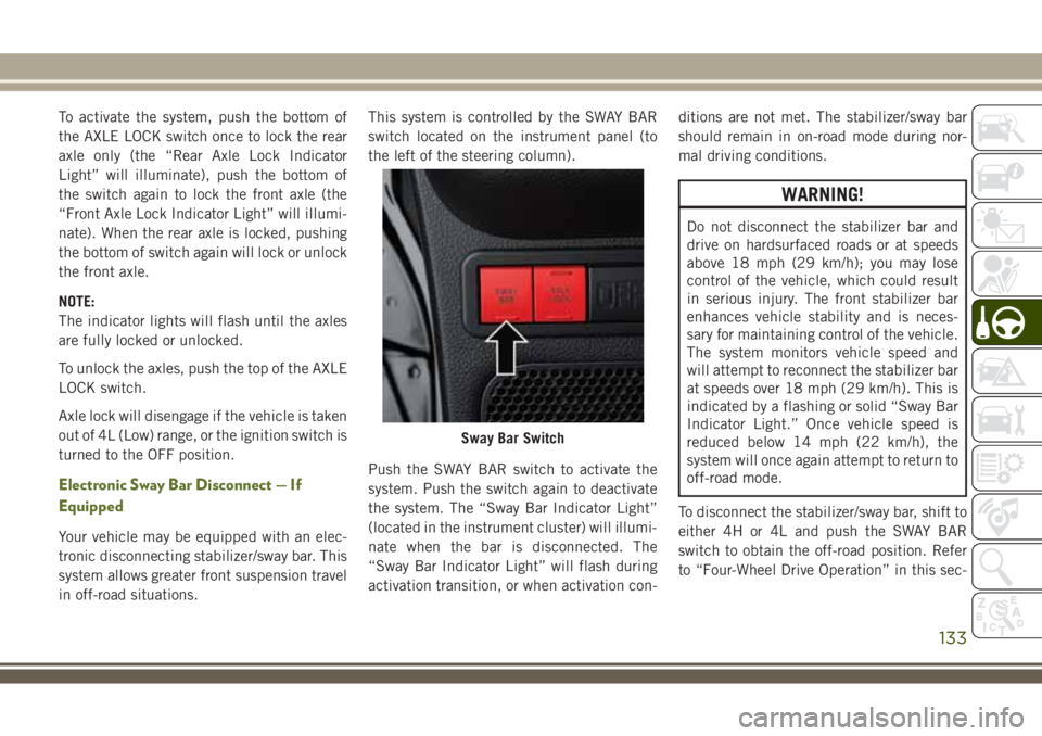
switch located on the instrument panel (to
the left of the steering column).
Push the SWAY BAR switch to activate the
system. Push the switch again to deactivate
the system. The “Sway Bar Indicator Light”
(located in the instrument cluster) will illumi-
nate when the bar is disconnected. The
“Sway Bar Indicator Light” will flash during
activation transition, or when activation con-ditions are not met. The stabilizer/sway bar
should remain in on-road mode during nor-
mal driving conditions.
WARNING!
Do not disconnect the stabilizer bar and
drive on hardsurfaced roads or at speeds
above 18 mph (29 km/h); you may lose
control of the vehicle, which could result
in serious injury. The front stabilizer bar
enhances vehicle stability and is neces-
sary for maintaining control of the vehicle.
The system monitors vehicle speed and
will attempt to reconnect the stabilizer bar
at speeds over 18 mph (29 km/h). This is
indicated by a flashing or solid “Sway Bar
Indicator Light.” Once vehicle speed is
reduced below 14 mph (22 km/h), the
system will once again attempt to return to
off-road mode.
To disconnect the stabilizer/sway bar, shift to
either 4H or 4L and push the SWAY BAR
switch to obtain the off-road position. Refer
to “Four-Wheel Drive Operation” in this sec-
Sway Bar Switch
133
Page 138 of 276
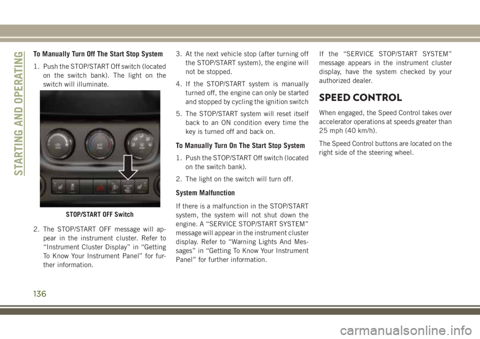
To Manually Turn Off The Start Stop System
1. Push the STOP/START Off switch (located
on the switch bank). The light on the
switch will illuminate.
2. The STOP/START OFF message will ap-
pear in the instrument cluster. Refer to
“Instrument Cluster Display” in “Getting
To Know Your Instrument Panel” for fur-
ther information.3. At the next vehicle stop (after turning off
the STOP/START system), the engine will
not be stopped.
4. If the STOP/START system is manually
turned off, the engine can only be started
and stopped by cycling the ignition switch
5. The STOP/START system will reset itself
back to an ON condition every time the
key is turned off and back on.
To Manually Turn On The Start Stop System
1. Push the STOP/START Off switch (located
on the switch bank).
2. The light on the switch will turn off.
System Malfunction
If there is a malfunction in the STOP/START
system, the system will not shut down the
engine. A “SERVICE STOP/START SYSTEM”
message will appear in the instrument cluster
display. Refer to “Warning Lights And Mes-
sages” in “Getting To Know Your Instrument
Panel” for further information.If the “SERVICE STOP/START SYSTEM”
message appears in the instrument cluster
display, have the system checked by your
authorized dealer.
SPEED CONTROL
When engaged, the Speed Control takes over
accelerator operations at speeds greater than
25 mph (40 km/h).
The Speed Control buttons are located on the
right side of the steering wheel.
STOP/START OFF Switch
STARTING AND OPERATING
136
Page 151 of 276
Rear Tail, Stop, Turn Signal, And Backup
Lamp
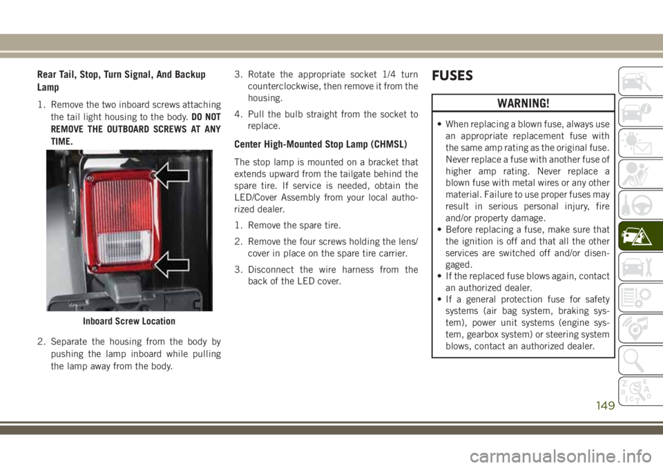
1. Remove the two inboard screws attaching
the tail light housing to the body.DO NOT
REMOVE THE OUTBOARD SCREWS AT ANY
TIME.
2. Separate the housing from the body by
pushing the lamp inboard while pulling
the lamp away from the body.3. Rotate the appropriate socket 1/4 turn
counterclockwise, then remove it from the
housing.
4. Pull the bulb straight from the socket to
replace.
Center High-Mounted Stop Lamp (CHMSL)
The stop lamp is mounted on a bracket that
extends upward from the tailgate behind the
spare tire. If service is needed, obtain the
LED/Cover Assembly from your local autho-
rized dealer.
1. Remove the spare tire.
2. Remove the four screws holding the lens/
cover in place on the spare tire carrier.
3. Disconnect the wire harness from the
back of the LED cover.
FUSES
WARNING!
• When replacing a blown fuse, always use
an appropriate replacement fuse with
the same amp rating as the original fuse.
Never replace a fuse with another fuse of
higher amp rating. Never replace a
blown fuse with metal wires or any other
material. Failure to use proper fuses may
result in serious personal injury, fire
and/or property damage.
• Before replacing a fuse, make sure that
the ignition is off and that all the other
services are switched off and/or disen-
gaged.
• If the replaced fuse blows again, contact
an authorized dealer.
• If a general protection fuse for safety
systems (air bag system, braking sys-
tem), power unit systems (engine sys-
tem, gearbox system) or steering system
blows, contact an authorized dealer.
Inboard Screw Location
149
Page 166 of 276
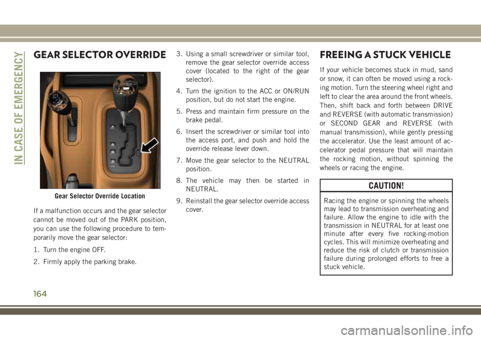
GEAR SELECTOR OVERRIDE
If a malfunction occurs and the gear selector
cannot be moved out of the PARK position,
you can use the following procedure to tem-
porarily move the gear selector:
1. Turn the engine OFF.
2. Firmly apply the parking brake.3. Using a small screwdriver or similar tool,
remove the gear selector override access
cover (located to the right of the gear
selector).
4. Turn the ignition to the ACC or ON/RUN
position, but do not start the engine.
5. Press and maintain firm pressure on the
brake pedal.
6. Insert the screwdriver or similar tool into
the access port, and push and hold the
override release lever down.
7. Move the gear selector to the NEUTRAL
position.
8. The vehicle may then be started in
NEUTRAL.
9. Reinstall the gear selector override access
cover.
FREEING A STUCK VEHICLE
If your vehicle becomes stuck in mud, sand
or snow, it can often be moved using a rock-
ing motion. Turn the steering wheel right and
left to clear the area around the front wheels.
Then, shift back and forth between DRIVE
and REVERSE (with automatic transmission)
or SECOND GEAR and REVERSE (with
manual transmission), while gently pressing
the accelerator. Use the least amount of ac-
celerator pedal pressure that will maintain
the rocking motion, without spinning the
wheels or racing the engine.
CAUTION!
Racing the engine or spinning the wheels
may lead to transmission overheating and
failure. Allow the engine to idle with the
transmission in NEUTRAL for at least one
minute after every five rocking-motion
cycles. This will minimize overheating and
reduce the risk of clutch or transmission
failure during prolonged efforts to free a
stuck vehicle.Gear Selector Override Location
IN CASE OF EMERGENCY
164
Page 172 of 276
SCHEDULED SERVICING
Scheduled Servicing — Gasoline Engine
The scheduled services listed in this manual
must be done at the times or mileages speci-
fied to protect your vehicle warranty and
ensure the best vehicle performance and re-
liability. More frequent maintenance may be
needed for vehicles in severe operating con-
ditions, such as dusty areas and very short
trip driving. Inspection and service should
also be done anytime a malfunction is sus-
pected.
The oil change indicator system will remind
you that it is time to take your vehicle in for
scheduled maintenance.
On non-instrument cluster display equipped
vehicles, “CHANgE OIL” will flash in the
instrument cluster odometer and a single
chime will sound, indicating that an oil
change is necessary.The oil change indicator message will illumi-
nate approximately 7,000 miles
(11,200 km) after the most recent oil change
was performed. Have your vehicle serviced as
soon as possible, within 500 miles (800 km).
However, an earlier oil change at 4,500 miles
(7,500 km) may be required if the vehicle is
operated under “Severe Duty Conditions”
later in this section.
NOTE:
• The oil change indicator message will not
monitor the time since the last oil change.
Change your vehicle's oil if it has been
6 months since your last oil change even if
the oil change indicator message is NOT
illuminated.
• Change your engine oil more often if you
drive your vehicle off-road for an extended
period of time.
• Under no circumstances should oil change
intervals exceed 7,500 miles (12,000 km)
or 6 months, whichever comes first.
Your authorized dealer will reset the oil
change indicator message after completing
the scheduled oil change.Once A Month Or Before A Long Trip
• Check the engine oil level about five min-
utes after a fully warmed engine is shut off.
Checking the oil level while the vehicle is
on level ground will improve the accuracy of
the oil level reading. Add oil only when the
level is at or below the ADD or MIN mark.
• Check the windshield washer solvent and
add if required.
• Check tire pressure and look for unusual
wear or damage. Rotate tires at the first
sign of irregular wear, even if it occurs
before the oil indicator system turns on.
• Inspect the battery and clean and tighten
the terminals as required.
• Check the fluid levels of coolant reservoir,
automatic transmission, brake master cyl-
inder and power steering and fill as needed.
• Check all lights and other electrical items
for correct operation.
SERVICING AND MAINTENANCE
170
Page 182 of 276
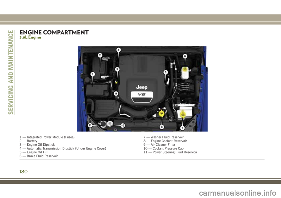
ENGINE COMPARTMENT3.6L Engine
1 — Integrated Power Module (Fuses) 7 — Washer Fluid Reservoir
2 — Battery8 — Engine Coolant Reservoir
3 — Engine Oil Dipstick 9 — Air Cleaner Filter
4 — Automatic Transmission Dipstick (Under Engine Cover) 10 — Coolant Pressure Cap
5 — Engine Oil Fill 11 — Power Steering Fluid Reservoir
6 — Brake Fluid Reservoir
SERVICING AND MAINTENANCE
180
Page 183 of 276
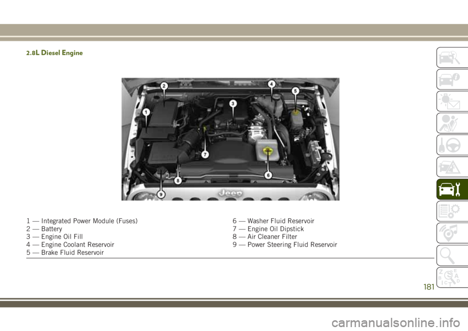
2.8L Diesel Engine
1 — Integrated Power Module (Fuses) 6 — Washer Fluid Reservoir
2 — Battery 7 — Engine Oil Dipstick
3 — Engine Oil Fill 8 — Air Cleaner Filter
4 — Engine Coolant Reservoir 9 — Power Steering Fluid Reservoir
5 — Brake Fluid Reservoir
181
Page 195 of 276

TIRES
Tires — General Information
Tire Pressure
Proper tire inflation pressure is essential to
the safe and satisfactory operation of your
vehicle. Four primary areas are affected by
improper tire pressure:
• Safety and Vehicle Stability
• Economy
• Tread Wear
• Ride Comfort
Safety
WARNING!
• Improperly inflated tires are dangerous
and can cause collisions.
• Underinflation increases tire flexing and
can result in overheating and tire failure.
• Overinflation reduces a tire's ability to
cushion shock. Objects on the road and
chuckholes can cause damage that re-
sult in tire failure.
WARNING!
• Overinflated or underinflated tires can
affect vehicle handling and can fail sud-
denly, resulting in loss of vehicle control.
• Unequal tire pressures can cause steer-
ing problems. You could lose control of
your vehicle.
• Unequal tire pressures from one side of
the vehicle to the other can cause the
vehicle to drift to the right or left.
• Always drive with each tire inflated to
the recommended cold tire inflation
pressure.
Both under-inflation and over-inflation affect
the stability of the vehicle and can produce a
feeling of sluggish response or over respon-
siveness in the steering.
NOTE:
• Unequal tire pressures from side to side
may cause erratic and unpredictable steer-
ing response.
• Unequal tire pressure from side to side may
cause the vehicle to drift left or right.Fuel EconomyUnderinflated tires will increase tire rolling re-
sistance resulting in higher fuel consumption.
Tread Wear
Improper cold tire inflation pressures can
cause abnormal wear patterns and reduced
tread life, resulting in the need for earlier tire
replacement.
Ride Comfort And Vehicle Stability
Proper tire inflation contributes to a comfort-
able ride. Over-inflation produces a jarring
and uncomfortable ride.
Tire Inflation Pressures
The proper cold tire inflation pressure is
listed on the driver's side B-Pillar or rear edge
of the driver's side door.
At least once a month:
• Check and adjust tire pressure with a good
quality pocket-type pressure gauge. Do not
make a visual judgement when determining
proper inflation. Tires may look properly
inflated even when they are under-inflated.
193
Page 198 of 276
worn to the tread wear indicators, the tire
should be replaced. Refer to “Replacement
Tires” in this section for further information.
Life Of Tire
The service life of a tire is dependent upon
varying factors including, but not limited to:
• Driving style.
•
Tire pressure - Improper cold tire inflation
pressures can cause uneven wear patterns to
develop across the tire tread. These abnormal
wear patterns will reduce tread life, resulting
in the need for earlier tire replacement.
• Distance driven.
• Performance tires, tires with a speed rating
of V or higher, and Summer tires typically
have a reduced tread life. Rotation of these
tires per the vehicle scheduled mainte-
nance is highly recommended.
WARNING!
Tires and the spare tire should be replaced
after six years, regardless of the remaining
tread. Failure to follow this warning can
result in sudden tire failure. You could lose
WARNING!
control and have a collision resulting in
serious injury or death.
Keep dismounted tires in a cool, dry place
with as little exposure to light as possible.
Protect tires from contact with oil, grease,
and gasoline.
Replacement Tires
The tires on your new vehicle provide a bal-
ance of many characteristics. They should be
inspected regularly for wear and correct cold
tire inflation pressures. The manufacturer
strongly recommends that you use tires
equivalent to the originals in size, quality and
performance when replacement is needed.
Refer to the paragraph on “Tread Wear Indi-
cators” in this section. Refer to the Tire and
Loading Information placard or the Vehicle
Certification Label for the size designation of
your tire. The Load Index and Speed Symbol
for your tire will be found on the original
equipment tire sidewall.It is recommended to replace the two front
tires or two rear tires as a pair. Replacing just
one tire can seriously affect your vehicle’s
handling. If you ever replace a wheel, make
sure that the wheel’s specifications match
those of the original wheels.
It is recommended you contact an authorized
tire dealer or original equipment dealer with
any questions you may have on tire specifi-
cations or capability. Failure to use equiva-
lent replacement tires may adversely affect
the safety, handling, and ride of your vehicle.
WARNING!
• Do not use a tire, wheel size, load rating,
or speed rating other than that specified
for your vehicle. Some combinations of
unapproved tires and wheels may
change suspension dimensions and per-
formance characteristics, resulting in
changes to steering, handling, and brak-
ing of your vehicle. This can cause un-
predictable handling and stress to steer-
ing and suspension components. You
could lose control and have a collisionSERVICING AND MAINTENANCE
196