light JEEP WRANGLER 2021 Owner handbook (in English)
[x] Cancel search | Manufacturer: JEEP, Model Year: 2021, Model line: WRANGLER, Model: JEEP WRANGLER 2021Pages: 276, PDF Size: 4.47 MB
Page 121 of 276
After Starting
The idle speed is controlled automatically,
and it will decrease as the engine warms up.
Normal Starting — Diesel Engine
1. The gear selector must be in the NEU-
TRAL or PARK position before you can
start the engine.
2. Turn the ignition key to the ON position.
3. Watch for the “Wait To Start Light” in the
instrument cluster. Refer to “Instrument
Cluster” in “Getting To Know Your Instru-
ment Panel” for further review. It will glow
for two to ten seconds or more, depending
on engine temperature. When the “Wait
To Start Light” goes out, the engine is
ready to start.
4. Tip Start Feature (Automatic Transmission
Only)
Do notpress the accelerator. Turn the
ignition key to the START position and
then release it. The starter motor will
continue to run, and it will automatically
disengage when the engine is running. If
the engine fails to start, the starter willdisengage automatically in 25 seconds.
If this occurs, turn the ignition switch to
the LOCK position, wait 25 to 30 sec-
onds, then repeat the “Normal Starting”
procedure.
NOTE:
The starter motor may run up to 30 sec-
onds in very cold conditions until the
engine is started. The starter can be dis-
engaged by turning the ignition key to
the OFF position, if required.
5. Without Tip Start Feature (Manual Trans-
mission Only)
Turn the ignition switch to the START
position and release when the engine
starts. If the engine fails to start within
10 seconds, turn the ignition switch to
the LOCK position, wait 10 to 15 sec-
onds, then repeat the “Normal Starting”
procedure.
6. After the engine starts, allow it to idle for
approximately 30 seconds before driving.
This allows oil to circulate and lubricate
the turbocharger.
Diesel Engine Warm-Up
Avoid full throttle operation when the engine
is cold. When starting a cold engine, bring the
engine up to operating speed slowly to allow
the oil pressure to stabilize as the engine
warms up.
NOTE:
High-speed, no-load running of a cold engine
can result in excessive white smoke and poor
engine performance. No-load engine speeds
should be kept under 1,200 rpm during the
warm-up period, especially in cold, ambient
temperature conditions.
If temperatures are below 32°F (0°C), oper-
ate the engine at moderate speeds for five
minutes before full loads are applied.
Diesel Engine Idling — In Cold Weather
Avoid prolonged idling in ambient tempera-
tures below 0°F (-18°C). Long periods of
idling may be harmful to your engine because
combustion chamber temperatures can drop
so low that the fuel may not burn completely.
Incomplete combustion allows carbon and
varnish to form on piston rings and injector
119
Page 123 of 276
ENGINE BREAK-IN
RECOMMENDATIONS
A long break-in period is not required for the
engine and drivetrain (transmission and axle)
in your vehicle.
Drive moderately during the first 300 miles
(500 km). After the initial 60 miles
(100 km), speeds up to 50 or 55 mph (80 or
90 km/h) are desirable.
While cruising, brief full-throttle acceleration
within the limits of local traffic laws contrib-
utes to a good break-in. Wide-open throttle
acceleration in low gear can be detrimental
and should be avoided.
The engine oil installed in the engine at the
factory is a high-quality energy conserving
type lubricant. Oil changes should be consis-
tent with anticipated climate conditions un-
der which vehicle operations will occur. For
the recommended viscosity and quality
grades, refer to “Dealer Service” in “Servic-
ing And Maintenance”.
CAUTION!
Never use Non-Detergent Oil or Straight
Mineral Oil in the engine or damage may
result.
NOTE:
A new engine may consume some oil during
its first few thousand miles (kilometers) of
operation. This should be considered a nor-
mal part of the break-in and not interpreted
as a problem.
PARKING BRAKE
Before exiting the vehicle, make sure that the
parking brake is fully applied. Also, be cer-
tain to leave an automatic transmission in
PARK, or manual transmission in REVERSE
or FIRST gear.
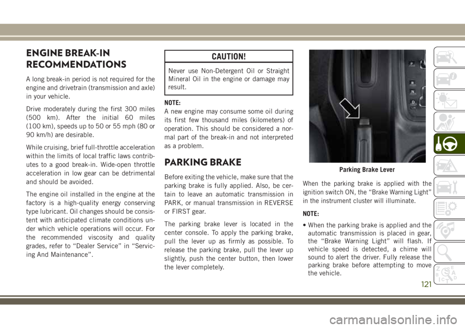
The parking brake lever is located in the
center console. To apply the parking brake,
pull the lever up as firmly as possible. To
release the parking brake, pull the lever up
slightly, push the center button, then lower
the lever completely.When the parking brake is applied with the
ignition switch ON, the “Brake Warning Light”
in the instrument cluster will illuminate.
NOTE:
• When the parking brake is applied and the
automatic transmission is placed in gear,
the “Brake Warning Light” will flash. If
vehicle speed is detected, a chime will
sound to alert the driver. Fully release the
parking brake before attempting to move
the vehicle.
Parking Brake Lever
121
Page 124 of 276
• This light only shows that the parking brake
is applied. It does not show the degree of
brake application.
When parking on a hill, it is important to turn
the front wheels toward the curb on a down-
hill grade and away from the curb on an uphill
grade. For vehicles equipped with an auto-
matic transmission, apply the parking brake
before placing the gear selector in PARK,
otherwise the load on the transmission lock-
ing mechanism may make it difficult to move
the gear selector out of PARK. The parking
brake should always be applied whenever the
driver is not in the vehicle.
WARNING!
• Never use the PARK position on an au-
tomatic transmission as a substitute for
the parking brake. Always apply the
parking brake fully when parked to guard
WARNING!
against vehicle movement and possible
injury or damage.
• When exiting the vehicle, always remove
the key fob from the ignition and lock
your vehicle.
• Never leave children alone in a vehicle,
or with access to an unlocked vehicle.
Allowing children to be in a vehicle un-
attended is dangerous for a number of
reasons. A child or others could be seri-
ously or fatally injured. Children should
be warned not to touch the parking
brake, brake pedal or the gear selector.
• Do not leave the key fob in or near the
vehicle, or in a location accessible to
children. A child could operate power
windows, other controls, or move the
vehicle.
• Be sure the parking brake is fully disen-
gaged before driving; failure to do so can
lead to brake failure and a collision.
WARNING!
• Always fully apply the parking brake
when leaving your vehicle or it may roll
and cause damage or injury. Also, be
certain to leave an automatic transmis-
sion in PARK, a manual transmission in
REVERSE or first gear. Failure to do so
may cause the vehicle to roll and cause
damage or injury.
CAUTION!
If the “Brake Warning Light” remains on
with the parking brake released, a brake
system malfunction is indicated. Have the
brake system serviced by an authorized
dealer immediately.
STARTING AND OPERATING
122
Page 125 of 276
MANUAL TRANSMISSION —
IF EQUIPPED
WARNING!
You or others could be injured if you leave
the vehicle unattended without having the
parking brake fully applied. The parking
brake should always be applied when the
driver is not in the vehicle, especially on an
incline.
CAUTION!
Never drive with your foot resting on the
clutch pedal, or attempt to hold the ve-
hicle on a hill with the clutch pedal par-
CAUTION!
tially engaged, as this will cause abnormal
wear on the clutch.
NOTE:
During cold weather, you may experience
increased effort in shifting until the transmis-
sion fluid warms up. This is normal.
Shifting
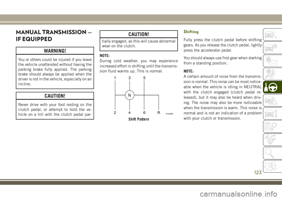
Fully press the clutch pedal before shifting
gears. As you release the clutch pedal, lightly
press the accelerator pedal.
You should always use first gear when starting
from a standing position.
NOTE:
A certain amount of noise from the transmis-
sion is normal. This noise can be most notice-
able when the vehicle is idling in NEUTRAL
with the clutch engaged (clutch pedal re-
leased), but it may also be heard when driv-
ing. The noise may also be more noticeable
when the transmission is warm. This noise is
normal and is not an indication of a problem
with your clutch or transmission.
Shift Pattern
123
Page 132 of 276
positions on hard-surfaced roads will cause
increased tire wear and damage to the drive-
line components. Refer to “Shifting Proce-
dures” in this section for further information
on shifting into 4H or 4L.
The “4WD Indicator Light” (located in the
instrument cluster) alerts the driver that the
vehicle is in four-wheel drive, and the front
and rear driveshafts are locked together. The
light will illuminate when the transfer case is
shifted into the 4H position.
NOTE:
Do not attempt to shift when only the front or
rear wheels are spinning. The transfer case is
not equipped with a synchronizer, and the
front and rear driveshaft speeds must be
equal for a shift to take place. Shifting while
the front or rear wheels are spinning at differ-
ent speeds can cause damage to the transfer
case.When operating your vehicle in 4L, the en-
gine speed will be approximately three times
(four times for Rubicon models) that of the
2H or 4H positions at a given road speed.
Take care not to overspeed the engine.
Proper operation of four-wheel drive vehicles
depends on tires of equal size, type, and
circumference on each wheel. Any difference
will adversely affect shifting and cause dam-
age to the transfer case.
Because four-wheel drive provides improved
traction, there is a tendency to exceed safe
turning and stopping speeds. Do not go faster
than road conditions permit.Shift Positions
For additional information on the appropriate
use of each 4WD system mode position, see
the information below:
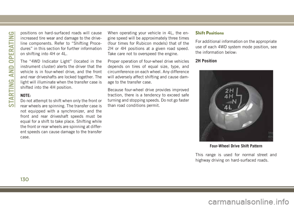
2H Position
This range is used for normal street and
highway driving on hard-surfaced roads.
Four-Wheel Drive Shift Pattern
STARTING AND OPERATING
130
Page 133 of 276
4H Position
This range locks the front and rear driveshafts
together, forcing the front and rear wheels to
rotate at the same speed. This range (4H)
provides additional traction for loose, slip-
pery road surfaces and should not be used on
dry pavement.
The “4WD Indicator Light” (located in the
instrument cluster) will illuminate when the
transfer case is shifted into the 4H position.
N (Neutral) Position
This range disengages the front and rear
driveshafts from the powertrain. It is to be
used for flat towing behind another vehicle.
Refer to “Recreational Towing” in “Starting
And Operating” for further information.
WARNING!
You or others could be injured or killed if
you leave the vehicle unattended with the
transfer case in the NEUTRAL (N) position
without first fully engaging the parking
brake. The transfer case NEUTRAL (N)
position disengages both the front and rear
WARNING!
driveshafts from the powertrain, and will
allow the vehicle to roll, even if the auto-
matic transmission is in PARK (or manual
transmission is in gear). The parking brake
should always be applied when the driver
is not in the vehicle.
4L Position
This range locks the front and rear driveshafts
together, forcing the front and rear wheels to
rotate at the same speed. This range (4L)
provides additional traction and maximum
pulling power for loose, slippery road sur-
faces only. Do not exceed 25 mph (40 km/h).
CAUTION!
Exceeding 25 mph (40 km/h) while the
transfer case is engaged in 4L may result
in an engine overspeed condition and en-
gine damage.
The “4WD Indicator Light” (located in the
instrument cluster) will illuminate when the
transfer case is shifted into the 4L position.NOTE:
When in 4L, the “ESC Off Indicator Light”
will display in the instrument cluster.
Shifting Procedures
2H to 4H or 4H to 2H
Shifting between 2H and 4H can be made
with the vehicle stopped or in motion. With
the vehicle in motion, the transfer case will
engage/disengage faster if you momentarily
release the accelerator pedal after complet-
ing the shift. Apply a constant force when
shifting the transfer case lever.
4H to 4L or 4L to 4H
With the vehicle rolling at 2 to 3 mph (3 to
5 km/h), shift an automatic transmission into
NEUTRAL (N), or press the clutch pedal on a
manual transmission. While the vehicle is
coasting at 2 to 3 mph (3 to 5 km/h), shift the
transfer case lever firmly to the desired posi-
tion. Do not pause with the transfer case in N
(Neutral). Once the shift is completed, place
the automatic transmission into DRIVE or
release the clutch pedal on a manual trans-
mission.
131
Page 134 of 276
NOTE:
Shifting into or out of 4L is possible with the
vehicle completely stopped; however, diffi-
culty may occur due to the mating teeth not
being properly aligned. Several attempts may
be required for clutch teeth alignment and
shift completion to occur. The preferred
method is with the vehicle rolling at 2 to
3 mph (3 to 5 km/h). Avoid attempting to
engage or disengage 4L with the vehicle
moving faster than 2 to 3 mph (3 to 5 km/h).
WARNING!
Failure to engage a transfer case position
completely can cause transfer case dam-
age or loss of power and vehicle control.
You could have a collision. Do not drive the
vehicle unless the transfer case is fully
engaged.
Trac-Lok Rear Axle — If Equipped
The Trac-Lok rear axle provides a constant
driving force to both rear wheels and reduces
wheel spin caused by the loss of traction at
one driving wheel. If traction differs between
the two rear wheels, the differential auto-
matically proportions the usable torque by
providing more torque to the wheel that has
traction.
Trac-Lok is especially helpful during slippery
driving conditions. With both rear wheels on a
slippery surface, a slight application of the
accelerator will supply maximum traction.
WARNING!
On vehicles equipped with a limited-slip
differential, never run the engine with one
rear wheel off the ground. The vehicle may
drive through the rear wheel remaining on
the ground and cause you to lose control of
your vehicle.
Axle Lock (Tru-Lok) — Rubicon Models
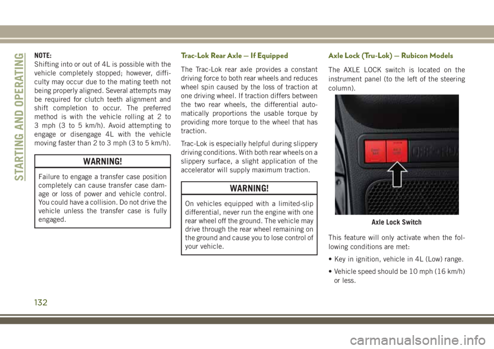
The AXLE LOCK switch is located on the
instrument panel (to the left of the steering
column).
This feature will only activate when the fol-
lowing conditions are met:
• Key in ignition, vehicle in 4L (Low) range.
• Vehicle speed should be 10 mph (16 km/h)
or less.
Axle Lock Switch
STARTING AND OPERATING
132
Page 135 of 276
To activate the system, push the bottom of
the AXLE LOCK switch once to lock the rear
axle only (the “Rear Axle Lock Indicator
Light” will illuminate), push the bottom of
the switch again to lock the front axle (the
“Front Axle Lock Indicator Light” will illumi-
nate). When the rear axle is locked, pushing
the bottom of switch again will lock or unlock
the front axle.
NOTE:
The indicator lights will flash until the axles
are fully locked or unlocked.
To unlock the axles, push the top of the AXLE
LOCK switch.
Axle lock will disengage if the vehicle is taken
out of 4L (Low) range, or the ignition switch is
turned to the OFF position.
Electronic Sway Bar Disconnect — If
Equipped
Your vehicle may be equipped with an elec-
tronic disconnecting stabilizer/sway bar. This
system allows greater front suspension travel
in off-road situations.This system is controlled by the SWAY BAR
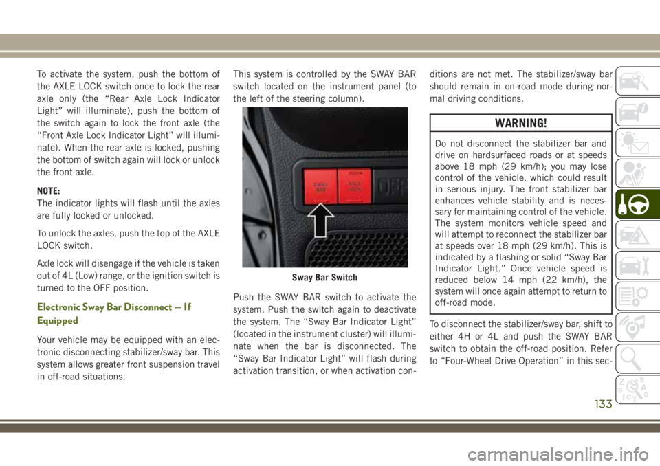
switch located on the instrument panel (to
the left of the steering column).
Push the SWAY BAR switch to activate the
system. Push the switch again to deactivate
the system. The “Sway Bar Indicator Light”
(located in the instrument cluster) will illumi-
nate when the bar is disconnected. The
“Sway Bar Indicator Light” will flash during
activation transition, or when activation con-ditions are not met. The stabilizer/sway bar
should remain in on-road mode during nor-
mal driving conditions.
WARNING!
Do not disconnect the stabilizer bar and
drive on hardsurfaced roads or at speeds
above 18 mph (29 km/h); you may lose
control of the vehicle, which could result
in serious injury. The front stabilizer bar
enhances vehicle stability and is neces-
sary for maintaining control of the vehicle.
The system monitors vehicle speed and
will attempt to reconnect the stabilizer bar
at speeds over 18 mph (29 km/h). This is
indicated by a flashing or solid “Sway Bar
Indicator Light.” Once vehicle speed is
reduced below 14 mph (22 km/h), the
system will once again attempt to return to
off-road mode.
To disconnect the stabilizer/sway bar, shift to
either 4H or 4L and push the SWAY BAR
switch to obtain the off-road position. Refer
to “Four-Wheel Drive Operation” in this sec-
Sway Bar Switch
133
Page 136 of 276
tion for further information. The “Sway Bar
Indicator Light” will flash until the stabilizer/
sway bar has been fully disconnected.
NOTE:
The stabilizer/sway bar may be torque locked
due to left and right suspension height differ-
ences. This condition is due to driving sur-
face differences or vehicle loading. In order
for the stabilizer/sway bar to disconnect/
reconnect, the right and left halves of the bar
must be aligned. This alignment may require
that the vehicle be driven onto level ground or
rocked from side to side.
To return to on-road mode, push the SWAY
BAR switch again.
WARNING!
If the stabilizer/sway bar will not return to
on-road mode, the “Sway Bar Indicator
Light” will flash in the instrument cluster
and vehicle stability is greatly reduced. Do
not attempt to drive the vehicle over
18 mph (29 km/h). Driving faster than
18 mph (29 km/ h) may cause loss of
control of the vehicle, which could result
WARNING!
in serious injury. Contact your local autho-
rized dealer for assistance.
STOP/START SYSTEM —
DIESEL MODELS WITH
MANUAL TRANSMISSION
ONLY
The Stop/Start function is developed to save
fuel and reduce emissions. The system will
stop the engine automatically during a ve-
hicle stop if the required conditions are met.
Pressing the clutch pedal will automatically
restart the vehicle.
Automatic Mode
The Stop/Start feature is en-
abled after every normal cus-
tomer engine start. It will remain
in STOP/START NOT READY un-
til you drive forward with a ve-
hicle speed greater than 3 mph (5 km/h). Atthat time, the system will go into STOP/
START READY and if all other conditions are
met, can go into an STOP/START AUTO STOP
ACTIVE mode.
To Activate The STOP/START AUTO STOP ACTIVE
Mode, The Following Must Occur:
• The system must be in STOP/START
READY state. A STOP/START READY mes-
sage will be displayed in the instrument
cluster. Refer to “Instrument Cluster Dis-
play” in “Getting To Know Your Instrument
Panel” for further information.
• Vehicle speed must be less 3 mph (5 km/h).
• The gear selector must be in the NEUTRAL
position and the clutch pedal must be fully
released
The engine will shut down,the tachometer will
fall to the Stop/Start position,the STOP/START
AUTO STOP ACTIVE message will appear,
and the heater/air conditioning (HVAC) air
flow will be reduced.
STARTING AND OPERATING
134
Page 138 of 276
To Manually Turn Off The Start Stop System
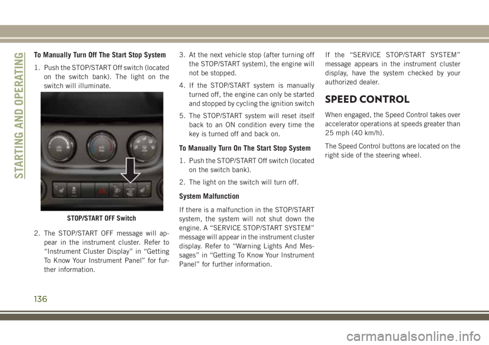
1. Push the STOP/START Off switch (located
on the switch bank). The light on the
switch will illuminate.
2. The STOP/START OFF message will ap-
pear in the instrument cluster. Refer to
“Instrument Cluster Display” in “Getting
To Know Your Instrument Panel” for fur-
ther information.3. At the next vehicle stop (after turning off
the STOP/START system), the engine will
not be stopped.
4. If the STOP/START system is manually
turned off, the engine can only be started
and stopped by cycling the ignition switch
5. The STOP/START system will reset itself
back to an ON condition every time the
key is turned off and back on.
To Manually Turn On The Start Stop System
1. Push the STOP/START Off switch (located
on the switch bank).
2. The light on the switch will turn off.
System Malfunction
If there is a malfunction in the STOP/START
system, the system will not shut down the
engine. A “SERVICE STOP/START SYSTEM”
message will appear in the instrument cluster
display. Refer to “Warning Lights And Mes-
sages” in “Getting To Know Your Instrument
Panel” for further information.If the “SERVICE STOP/START SYSTEM”
message appears in the instrument cluster
display, have the system checked by your
authorized dealer.
SPEED CONTROL
When engaged, the Speed Control takes over
accelerator operations at speeds greater than
25 mph (40 km/h).
The Speed Control buttons are located on the
right side of the steering wheel.
STOP/START OFF Switch
STARTING AND OPERATING
136