ECO mode JEEP WRANGLER 2021 Owner handbook (in English)
[x] Cancel search | Manufacturer: JEEP, Model Year: 2021, Model line: WRANGLER, Model: JEEP WRANGLER 2021Pages: 276, PDF Size: 4.47 MB
Page 17 of 276
• Ignition key removed from ignition
• Battery at an acceptable charge level
• System not disabled from previous remote
start event
• Vehicle security alarm not active
WARNING!
• Do not start or run an engine in a closed
garage or confined area. Exhaust gas
contains Carbon Monoxide (CO) which is
odorless and colorless. Carbon Monox-
ide is poisonous and can cause serious
injury or death when inhaled.
• Keep key fobs away from children. Op-
eration of the Remote Start System, win-
dows, door locks or other controls could
cause serious injury or death.
Remote Start Abort Message
The following messages will display in the
instrument cluster display if the vehicle fails to
remote start or exits remote start prematurely:
• Remote Start Aborted — Door Open
• Remote Start Aborted — Hood Open
• Remote Start Aborted — Fuel Low
• Remote Start Aborted — Swing Gate Open
• Remote Start Aborted — System Fault
The instrument cluster display message stays
active until the ignition is turned to the ON/
RUN position.
To Enter Remote Start
Push and release the remote start button on
the key fob twice within five seconds. The
vehicle doors will lock, the parking lights will
flash and the horn will chirp twice (if pro-
grammed). Then, the engine will start and the
vehicle will remain in the remote start mode
for a 15-minute cycle.NOTE:
• The park lamps will turn on and remain on
during remote start mode.
• For security, power window operation is
disabled when the vehicle is in the remote
start mode.
• The engine can be started two consecutive
times (two 15-minute cycles) with the key
fob. However, the ignition switch must be
cycled to the ON/RUN position before you
can repeat the start sequence for a third
cycle.
Remote start will also cancel if any of the
following occur:
• The engine stalls or RPM exceeds 2500.
• Any engine warning lamps come on.
• The hood is opened.
• The hazard switch is pushed.
• The transmission is moved out of PARK.
• The brake pedal is pushed.
15
Page 18 of 276
To Exit Remote Start Mode Without
Driving The Vehicle
Push and release the remote start button one
time or allow the engine to run for the entire
15-minute cycle.
NOTE:
To avoid unintentional shut downs, the sys-
tem will disable the one time push of the
remote start button for two seconds after
receiving a valid remote start request.
To Exit Remote Start Mode And Drive The
Vehicle
Before the end of the 15-minute cycle, push
and release the unlock button on the key fob
to unlock the doors and disarm the vehicle
security alarm (if equipped). Then, insert the
key into the ignition and place the ignition in
the ON/RUN position.
NOTE:
The ignition must be placed in the ON/RUN
position in order to drive the vehicle.
SENTRY KEY
The Sentry Key Immobilizer System prevents
unauthorized vehicle operation by disabling
the engine. The system does not need to be
armed or activated. Operation is automatic,
regardless of whether the vehicle is locked or
unlocked.
The system uses key fobs that have an em-
bedded electronic chip (transponder) to pre-
vent unauthorized vehicle operation. There-
fore, only key fobs that are programmed to
the vehicle can be used to start and operate
the vehicle. The system will shut the engine
off in two seconds if someone uses an invalid
key to try to start the engine.
NOTE:
A key fob that has not been programmed is
also considered an invalid key, even if it is cut
to fit the ignition or lock cylinder for that
vehicle.
During normal operation, after placing the
ignition in the on position, the vehicle secu-
rity light will turn on for three seconds for abulb check. If the light remains on after the
bulb check, it indicates that there is a prob-
lem with the electronics. In addition, if the
vehicle security light begins to flash after the
bulb check, it indicates that someone used
an invalid key to try to start the engine. Either
of these conditions will result in the engine
being shut off after two seconds.
If the vehicle security light turns on during
normal vehicle operation (vehicle running for
longer than ten seconds), it indicates that
there is a fault in the electronics. Should this
occur, have the vehicle serviced as soon as
possible by an authorized dealer.
CAUTION!
The Sentry Key Immobilizer system is not
compatible with some aftermarket remote
starting systems. Use of these systems
may result in vehicle starting problems
and loss of security protection.
All of the key fobs provided with your new
vehicle have been programmed to the vehicle
electronics.GETTING TO KNOW YOUR VEHICLE
16
Page 24 of 276
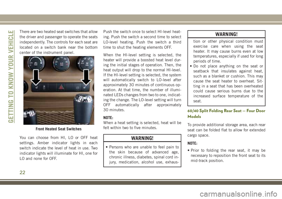
There are two heated seat switches that allow
the driver and passenger to operate the seats
independently. The controls for each seat are
located on a switch bank near the bottom
center of the instrument panel.
You can choose from HI, LO or OFF heat
settings. Amber indicator lights in each
switch indicate the level of heat in use. Two
indicator lights will illuminate for HI, one for
LO and none for OFF.Push the switch once to select HI-level heat-
ing. Push the switch a second time to select
LO-level heating. Push the switch a third
time to shut the heating elements OFF.
When the HI-level setting is selected, the
heater will provide a boosted heat level dur-
ing the initial stages of operation. Then, the
heat output will drop to the normal HI-level.
If the HI-level setting is selected, the system
will automatically switch to LO-level after
approximately 30 minutes of continuous op-
eration. At that time, the number of illumi-
nated LEDs changes from two to one, indicat-
ing the change. The LO-level setting will turn
OFF automatically after approximately
30 minutes.
NOTE:
When a heat setting is selected, heat will be
felt within two to five minutes.
WARNING!
• Persons who are unable to feel pain to
the skin because of advanced age,
chronic illness, diabetes, spinal cord in-
jury, medication, alcohol use, exhaus-
WARNING!
tion or other physical condition must
exercise care when using the seat
heater. It may cause burns even at low
temperatures, especially if used for long
periods of time.
• Do not place anything on the seat or
seatback that insulates against heat,
such as a blanket or cushion. This may
cause the seat heater to overheat. Sit-
ting in a seat that has been overheated
could cause serious burns due to the
increased surface temperature of the
seat.
60/40 Split Folding Rear Seat — Four Door
Models
To provide additional storage area, each rear
seat can be folded flat to allow for extended
cargo space.
NOTE:
• Prior to folding the rear seat, it may be
necessary to reposition the front seat to its
mid-track position.Front Heated Seat Switches
GETTING TO KNOW YOUR VEHICLE
22
Page 31 of 276
Daytime Running Lights — If Equipped
The headlights come on at a low intensity level
when shifted into any position other than PARK
(auto transmission) or when the vehicle begins
to move (manual transmission).
NOTE:
The Daytime Running Light, on the same side
of the vehicle as the active turn signal, will
turn off automatically when a turn signal is in
operation and turn on again when the turn
signal is not operating.
High/Low Beam Switch
Push the multifunction lever toward the in-
strument panel to switch the headlights to
high beams. Pulling the multifunction lever
back toward the steering wheel will return the
lights to low beams.
Flash-To-Pass
You can signal another vehicle with your
headlights by lightly pulling the multifunc-
tion lever toward you. This will cause the high
beam headlights to turn on, and remain on,
until the lever is released.
Automatic Headlights — If Equipped
This system automatically turns the head-
lights on or off according to ambient light
levels. To turn the system on, turn the end of
the multifunction lever to the AUTO position
(third detent). When the system is on, the
Headlight Time Delay feature is also on. This
means the headlights will stay on for up to
90 seconds after you turn the ignition switch
to the LOCK position. To turn the Automatic
System off, turn the end of the multifunction
lever out of the AUTO position.
NOTE:
The engine must be running before the head-
lights will turn on in the Automatic mode.
Front Fog Lights
The front fog light switch is located on the
multifunction lever. To activate the front fog
lights, turn on the parking or low beam head-
lights and pull out the end of the lever.NOTE:
The fog lights will only operate with the park-
ing lights or the headlights on low beam.
Selecting high beam headlights will turn off
the fog lights.
Rear Fog Lights — If Equipped
The rear fog lights may be operated, as de-
sired, when visibility is poor due to fog. To
activate the rear fog lights, turn on the low
beam, high beam, or front fog lamps, pull out
the end of the multifunction lever and rotate
the lever to the last detent.
Turn Signals
Move the multifunction lever up or down and
the arrows on each side of the instrument
cluster flash to show proper operation of the
front and rear turn signal lights.
29
Page 36 of 276
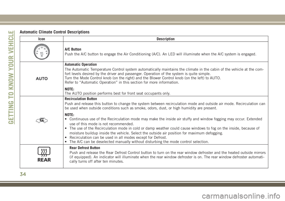
Automatic Climate Control Descriptions
Icon Description
A/C Button
Push the A/C button to engage the Air Conditioning (A/C). An LED will illuminate when the A/C system is engaged.
Automatic Operation
The Automatic Temperature Control system automatically maintains the climate in the cabin of the vehicle at the com-
fort levels desired by the driver and passenger. Operation of the system is quite simple.
Turn the Mode Control knob (on the right) and the Blower Control knob (on the left) to AUTO.
Refer to “Automatic Operation” in this section for more information.
NOTE:
The AUTO position performs best for front seat occupants only.
Recirculation Button
Push and release this button to change the system between recirculation mode and outside air mode. Recirculation can
be used when outside conditions such as smoke, odors, dust, or high humidity are present.
NOTE:
• Continuous use of the Recirculation mode may make the inside air stuffy and window fogging may occur. Extended
use of this mode is not recommended.
• The use of the Recirculation mode in cold or damp weather could cause windows to fog on the inside, because of
moisture buildup inside the vehicle. Select the outside air position for maximum defogging.
• Recirculation can be used in all modes except for Defrost.
• The A/C can be deselected manually without disturbing the mode control selection.
Rear Defrost Button
Push and release the Rear Defrost Control button to turn on the rear window defroster and the heated outside mirrors
(if equipped). An indicator will illuminate when the rear window defroster is on. The rear window defroster automati-
cally turns off after ten minutes.
GETTING TO KNOW YOUR VEHICLE
34
Page 39 of 276
Automatic Temperature Control (ATC) —
If Equipped
Automatic Operation
1. Push the AUTO button on the faceplate on
the Automatic Temperature Control (ATC)
Panel.
2. Next, adjust the temperature you would
like the system to maintain by adjusting
the driver and passenger temperature
control buttons. Once the desired tem-
perature is displayed, the system will
achieve and automatically maintain that
comfort level.
3. When the system is set up for your comfort
level, it is not necessary to change the
settings. You will experience the greatest
efficiency by simply allowing the system
to function automatically.
NOTE:
• It is not necessary to move the temperature
settings for cold or hot vehicles. The system
automatically adjusts the temperature,
mode, and blower speed to provide comfort
as quickly as possible.To provide you with maximum comfort in the
Automatic mode during cold start-ups, the
blower fan will remain on low until the engine
warms up. The blower will increase in speed
and transition into Auto mode.
Manual Operation Override
This system offers a full complement of
manual override features. The AUTO symbol
in the front ATC display will be turned off
when the system is being used in the manual
mode.
Operating Tips
Summer Operation
The engine cooling system must be protected
with a high-quality antifreeze coolant to pro-
vide proper corrosion protection and to pro-
tect against engine overheating. OAT coolant
(conforming to MS.90032) is recommended.
Winter Operation
To ensure the best possible heater and de-
froster performance, make sure the engine
cooling system is functioning properly and
the proper amount, type, and concentrationof coolant is used. Use of the Air Recircula-
tion mode during Winter months is not rec-
ommended, because it may cause window
fogging.
Vacation/Storage
Before you store your vehicle, or keep it out of
service (i.e., vacation) for two weeks or more,
run the air conditioning system at idle for
about five minutes, in fresh air with the
blower setting on high. This will ensure ad-
equate system lubrication to minimize the
possibility of compressor damage when the
system is started again.
Window Fogging
Vehicle windows tend to fog on the inside in
mild, rainy, and/or humid weather. To clear
the windows, select Defrost or Mix mode and
increase the front blower speed. Do not use
the Recirculation mode without A/C for long
periods, as fogging may occur.
37
Page 41 of 276
NOTE:
• For vehicles not equipped with the instru-
ment cluster display, the power window
switches will remain active for 45 seconds
after the ignition switch is turned to the
LOCK position. Opening either front door
will cancel this feature.
• For vehicles equipped with the instrument
cluster display, the power window switches
will remain active for up to 10 minutes after
the ignition switch is turned to the LOCK
position. Opening either front door will can-
cel this feature.
Four-Door Models
The lower left switch controls the left rear
passenger window, and the lower right switch
controls the right rear passenger window.
Wind Buffeting
Wind buffeting can be described as the per-
ception of pressure on the ears or a
helicopter-type sound in the ears. Your ve-
hicle may exhibit wind buffeting with thewindows down in certain open or partially
open positions. This is a normal occurrence
and can be minimized by adjusting the win-
dow opening.
REMOVABLE TOP
INFORMATION
Please visit http://www.jeep.com/en/wrangler-
rooftop-instructions/ for instructional videos.
For complete information, refer to your Owner's
Manual.
Sunrider And Soft Top
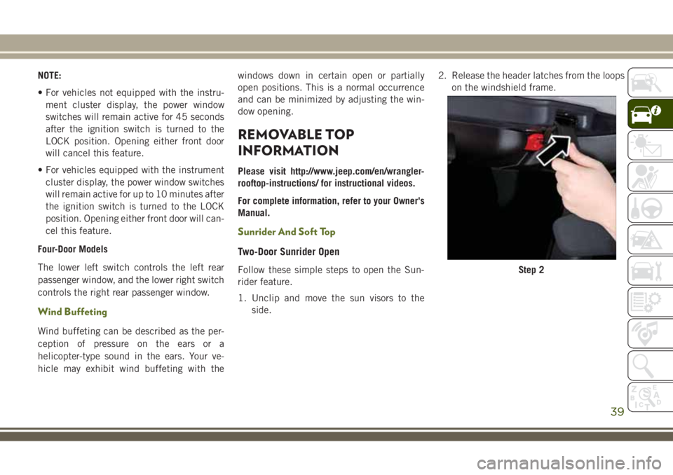
Two-Door Sunrider Open
Follow these simple steps to open the Sun-
rider feature.
1. Unclip and move the sun visors to the
side.2. Release the header latches from the loops
on the windshield frame.Step 2
39
Page 58 of 276
INSTRUMENT CLUSTER
DISPLAY — IF EQUIPPED
Your vehicle may be equipped with an instru-
ment cluster display, which offers useful in-
formation to the driver. With the ignition in
the STOP/OFF mode, opening/closing of a
door will activate the display for viewing, and
display the total miles, or kilometers, in the
odometer. Your instrument cluster display is
designed to display important information
about your vehicle’s systems and features.
Using a driver interactive display located on
the instrument panel, your instrument clus-
ter display can show you how systems are
working and give you warnings when they
aren’t. The steering wheel mounted controls
allow you to scroll through and enter the main
menus and submenus. You can access the
specific information you want and make se-
lections and adjustments.
Instrument Cluster Display Location And
Controls
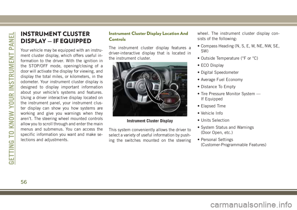
The instrument cluster display features a
driver-interactive display that is located in
the instrument cluster.
This system conveniently allows the driver to
select a variety of useful information by push-
ing the switches mounted on the steeringwheel. The instrument cluster display con-
sists of the following:
• Compass Heading (N, S, E, W, NE, NW, SE,
SW)
• Outside Temperature (°F or °C)
• ECO Display
• Digital Speedometer
• Average Fuel Economy
• Distance To Empty
• Tire Pressure Monitor System —
If Equipped
• Elapsed Time
• Vehicle Info
• Units Selection
• System Status and Warnings
(Door Open, etc.)
• Personal Settings
(Customer-Programmable Features)
Instrument Cluster Display
GETTING TO KNOW YOUR INSTRUMENT PANEL
56
Page 60 of 276
• Check Gascap (refer to “Refueling The Ve-
hicle” in “Starting And Operating” for fur-
ther information)
• Oil Change Required (with a single chime)
• ECO (Fuel Saver Indicator) — if equipped
Gear Shift Indicator (GSI) — If Equipped
The Gear Shift Indicator (GSI) system is en-
abled on vehicles with a manual transmis-
sion, or when a vehicle with an automatic
transmission is in manual shift mode. The
GSI provides the driver with a visual indica-
tion when the recommended gear shift point
has been reached. This indication notifies
the driver that changing gear will allow a
reduction in fuel consumption. When the up
shift indicator is shown on the display, the
GSI is advising the driver to engage a higher
gear. When the down shift indicator is shown
on the display, the GSI is advising the driver
to engage a lower gear.
The GSI indicator remains illuminated until
the driver changes gear, or the driving condi-
tions return to a situation where changing gear
is not required to improve fuel consumption.
Oil Change Required
Your vehicle is equipped with an engine oil
change indicator system. The “Oil Change
Required” message will display in the instru-
ment cluster display for approximately
10 seconds after a single chime has sounded
to indicate the next scheduled oil change
interval. The engine oil change indicator sys-
tem is duty cycle based, which means the
engine oil change interval may fluctuate de-
pendent upon your personal driving style.
Unless reset, this message will continue to
display each time you turn the ignition switch
to the ON position. To turn off the message
temporarily, push and release theMENUbut-
ton. To reset the oil change indicator system
(after performing the scheduled mainte-
nance), perform the following procedure:
WARNING LIGHTS AND
MESSAGES
The warning/indicator lights will illuminate in
the instrument panel together with a dedi-
cated message and/or acoustic signal when
applicable. These indications are indicativeand precautionary and as such must not be
considered as exhaustive and/or alternative
to the information contained in the Owner’s
Manual, which you are advised to read care-
fully in all cases. Always refer to the informa-
tion in this chapter in the event of a failure
indication. All active telltales will display first
if applicable. The system check menu may
appear different based upon equipment op-
tions and current vehicle status. Some tell-
tales are optional and may not appear.
Red Warning Lights
— Air Bag Warning Light
This light indicates a fault with the air bag,
and will turn on for four to eight seconds as a
bulb check when the ignition is placed in the
ON/RUN or ACC/ON/RUN position. This light
will illuminate with a single chime when a
fault with the air bag has been detected, it
will stay on until the fault is cleared. If the
light is either not on during startup, stays on,
or turns on while driving, have the system
inspected at an authorized dealer as soon as
possible.
GETTING TO KNOW YOUR INSTRUMENT PANEL
58
Page 66 of 276
— 4WD Indicator Light — If Equipped
This light alerts the driver that the vehicle is
in the four-wheel drive mode, and the front
and rear driveshafts are mechanically locked
together forcing the front and rear wheels to
rotate at the same speed.
— Sway Bar Indicator Light — If
Equipped
This indicator will illuminate when the front
sway bar is disconnected.
Green Indicator Lights
— Front Fog Indicator Light — If
Equipped
This indicator will illuminate when the front
fog lights are on.
— Turn Signal Indicator Lights
When the left or right turn signal is activated,
the turn signal indicator will flash indepen-
dently and the corresponding exterior turn
signal lamps will flash. Turn signals can be
activated when the multifunction lever is
moved down (left) or up (right).NOTE:
• A continuous chime will sound if the ve-
hicle is driven more than 1 mile (1.6 km)
with either turn signal on.
• Check for an inoperative outside light bulb
if either indicator flashes at a rapid rate.
White Indicator Lights
CRUISE— Cruise Indicator
This indicator shows that the Speed Control
System is ON.
— Hill Descent Control (HDC) Indicator
Light — If Equipped
This indicator shows when the Hill Descent
Control (HDC) feature is turned on. The lamp
will be on solid when HDC is armed. HDC can
only be armed when the transfer case is in the
“4WD LOW” position and the vehicle speed
is less then 30 mph (48 km/h). If these
conditions are not met while attempting to
use the HDC feature, the HDC indicator light
will flash on/off.
Blue Indicator Lights
— High Beam Indicator Light
This indicator shows that the high beam
headlights are on. With the low beams acti-
vated, push the multifunction lever forward
(toward the front of the vehicle) to turn on the
high beams. Pull the multifunction lever rear-
ward (toward the rear of the vehicle) to turn
off the high beams. If the high beams are off,
pull the lever toward you for a temporary high
beam on, "flash to pass" scenario.
ONBOARD DIAGNOSTIC
SYSTEM — OBD II
Your vehicle is equipped with a sophisticated
Onboard Diagnostic system called OBD II.
This system monitors the performance of the
emissions, engine, and automatic transmis-
sion control systems. When these systems are
operating properly, your vehicle will provide
excellent performance and fuel economy, as
well as engine emissions well within current
government regulations.
GETTING TO KNOW YOUR INSTRUMENT PANEL
64