traction control JEEP WRANGLER 2021 Owner handbook (in English)
[x] Cancel search | Manufacturer: JEEP, Model Year: 2021, Model line: WRANGLER, Model: JEEP WRANGLER 2021Pages: 276, PDF Size: 4.47 MB
Page 70 of 276
SAFETY FEATURES
Anti-Lock Brake System (ABS)
The Anti-Lock Brake System (ABS) provides
increased vehicle stability and brake perfor-
mance under most braking conditions. The
system automatically prevents wheel lock,
and enhances vehicle control during braking.
The ABS performs a self-check cycle to en-
sure that the ABS is working properly each
time the vehicle is started and driven. During
this self-check, you may hear a slight clicking
sound as well as some related motor noises.
ABS is activated during braking when the
system detects one or more wheels begin to
lock. Road conditions such as ice, snow,
gravel, bumps, railroad tracks, loose debris,
or panic stops may increase the likelihood of
ABS activation(s).
You also may experience the following when
ABS activates:
• The ABS motor noise (it may continue to
run for a short time after the stop).
• The clicking sound of solenoid valves.• Brake pedal pulsations.
• A slight drop of the brake pedal at the end
of the stop.
These are all normal characteristics of ABS.
WARNING!
• The ABS contains sophisticated elec-
tronic equipment that may be suscep-
tible to interference caused by improp-
erly installed or high output radio
transmitting equipment. This interfer-
ence can cause possible loss of anti-lock
braking capability. Installation of such
equipment should be performed by
qualified professionals.
• Pumping of the Anti-Lock Brakes will
diminish their effectiveness and may
lead to a collision. Pumping makes the
stopping distance longer. Just press
firmly on your brake pedal when you
need to slow down or stop.
• The ABS cannot prevent the natural laws
of physics from acting on the vehicle,
nor can it increase braking or steering
efficiency beyond that afforded by the
WARNING!
condition of the vehicle brakes and tires
or the traction afforded.
• The ABS cannot prevent collisions, in-
cluding those resulting from excessive
speed in turns, following another vehicle
too closely, or hydroplaning.
• The capabilities of an ABS equipped
vehicle must never be exploited in a
reckless or dangerous manner that could
jeopardize the user’s safety or the safety
of others.
ABS is designed to function with the OEM
tires. Modification may result in degraded
ABS performance.
Anti-Lock Brake Warning Light
The yellow “Anti-Lock Brake Warning Light”
will turn on when the ignition is turned to the
ON/RUN mode and may stay on for as long as
four seconds.
If the “Anti-Lock Brake Warning Light” re-
mains on or comes on while driving, it indi-
cates that the anti-lock portion of the brake
system is not functioning and that service is
SAFETY
68
Page 71 of 276
required. However, the conventional brake
system will continue to operate normally if
the “Brake System Warning Light” is not on.
If the “Anti-Lock Brake Warning Light” is on,
the brake system should be serviced as soon
as possible to restore the benefits of anti-lock
brakes. If the “Anti-Lock Brake Warning
Light” does not come on when the ignition is
turned to the ON/RUN mode, have the light
repaired as soon as possible.
Electronic Brake Control System
Your vehicle is equipped with an advanced
Electronic Brake Control system (EBC). This
system includes Electronic Brake Force Dis-
tribution (EBD), Brake Assist System (BAS),
Hill Start Assist (HSA), Traction Control Sys-
tem (TCS), Electronic Stability Control
(ESC), and Electronic Roll Mitigation (ERM).
These systems work together to enhance both
vehicle stability and control in various driving
conditions.
Your vehicle may also be equipped with
Trailer Sway Control (TSC) and Hill Descent
Control (HDC).
Electronic Brake Force Distribution (EBD)
This function manages the distribution of the
braking torque between the front and rear
axles by limiting braking pressure to the rear
axle. This is done to prevent overslip of the
rear wheels to avoid vehicle instability, and to
prevent the rear axle from entering ABS be-
fore the front axle.
Brake System Warning Light
The red “Brake System Warning Light” will
turn on when the ignition is turned to the
ON/RUN mode and may stay on for as long as
four seconds.
If the “Brake System Warning Light” remains
on or comes on while driving, it indicates that
the brake system is not functioning properly
and that immediate service is required. If the
“Brake System Warning Light” does not
come on when the ignition is turned to the
ON/RUN mode, have the light repaired as
soon as possible.
Brake Assist System (BAS)
The BAS is designed to optimize the vehicle’s
braking capability during emergency braking
maneuvers. The system detects an emer-
gency braking situation by sensing the rate
and amount of brake application and then
applies optimum pressure to the brakes. This
can help reduce braking distances. The BAS
complements the anti-lock brake system
(ABS). Applying the brakes very quickly re-
sults in the best BAS assistance. To receive
the benefit of the system, you must apply
continuous braking pressure during the stop-
ping sequence, (do not “pump” the brakes).
Do not reduce brake pedal pressure unless
braking is no longer desired. Once the brake
pedal is released, the BAS is deactivated.
WARNING!
The Brake Assist System (BAS) cannot
prevent the natural laws of physics from
acting on the vehicle, nor can it increase
the traction afforded by prevailing road
conditions. BAS cannot prevent collisions,
including those resulting from excessive
69
Page 73 of 276
6. Push the “ESC Off” button located in the
lower switch bank below the climate con-
trol four times within 20 seconds. The
“ESC Off Indicator Light” should turn on
and turn off two times.
7. Rotate the steering wheel back to center
and then an additional slightly more than
one-half turn to the right.
8. Turn the ignition to the OFF mode and
then back to ON. If the sequence was
completed properly, the “ESC Off Indica-
tor Light” will blink several times to con-
firm HSA is disabled.
9. Repeat these steps if you want to return
this feature to its previous setting.
Traction Control System (TCS)
This system monitors the amount of wheel
spin of each of the driven wheels. If wheel
spin is detected, the TCS may apply brake
pressure to the spinning wheel(s) and/or re-
duce engine power to provide enhanced ac-
celeration and stability. A feature of the TCS,
Brake Limited Differential (BLD), functions
similar to a limited slip differential and con-
trols the wheel spin across a driven axle. Ifone wheel on a driven axle is spinning faster
than the other, the system will apply the
brake of the spinning wheel. This will allow
more engine torque to be applied to the wheel
that is not spinning. BLD may remain en-
abled even if TCS and ESC are in a reduced
mode.
Electronic Stability Control (ESC)
This system enhances directional control and
stability of the vehicle under various driving
conditions. The ESC corrects for over/under
steering of the vehicle by applying the brake
of the appropriate wheel to assist in counter-
acting the over/under steer condition. Engine
power may also be reduced to help the ve-
hicle maintain the desired path.
ESC uses sensors in the vehicle to determine
the vehicle path intended by the driver and
compares it to the actual path of the vehicle.
When the actual path does not match the
intended path, ESC applies the brake of the
appropriate wheel to assist in counteracting
the oversteer or understeer condition.
• Oversteer - when the vehicle is turning more
than appropriate for the steering wheel po-
sition.• Understeer - when the vehicle is turning
less than appropriate for the steering wheel
position.
The “ESC Activation/Malfunction Indicator
Light” (located in the instrument cluster),
starts to flash as soon as the tires lose trac-
tion and the ESC system becomes active. The
“ESC Activation/Malfunction Indicator
Light” also flashes when TCS is active. If the
“ESC Activation/Malfunction Indicator
Light” begins to flash during acceleration,
ease up on the accelerator and apply as little
throttle as possible. Be sure to adapt your
speed and driving to the prevailing road
conditions.
WARNING!
• Electronic Stability Control (ESC) can-
not prevent the natural laws of physics
from acting on the vehicle, nor can it
increase the traction afforded by prevail-
ing road conditions. ESC cannot prevent
accidents, including those resulting
from excessive speed in turns, driving on
very slippery surfaces, or hydroplaning.
71
Page 74 of 276
WARNING!
ESC also cannot prevent accidents re-
sulting from loss of vehicle control due
to inappropriate driver input for the con-
ditions. Only a safe, attentive, and skill-
ful driver can prevent accidents. The
capabilities of an ESC equipped vehicle
must never be exploited in a reckless or
dangerous manner which could jeopar-
dize the user’s safety or the safety of
others.
• Vehicle modifications, or failure to prop-
erly maintain your vehicle, may change
the handling characteristics of your ve-
hicle, and may negatively affect the per-
formance of the ESC system. Changes to
the steering system, suspension, brak-
ing system, tire type and size or wheel
size may adversely affect ESC perfor-
mance. Improperly inflated and un-
evenly worn tires may also degrade ESC
performance. Any vehicle modification
or poor vehicle maintenance that re-
duces the effectiveness of the ESC sys-
tem can increase the risk of loss of
WARNING!
vehicle control, vehicle rollover, per-
sonal injury and death.
The ESC system has three available operating
modes in 4H range. The system has one
operating mode in 4L range. Two-wheel drive
vehicles and four-wheel drive vehicles in 2H
range have two operating modes.
4H Range (4WD Models)
ESC On
This is the normal operating mode for ESC in
4H range.
ESC Partial Off
This mode is entered by momentarily pushing
the ESC OFF switch. When in "ESC Partial
Off" mode, the TCS portion of ESC (except for
the limited slip feature described in the TCS
section), has been disabled and the "ESC Off
Indicator Light" will be illuminated.
This mode is intended to be used if the
vehicle is in deep snow, sand, or gravel con-
ditions and more wheel spin than ESC would
normally allow is required to gain traction. Toturn ESC on again, momentarily push the
ESC OFF switch. This will restore the normal
“ESC On” mode of operation.
NOTE:
To improve the vehicle’s traction when driving
with snow chains, or starting off in deep
snow, sand, or gravel, it may be desirable to
switch to the "ESC Partial Off" mode by
pushing the ESC OFF switch. Once the situ-
ation requiring ESC to be switched to the
"ESC Partial Off" mode is overcome, turn ESC
back on by momentarily pushing the ESC
OFF switch. This may be done while the
vehicle is in motion.
WARNING!
• When in "ESC Partial Off" mode, the TCS
functionality of ESC, (except for the lim-
ited slip feature described in the TCS
section), has been disabled and the
“ESC Off Indicator Light” will be illumi-
nated. When in "ESC Partial Off" mode,
the engine power reduction feature of
TCS is disabled, and the enhanced ve-
SAFETY
72
Page 77 of 276
WARNING!
• Trailer Sway Control (TSC) is disabled
when the ESC system is in the "Partial
Off" mode.
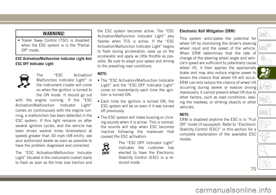
ESC Activation/Malfunction Indicator Light And
ESC OFF Indicator Light
The “ESC Activation/
Malfunction Indicator Light” in
the instrument cluster will come
on when the ignition is turned to
the ON mode. It should go out
with the engine running. If the “ESC
Activation/Malfunction Indicator Light”
comes on continuously with the engine run-
ning, a malfunction has been detected in the
ESC system. If this light remains on after
several ignition cycles, and the vehicle has
been driven several miles (kilometers) at
speeds greater than 30 mph (48 km/h), see
your authorized dealer as soon as possible to
have the problem diagnosed and corrected.
The “ESC Activation/Malfunction Indicator
Light” (located in the instrument cluster) starts
to flash as soon as the tires lose traction andthe ESC system becomes active. The “ESC
Activation/Malfunction Indicator Light” also
flashes when TCS is active. If the “ESC
Activation/Malfunction Indicator Light” begins
to flash during acceleration, ease up on the
accelerator and apply as little throttle as pos-
sible. Be sure to adapt your speed and driving
to the prevailing road conditions.
NOTE:
• The “ESC Activation/Malfunction Indicator
Light” and the “ESC OFF Indicator Light”
come on momentarily each time the igni-
tion is turned ON.
• Each time the ignition is turned ON, the
ESC system will be on even if it was turned
off previously.
• The ESC system will make buzzing or click-
ing sounds when it is active. This is normal;
the sounds will stop when ESC becomes
inactive following the maneuver that
caused the ESC activation.
The “ESC OFF Indicator Light”
indicates the customer has
elected to have the Electronic
Stability Control (ESC) in a re-
duced mode.
Electronic Roll Mitigation (ERM)
This system anticipates the potential for
wheel lift by monitoring the driver’s steering
wheel input and the speed of the vehicle.
When ERM determines that the rate of
change of the steering wheel angle and vehi-
cle’s speed are sufficient to potentially cause
wheel lift, it then applies the appropriate
brake and may also reduce engine power to
lessen the chance that wheel lift will occur.
ERM can only reduce the chance of wheel lift
occurring during severe or evasive driving
maneuvers; it cannot prevent wheel lift due to
other factors, such as road conditions, leav-
ing the roadway, or striking objects or other
vehicles.
NOTE:
ERM is disabled anytime the ESC is in “Full
Off” mode (if equipped). Refer to “Electronic
Stability Control (ESC)” in this section for a
complete explanation of the available ESC
modes.
75
Page 131 of 276
• The system will ignore attempts to upshift
at too low of a vehicle speed.
• Avoid using speed control when AutoStick
is engaged.
• Transmission shifting will be more notice-
able when AutoStick is enabled.
NOTE:
When the transfer case is in the 4L (Low)
range, the transmission will shift automati-
cally (but no higher than the displayed gear).
To disengage AutoStick mode, hold the gear
selector to the right (+) until "D" is once again
displayed in the instrument cluster. You can
shift in or out of the AutoStick mode at any
time without taking your foot off the accelera-
tor pedal.
WARNING!
Do not downshift for additional engine
braking on a slippery surface. The drive
wheels could lose their grip and the ve-
hicle could skid, causing a collision or
personal injury.
FOUR–WHEEL DRIVE
OPERATION (COMMAND-
TRAC I OR ROCK-TRAC)
WARNING!
Failure to engage a transfer case position
completely can cause transfer case dam-
age or loss of power and vehicle control.
You could have a collision. Do not drive the
vehicle unless the transfer case is fully
engaged.
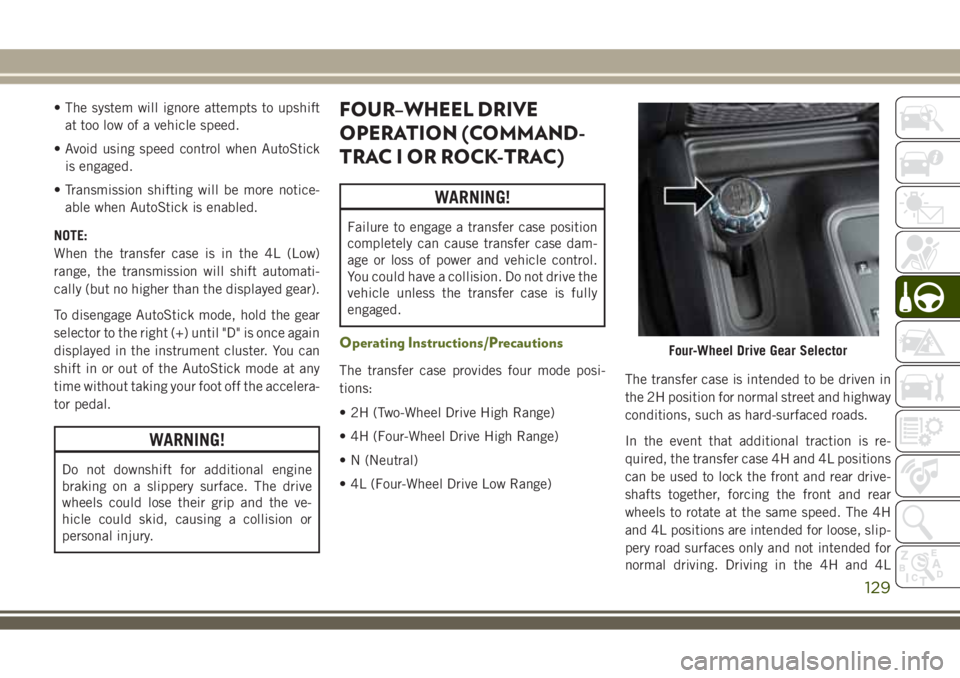
Operating Instructions/Precautions
The transfer case provides four mode posi-
tions:
• 2H (Two-Wheel Drive High Range)
• 4H (Four-Wheel Drive High Range)
• N (Neutral)
• 4L (Four-Wheel Drive Low Range)The transfer case is intended to be driven in
the 2H position for normal street and highway
conditions, such as hard-surfaced roads.
In the event that additional traction is re-
quired, the transfer case 4H and 4L positions
can be used to lock the front and rear drive-
shafts together, forcing the front and rear
wheels to rotate at the same speed. The 4H
and 4L positions are intended for loose, slip-
pery road surfaces only and not intended for
normal driving. Driving in the 4H and 4L
Four-Wheel Drive Gear Selector
129
Page 134 of 276
NOTE:
Shifting into or out of 4L is possible with the
vehicle completely stopped; however, diffi-
culty may occur due to the mating teeth not
being properly aligned. Several attempts may
be required for clutch teeth alignment and
shift completion to occur. The preferred
method is with the vehicle rolling at 2 to
3 mph (3 to 5 km/h). Avoid attempting to
engage or disengage 4L with the vehicle
moving faster than 2 to 3 mph (3 to 5 km/h).
WARNING!
Failure to engage a transfer case position
completely can cause transfer case dam-
age or loss of power and vehicle control.
You could have a collision. Do not drive the
vehicle unless the transfer case is fully
engaged.
Trac-Lok Rear Axle — If Equipped
The Trac-Lok rear axle provides a constant
driving force to both rear wheels and reduces
wheel spin caused by the loss of traction at
one driving wheel. If traction differs between
the two rear wheels, the differential auto-
matically proportions the usable torque by
providing more torque to the wheel that has
traction.
Trac-Lok is especially helpful during slippery
driving conditions. With both rear wheels on a
slippery surface, a slight application of the
accelerator will supply maximum traction.
WARNING!
On vehicles equipped with a limited-slip
differential, never run the engine with one
rear wheel off the ground. The vehicle may
drive through the rear wheel remaining on
the ground and cause you to lose control of
your vehicle.
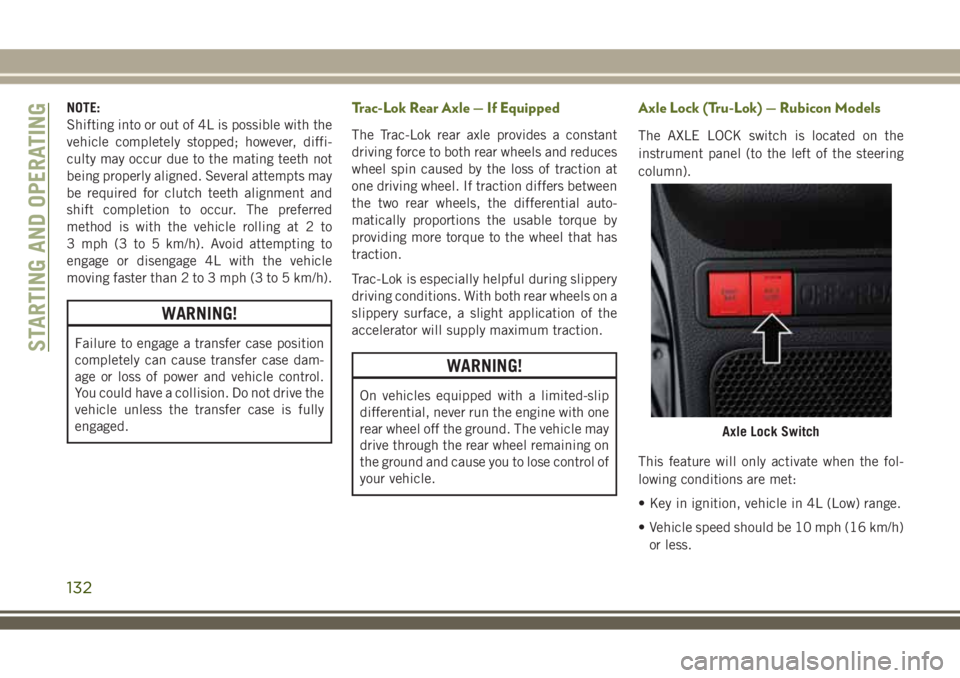
Axle Lock (Tru-Lok) — Rubicon Models
The AXLE LOCK switch is located on the
instrument panel (to the left of the steering
column).
This feature will only activate when the fol-
lowing conditions are met:
• Key in ignition, vehicle in 4L (Low) range.
• Vehicle speed should be 10 mph (16 km/h)
or less.
Axle Lock Switch
STARTING AND OPERATING
132
Page 199 of 276
WARNING!
resulting in serious injury or death. Use
only the tire and wheel sizes with load
ratings approved for your vehicle.
• Never use a tire with a smaller load index
or capacity, other than what was origi-
nally equipped on your vehicle. Using a
tire with a smaller load index could re-
sult in tire overloading and failure. You
could lose control and have a collision.
• Failure to equip your vehicle with tires
having adequate speed capability can
result in sudden tire failure and loss of
vehicle control.
CAUTION!
Replacing original tires with tires of a
different size may result in false speedom-
eter and odometer readings.
Tire Types
All Season Tires — If Equipped
All Season tires provide traction for all sea-
sons (Spring, Summer, Fall, and Winter).
Traction levels may vary between different all
season tires. All season tires can be identified
by the M+S, M&S, M/S or MS designation on
the tire sidewall. Use all season tires only in
sets of four; failure to do so may adversely
affect the safety and handling of your vehicle.
Summer Or Three Season Tires — If
Equipped
Summer tires provide traction in both wet
and dry conditions, and are not intended to
be driven in snow or on ice. If your vehicle is
equipped with Summer tires, be aware these
tires are not designed for Winter or cold
driving conditions. Install Winter tires on your
vehicle when ambient temperatures are less
than 40°F (5°C) or if roads are covered with
ice or snow. For more information, contact an
authorized dealer.
Summer tires do not contain the all season
designation or mountain/snowflake symbol
on the tire sidewall. Use Summer tires only insets of four; failure to do so may adversely
affect the safety and handling of your vehicle.
WARNING!
Do not use Summer tires in snow/ice con-
ditions. You could lose vehicle control,
resulting in severe injury or death. Driving
too fast for conditions also creates the
possibility of loss of vehicle control.
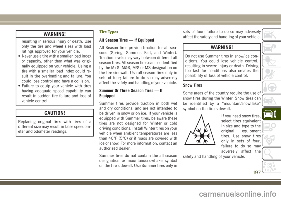
Snow Tires
Some areas of the country require the use of
snow tires during the Winter. Snow tires can
be identified by a “mountain/snowflake”
symbol on the tire sidewall.
If you need snow tires,
select tires equivalent
in size and type to the
original equipment
tires. Use snow tires
only in sets of four;
failure to do so may
adversely affect the
safety and handling of your vehicle.
197
Page 202 of 276
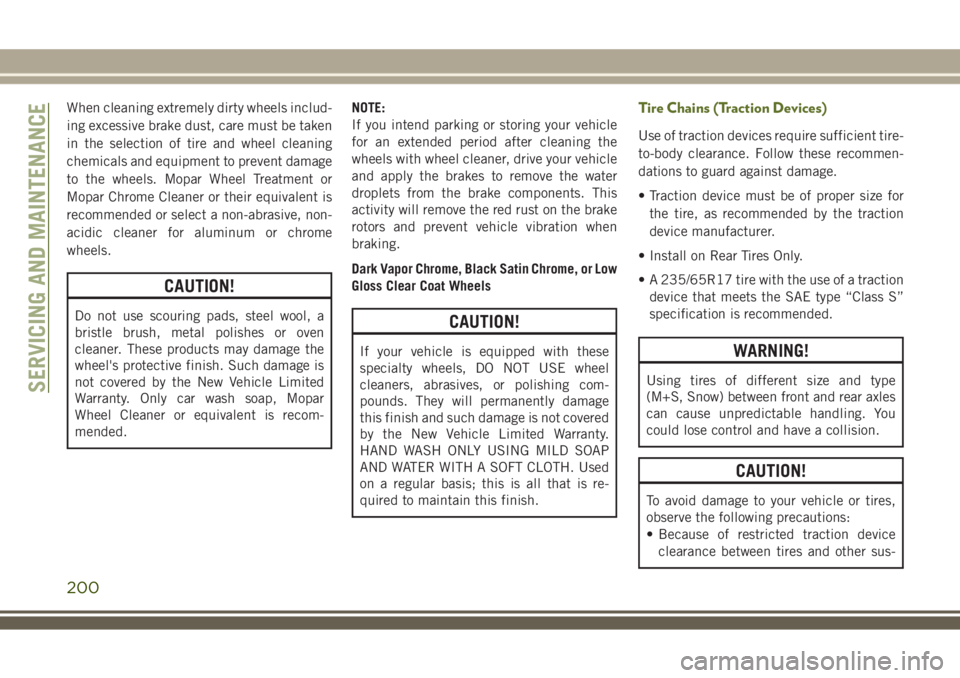
When cleaning extremely dirty wheels includ-
ing excessive brake dust, care must be taken
in the selection of tire and wheel cleaning
chemicals and equipment to prevent damage
to the wheels. Mopar Wheel Treatment or
Mopar Chrome Cleaner or their equivalent is
recommended or select a non-abrasive, non-
acidic cleaner for aluminum or chrome
wheels.
CAUTION!
Do not use scouring pads, steel wool, a
bristle brush, metal polishes or oven
cleaner. These products may damage the
wheel's protective finish. Such damage is
not covered by the New Vehicle Limited
Warranty. Only car wash soap, Mopar
Wheel Cleaner or equivalent is recom-
mended.NOTE:
If you intend parking or storing your vehicle
for an extended period after cleaning the
wheels with wheel cleaner, drive your vehicle
and apply the brakes to remove the water
droplets from the brake components. This
activity will remove the red rust on the brake
rotors and prevent vehicle vibration when
braking.
Dark Vapor Chrome, Black Satin Chrome, or Low
Gloss Clear Coat WheelsCAUTION!
If your vehicle is equipped with these
specialty wheels, DO NOT USE wheel
cleaners, abrasives, or polishing com-
pounds. They will permanently damage
this finish and such damage is not covered
by the New Vehicle Limited Warranty.
HAND WASH ONLY USING MILD SOAP
AND WATER WITH A SOFT CLOTH. Used
on a regular basis; this is all that is re-
quired to maintain this finish.
Tire Chains (Traction Devices)
Use of traction devices require sufficient tire-
to-body clearance. Follow these recommen-
dations to guard against damage.
• Traction device must be of proper size for
the tire, as recommended by the traction
device manufacturer.
• Install on Rear Tires Only.
• A 235/65R17 tire with the use of a traction
device that meets the SAE type “Class S”
specification is recommended.
WARNING!
Using tires of different size and type
(M+S, Snow) between front and rear axles
can cause unpredictable handling. You
could lose control and have a collision.
CAUTION!
To avoid damage to your vehicle or tires,
observe the following precautions:
• Because of restricted traction device
clearance between tires and other sus-
SERVICING AND MAINTENANCE
200
Page 262 of 276
Cold Weather Operation..........117
Compact Spare Tire.............198
Connector
UCI ....................233
Universal Consumer Interface
(UCI)...................233
Cooling System...............182
Coolant Capacity............210
Inspection................182
Selection Of Coolant (Antifreeze) . .210
Customer Assistance............242
Daytime Running Lights...........29
Dealer Service................189
Defroster, Windshield............113
Delay (Intermittent) Wipers.........31
Diagnostic System, Onboard........64
Diesel Engine Maintenance........175
Diesel Fuel..................209
Diesel Fuel Requirements.........209
Dimmer Switch, Headlight.........29
Dipsticks
Oil (Engine)...............182
Disabled Vehicle Towing..........165
Disarming, Security System.........18
Doors......................19Driver's Seat Back Tilt............21
Electronic Brake Control System......69
Anti-Lock Brake System........68
Electronic Roll Mitigation.......75
Traction Control System........71
Electronic Speed Control (Cruise
Control)..................136
Electronic Stability Control (ESC).....71
Electronic Throttle Control Warning
Light.....................60
Emergency Brake..............121
Emergency, In Case Of
Jacking..............154, 192
Jump Starting..............160
Engine.....................180
Break-In Recommendations.....121
Compartment...........180, 181
Compartment Identification . .180, 181
Cooling.................
.182
Exhaust Gas Caution..........112
Fails To Start...............118
Flooded, Starting............118
Fuel Requirements...........210
Jump Starting..............160
Oil .....................210
Oil Change Interval...........58Oil Filler Cap..............180
Oil Selection..............210
Overheating...............163
Starting.................117
Enhanced Accident Response
Feature................98, 168
Exhaust Gas Caution............112
Exhaust System...............112
Exterior Lights.............28, 114
Fabric Care..................203
Fabric Top..................203
Filters
Air Conditioning..........38, 187
Flashers
Hazard Warning.............146
Turn Signal......64, 114, 148, 149
Flash-To-Pass.................29
Flooded Engine Starting..........118
Fluid, Brake.................211
Fluid Capacities...............210
Fluid Leaks..................114
Fluid Level Checks
Brake...................183
Engine Oil................182
Manual Transmission.........184
Fluids And Lubricants...........210
INDEX
260