traction control JEEP WRANGLER 2023 User Guide
[x] Cancel search | Manufacturer: JEEP, Model Year: 2023, Model line: WRANGLER, Model: JEEP WRANGLER 2023Pages: 396, PDF Size: 25.15 MB
Page 246 of 396
244
SAFETY
SAFETY FEATURES
ANTI-LOCK BRAKE SYSTEM (ABS)
The ABS provides increased vehicle stability and brake
performance under most braking conditions. The system
automatically prevents wheel lock and enhances vehicle
control during braking.
The ABS performs a self-check cycle to ensure that the
ABS is working properly each time the vehicle is started
and driven. During this self-check, you may hear a slight
clicking sound as well as some related motor noises.
The ABS is activated during braking when the system
detects one or more wheels are beginning to lock. Road
conditions such as ice, snow, gravel, bumps, railroad
tracks, loose debris, or panic stops may increase the
likelihood of ABS activation(s).
You also may experience the following normal
characteristics when the ABS activates:
ABS motor noise or clicking sounds (you may continue
to hear for a short time after the stop)
Brake pedal pulsations
A slight drop of the brake pedal at the end of the stop
The ABS is designed to function with the Original
Equipment Manufacturer (OEM) tires. Modification may
result in degraded ABS performance.
Anti-Lock Brake System (ABS) Warning
Light
The yellow ABS Warning Light will turn on when the ignition
is placed in the ON/RUN mode and may stay on for as long
as four seconds.
If the ABS Warning Light remains on or comes on while
driving, it indicates that the anti-lock portion of the brake
system is not functioning and that service is required.
However, the conventional brake system will continue to
operate normally if the ABS Warning Light is on.
If the ABS Warning Light is on, the brake system should be
serviced as soon as possible to restore the benefits of
Anti-Lock Brakes. If the ABS Warning Light does not come
on when the ignition is placed in the ON/RUN mode, have
the light repaired as soon as possible.
REAR SEAT REMINDER ALERT (RSRA) —
I
F EQUIPPED
RSRA alerts you through a visual and auditory notification
of the possible presence of an object, passenger, or pet in
the rear seats if a rear door was opened up to 10 minutes
before the ignition was placed in the ON/RUN position.
RSRA does not directly detect objects, passengers, or pets
in the rear seats. When the previous conditions are met,
RSRA displays the message “Check Rear Seat” on the
instrument cluster display and sounds an auditory alert
upon the driver placing the ignition in the OFF position to
exit the vehicle.
WARNING!
The ABS contains sophisticated electronic equip -
ment that may be susceptible to interference caused
by improperly installed or high output radio transmit -
ting equipment. This interference can cause possible
loss of anti-lock braking capability. Installation of
such equipment should be performed by qualified
professionals.
Pumping of the Anti-Lock Brakes will diminish their
effectiveness and may lead to a collision. Pumping
makes the stopping distance longer. Just press firmly
on your brake pedal when you need to slow down or
stop.
The ABS cannot prevent the natural laws of physics
from acting on the vehicle, nor can it increase
braking or steering efficiency beyond that afforded
by the condition of the vehicle brakes and tires or the
traction afforded.
The ABS cannot prevent collisions, including those
resulting from excessive speed in turns, following
another vehicle too closely, or hydroplaning.
The capabilities of an ABS equipped vehicle must
never be exploited in a reckless or dangerous
manner that could jeopardize the user’s safety or the
safety of others.
23_JL_OM_EN_USC_t.book Page 244
Page 247 of 396
SAFETY245
To enable or disable RSRA, see Úpage 184.
ELECTRONIC BRAKE CONTROL (EBC)
S
YSTEM
If applicable, refer to the “Hybrid Supplement” for
additional information.
Your vehicle is equipped with an advanced Electronic
Brake Control (EBC) system. This system includes
Anti-Lock Brake System (ABS), Brake Assist System (BAS),
Electronic Brake Force Distribution (EBD), Electronic Roll
Mitigation (ERM), Electronic Stability Control (ESC), Hill
Start Assist (HSA), and Traction Control System (TCS). These systems work together to enhance both vehicle
stability and control in various driving conditions.
Your vehicle may also be equipped with Hill Descent
Control (HDC), Rain Brake Support (RBS), Ready Alert
Braking (RAB), and Trailer Sway Control (TSC).
Brake System Warning Light
The red Brake System Warning Light will turn on when the
ignition is placed in the ON/RUN mode and may stay on for
as long as four seconds.
If the Brake System Warning Light remains on or comes on
while driving, it indicates that the brake system is not
functioning properly and that immediate service is
required. If the Brake System Warning Light does not
come on when the ignition is placed in the ON/RUN mode,
have the light repaired as soon as possible.
Brake Assist System (BAS)
The BAS is designed to optimize the vehicle’s braking
capability during emergency braking maneuvers. The
system detects an emergency braking situation by sensing
the rate and amount of brake application and then applies
optimum pressure to the brakes. This can help reduce
braking distances. The BAS complements the Anti-Lock
Brake System (ABS). Applying the brakes very quickly
results in the best BAS assistance. To receive the benefit
of the system, you must apply continuous braking
pressure during the stopping sequence (do not “pump”
the brakes). Do not reduce brake pedal pressure unless
braking is no longer desired. Once the brake pedal is
released, the BAS is deactivated.
Electronic Brake Force Distribution (EBD)
EBD manages the distribution of the braking torque
between the front and rear axles by limiting braking
pressure to the rear axle. This is done to prevent overslip
of the rear wheels to avoid vehicle instability, and to
prevent the rear axle from entering ABS before the front
axle.
Electronic Roll Mitigation (ERM)
ERM anticipates the potential for wheel lift by monitoring
the driver’s steering wheel input and the speed of the
vehicle. When ERM determines that the rate of change of
the steering wheel angle and vehicle’s speed are
sufficient to potentially cause wheel lift, it then applies the
appropriate brake and may also reduce engine power to
lessen the chance that wheel lift will occur. ERM can only
reduce the chance of wheel lift occurring during severe or
evasive driving maneuvers; it cannot prevent wheel lift
due to other factors, such as road conditions, leaving the
roadway, or striking objects or other vehicles.
WARNING!
Before exiting a vehicle, always come to a complete
stop, then shift the automatic transmission into
PARK and apply the parking brake.
Always make sure the keyless ignition node is in the
OFF position, key fob is removed from the vehicle
and vehicle is locked.
Never leave children alone in a vehicle, or with
access to an unlocked vehicle. Leaving children in a
vehicle unattended is dangerous for a number of
reasons. A child or others could be seriously or fatally
injured. Children should be warned not to touch the
parking brake, brake pedal or the gear selector.
Do not leave children or animals inside parked vehi -
cles in hot weather. Interior heat buildup may cause
serious injury or death.
WARNING!
The Brake Assist System (BAS) cannot prevent the natu -
ral laws of physics from acting on the vehicle, nor can it
increase the traction afforded by prevailing road condi -
tions. BAS cannot prevent collisions, including those
resulting from excessive speed in turns, driving on very
slippery surfaces, or hydroplaning. The capabilities of a
BAS-equipped vehicle must never be exploited in a
reckless or dangerous manner, which could jeopardize
the user's safety or the safety of others.
6
23_JL_OM_EN_USC_t.book Page 245
Page 248 of 396
246SAFETY
(Continued)
NOTE:ERM is disabled any time the ESC is in “Full Off” mode (if
equipped) Úpage 246.
Electronic Stability Control (ESC)
ESC enhances directional control and stability of the
vehicle under various driving conditions. ESC corrects for
oversteering or understeering of the vehicle by applying
the brake of the appropriate wheel(s) to counteract these
conditions. Engine power may also be reduced to help the
vehicle maintain the desired path.
Oversteer — when the vehicle is turning more than
appropriate for the steering wheel position.
Understeer — when the vehicle is turning less than
appropriate for the steering wheel position.
ESC uses sensors in the vehicle to determine the vehicle
path intended by the driver and compares it to the actual
path of the vehicle. When the actual path does not match
the intended path, ESC applies the brake of the
appropriate wheel to assist in counteracting the oversteer
or understeer condition. The ESC Activation/Malfunction Indicator Light located in
the instrument cluster will start to flash as soon as the ESC
system becomes active. The ESC Activation/Malfunction
Indicator Light also flashes when the TCS is active. If the
ESC Activation/Malfunction Indicator Light begins to flash
during acceleration, ease up on the accelerator and apply
as little throttle as possible. Be sure to adapt your speed
and driving to the prevailing road conditions.
ESC Operating Modes
Depending upon model and mode of operation, the ESC
system may have multiple operating modes.
ESC On
“ESC On” is the normal operating mode for the ESC.
Whenever the vehicle is started, the ESC system will be in
this mode. This mode should be used for most driving
conditions. Alternate ESC modes should only be used for
specific reasons as noted in the following paragraphs.
Partial Off
This mode may be useful if the vehicle becomes stuck.
This mode may modify TCS and ESC thresholds for
activation, which allows for more wheel spin than normally
allowed.
WARNING!
Many factors, such as vehicle loading, road conditions
and driving conditions, influence the chance that wheel
lift or rollover may occur. ERM cannot prevent all wheel
lift or rollovers, especially those that involve leaving the
roadway or striking objects or other vehicles. The capa-
bilities of an ERM-equipped vehicle must never be
exploited in a reckless or dangerous manner which
could jeopardize the user's safety or the safety of oth
-
ers.
WARNING!
Electronic Stability Control (ESC) cannot prevent the
natural laws of physics from acting on the vehicle,
nor can it increase the traction afforded by prevailing
road conditions. ESC cannot prevent accidents,
including those resulting from excessive speed in
turns, driving on very slippery surfaces, or hydro -
planing. ESC also cannot prevent accidents resulting
from loss of vehicle control due to inappropriate
driver input for the conditions. Only a safe, attentive,
and skillful driver can prevent accidents. The capabil -
ities of an ESC equipped vehicle must never be
exploited in a reckless or dangerous manner which
could jeopardize the user’s safety or the safety of
others.
Vehicle modifications, or failure to properly maintain
your vehicle, may change the handling characteris -
tics of your vehicle, and may negatively affect the
performance of the ESC system. Changes to the
steering system, suspension, braking system, tire
type and size or wheel size may adversely affect ESC
performance. Improperly inflated and unevenly worn
tires may also degrade ESC performance. Any vehicle
modification or poor vehicle maintenance that
reduces the effectiveness of the ESC system can
increase the risk of loss of vehicle control, vehicle
rollover, personal injury and death.
WARNING!
23_JL_OM_EN_USC_t.book Page 246
Page 249 of 396
SAFETY247
To enter the “Partial Off” mode, momentarily push the ESC
OFF button and the ESC OFF Indicator Light will illuminate.
To turn the ESC on again, momentarily push the ESC OFF
button and the ESC OFF Indicator Light will turn off.
NOTE:For vehicles with multiple partial ESC modes, the push and
release of the button will toggle the ESC modes. Multiple
attempts may be required to return to “ESC On”.
Full Off — If Equipped
The “Full Off” mode is intended for off-highway or off-road
use only and should not be used on any public roadways.
In this mode, TCS and ESC features are turned off. To
enter the “Full Off” mode, push and hold the ESC OFF
button for five seconds while the vehicle is stopped with
the engine running. After five seconds, a chime will sound,
the ESC OFF Indicator Light will illuminate, and the “ESC
Off” message will display in the instrument cluster. To turn
ESC on again, momentarily push the ESC OFF button.
NOTE:System may switch from ESC “Full Off” to “Partial Off”
mode when vehicle exceeds a predetermined speed.
When the vehicle speed slows below the predetermined
speed the system will return to ESC “Full Off”.
If equipped with Off Road+ and if Off Road+ is active when
"Full Off" mode is enabled by the driver, ESC will not switch
to "Partial Off" mode at any speed and will remain in "Full
Off" mode until Off Road+ is exited or ESC is re-enabled by
the driver.ESC Activation/Malfunction Indicator Light
And ESC OFF Indicator Light
The ESC Activation/Malfunction Indicator Light
in the instrument cluster will come on when the
ignition is turned to the “ESC On” mode. It
should go out with the engine running. If the
ESC Activation/Malfunction Indicator Light comes on
continuously with the engine running, a malfunction has
been detected in the ESC system. If this light remains on
after several ignition cycles, and the vehicle has been
driven several miles (km) at speeds greater than 30 mph
(48 km/h), see an authorized dealer as soon as possible
to have the problem diagnosed and corrected.
The ESC Activation/Malfunction Indicator Light starts to
flash as soon as the tires lose traction and the ESC system
becomes active. The ESC Activation/Malfunction Indicator
Light also flashes when TCS is active. If the ESC
Activation/Malfunction Indicator Light begins to flash
during acceleration, ease up on the accelerator and apply
as little throttle as possible. Be sure to adapt your speed
and driving to the prevailing road conditions.
The ESC OFF Indicator Light indicates the
customer has elected to have the Electronic
Stability Control (ESC) in a reduced mode.
NOTE:
The ESC Activation/Malfunction Indicator Light and the
ESC OFF Indicator Light come on momentarily each
time the ignition is placed in the ON position.
WARNING!
When in “Partial Off” mode, the TCS functionality of
ESC, except for the limited slip feature described in
the TCS section, has been disabled and the ESC OFF
Indicator Light will be illuminated. When in “Partial
Off” mode, the engine power reduction feature of
TCS is disabled, and the enhanced vehicle stability
offered by the ESC system is reduced.
Trailer Sway Control (TSC) is disabled when the ESC
system is in the “Partial Off” mode.WARNING!
In the ESC “Full Off” mode, the engine torque reduc -
tion and stability features are disabled. Therefore,
enhanced vehicle stability offered by the ESC system
is unavailable. In an emergency evasive maneuver,
the ESC system will not engage to assist in main -
taining stability. ESC “Full Off” mode is intended for
off-highway or off-road use only.
The Electronic Stability Control (ESC) cannot prevent
the natural laws of physics from acting on the
vehicle, nor can it increase the traction afforded by
prevailing road conditions. ESC cannot prevent all
accidents, including those resulting from excessive
speed in turns, driving on very slippery surfaces, or
hydroplaning. ESC also cannot prevent collisions.
6
23_JL_OM_EN_USC_t.book Page 247
Page 253 of 396
SAFETY251
Deactivating SSC
SSC will be deactivated but remain available if any of the
following conditions occur:
The driver overrides SSC set speed with throttle or
brake application.
The vehicle speed exceeds 20 mph (32 km/h) but
remains below 40 mph (64 km/h).
The vehicle is shifted into PARK.
Disabling SSC
SSC will deactivate and be disabled if any of the following
conditions occur:
The driver pushes the SSC switch.
The driveline is shifted out of the 4WD Low.
The parking brake is applied.
The vehicle is driven greater than 20 mph (32 km/h)
for greater than 70 seconds.
The vehicle is driven greater than 40 mph (64 km/h).
SSC will exist immediately.
The driver door opens. (Driver door opens if doors are
attached or driver seat belt is unbuckled if doors are
detached).
Feedback To The Driver
The instrument cluster has an SSC icon and the SSC
switch has a lamp that offers feedback to the driver about
the state SSC is in.
The cluster icon and switch lamp will illuminate and
remain on solid when SSC is enabled or activated.
These are the normal operating conditions for SSC.
The cluster icon and switch lamp will flash for several
seconds then extinguish when the driver pushes the
SSC switch but enabled conditions are not met.
The cluster icon and switch lamp will flash for several
seconds then extinguish when SSC disables due to
excess speed.
The cluster icon and switch lamp will flash then extin -
guish when SSC deactivates due to overheated brakes.
Traction Control System (TCS)
TCS monitors the amount of wheel spin of each of the
driven wheels. If wheel spin is detected, the TCS may apply
brake pressure to the spinning wheel(s) and/or reduce
engine power to provide enhanced acceleration and
stability. A feature of the TCS, Brake Limited Differential
(BLD) functions similarly to a limited slip differential and
controls the wheel spin across a driven axle. If one wheel
on a driven axle is spinning faster than the other, the
system will apply the brake of the spinning wheel. This will
allow more engine torque to be applied to the wheel that
is not spinning. BLD may remain enabled even if TCS and
Electronic Stability Control (ESC) are in reduced modes.
Trailer Sway Control (TSC)
TSC uses sensors in the vehicle to recognize an
excessively swaying trailer and will take the appropriate
actions to attempt to stop the sway.
NOTE:TSC cannot stop all trailers from swaying. Always use
caution when towing a trailer and follow the trailer tongue
weight recommendations
Úpage 170.
When TSC is functioning, the ESC Activation/Malfunction
Indicator Light will flash, the engine power may be reduced
and you may feel the brakes being applied to individual
wheels to attempt to stop the trailer from swaying. TSC is
disabled when the ESC system is in the “Partial Off” or
“Full Off” modes.
WARNING!
SSC is only intended to assist the driver in controlling
vehicle speed when driving in off-road conditions. The
driver must remain attentive to the driving conditions
and is responsible for maintaining a safe vehicle speed.
WARNING!
If TSC activates while driving, slow the vehicle down,
stop at the nearest safe location, and adjust the trailer
load to eliminate trailer sway.6
23_JL_OM_EN_USC_t.book Page 251
Page 357 of 396
SERVICING AND MAINTENANCE355
TIRE TYPES
All Season Tires — If Equipped
All Season tires provide traction for all seasons (Spring,
Summer, Autumn, and Winter). Traction levels may vary
between different all season tires. All season tires can be
identified by the M+S, M&S, M/S or MS designation on the
tire sidewall. Use all season tires only in sets of four;
failure to do so may adversely affect the safety and
handling of your vehicle.
Summer Or Three Season Tires — If
Equipped
Summer tires provide traction in both wet and dry
conditions, and are not intended to be driven in snow or on
ice. If your vehicle is equipped with Summer tires, be
aware these tires are not designed for Winter or cold
driving conditions. Install Winter tires on your vehicle when
ambient temperatures are less than 40°F (5°C) or if
roads are covered with ice or snow. For more information,
contact an authorized dealer. Summer tires do not contain the all season designation or
mountain/snowflake symbol on the tire sidewall. Use
Summer tires only in sets of four; failure to do so may
adversely affect the safety and handling of your vehicle.
Snow Tires
Some areas of the country require the use of snow tires
during the Winter. Snow tires can be identified by a
“mountain/snowflake” symbol on the tire sidewall.
If you need snow tires, select tires equivalent in
size and type to the original equipment tires.
Use snow tires only in sets of four; failure to do
so may adversely affect the safety and handling
of your vehicle.
Snow tires generally have lower speed ratings than what
was originally equipped with your vehicle and should not be
operated at sustained speeds over 75 mph (120 km/h). For speeds above 75 mph (120 km/h) refer to original
equipment or an authorized tire dealer for recommended
safe operating speeds, loading and cold tire inflation
pressures.
While studded tires improve performance on ice, skid and
traction capability on wet or dry surfaces may be poorer
than that of non-studded tires. Some states prohibit
studded tires; therefore, local laws should be checked
before using these tire types.
SPARE TIRES — IF EQUIPPED
NOTE:For vehicles equipped with Tire Service Kit instead of a
spare tire, please refer to “Tire Service Kit” in “In Case Of
Emergency” for further information.
For restrictions when towing with a spare tire designated
for temporary emergency use
Úpage 174.
Spare Tire Matching Original Equipped Tire
And Wheel — If Equipped
Your vehicle may be equipped with a spare tire and wheel
equivalent in look and function to the original equipment
tire and wheel found on the front or rear axle of your
vehicle. This spare tire may be used in the tire rotation for
your vehicle. If your vehicle has this option, refer to an
authorized tire dealer for the recommended tire rotation
pattern.
Compact Spare Tire — If Equipped
The compact spare is for temporary emergency use only.
You can identify if your vehicle is equipped with a compact
spare by looking at the spare tire description on the Tire
And Loading Information Placard located on the driver’s
side door opening or on the sidewall of the tire. Compact
Failure to equip your vehicle with tires having
adequate speed capability can result in sudden tire
failure and loss of vehicle control.
CAUTION!
Replacing original tires with tires of a different size may
result in false speedometer and odometer readings.
WARNING!
WARNING!
Do not use Summer tires in snow/ice conditions. You
could lose vehicle control, resulting in severe injury or
death. Driving too fast for conditions also creates the
possibility of loss of vehicle control.CAUTION!
Because of the reduced ground clearance, do not take
your vehicle through an automatic car wash with a
compact or limited use temporary spare installed.
Damage to the vehicle may result.
8
23_JL_OM_EN_USC_t.book Page 355
Page 360 of 396
358SERVICING AND MAINTENANCE
TIRE ROTATION RECOMMENDATIONS
The tires on the front and rear of your vehicle operate at
different loads and perform different steering, handling,
and braking functions. For these reasons, they wear at
unequal rates.
These effects can be reduced by timely rotation of tires.
The benefits of rotation are especially worthwhile with
aggressive tread designs such as those on On/Off Road
type tires. Rotation will increase tread life, help to
maintain mud, snow, and wet traction levels, and
contribute to a smooth, quiet ride.
For the proper maintenance intervals
Úpage 307. The
reasons for any rapid or unusual wear should be corrected
prior to rotation being performed.
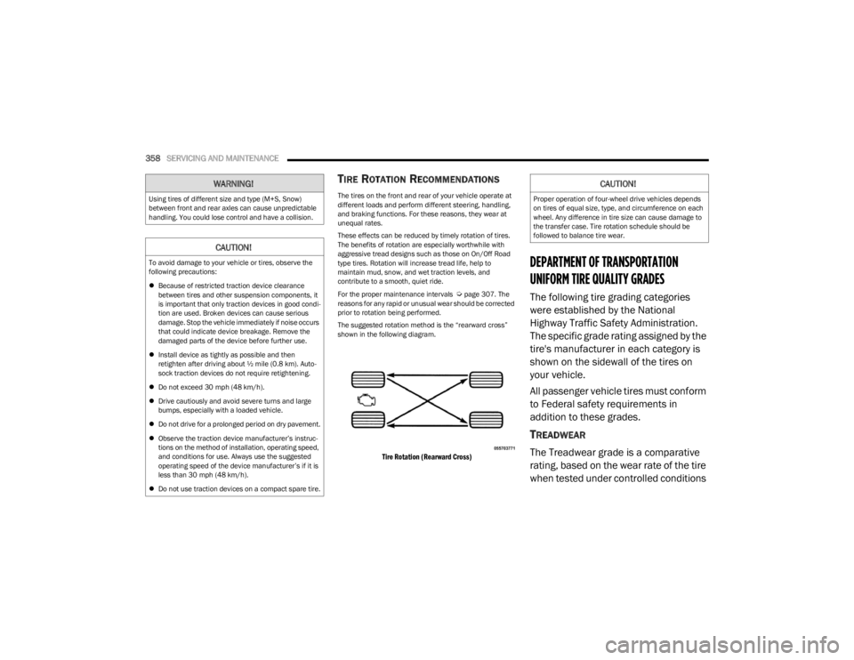
The suggested rotation method is the “rearward cross”
shown in the following diagram.
Tire Rotation (Rearward Cross)
DEPARTMENT OF TRANSPORTATION
UNIFORM TIRE QUALITY GRADES
The following tire grading categories
were established by the National
Highway Traffic Safety Administration.
The specific grade rating assigned by the
tire's manufacturer in each category is
shown on the sidewall of the tires on
your vehicle.
All passenger vehicle tires must conform
to Federal safety requirements in
addition to these grades.
TREADWEAR
The Treadwear grade is a comparative
rating, based on the wear rate of the tire
when tested under controlled conditions
WARNING!
Using tires of different size and type (M+S, Snow)
between front and rear axles can cause unpredictable
handling. You could lose control and have a collision.
CAUTION!
To avoid damage to your vehicle or tires, observe the
following precautions:
Because of restricted traction device clearance
between tires and other suspension components, it
is important that only traction devices in good condi -
tion are used. Broken devices can cause serious
damage. Stop the vehicle immediately if noise occurs
that could indicate device breakage. Remove the
damaged parts of the device before further use.
Install device as tightly as possible and then
retighten after driving about ½ mile (0.8 km). Auto -
sock traction devices do not require retightening.
Do not exceed 30 mph (48 km/h).
Drive cautiously and avoid severe turns and large
bumps, especially with a loaded vehicle.
Do not drive for a prolonged period on dry pavement.
Observe the traction device manufacturer’s instruc -
tions on the method of installation, operating speed,
and conditions for use. Always use the suggested
operating speed of the device manufacturer’s if it is
less than 30 mph (48 km/h).
Do not use traction devices on a compact spare tire.
CAUTION!
Proper operation of four-wheel drive vehicles depends
on tires of equal size, type, and circumference on each
wheel. Any difference in tire size can cause damage to
the transfer case. Tire rotation schedule should be
followed to balance tire wear.
23_JL_OM_EN_USC_t.book Page 358
Page 361 of 396
SERVICING AND MAINTENANCE359
on a specified government test course.
For example, a tire graded 150 would
wear one and one-half times as well on
the government course as a tire graded
100. The relative performance of tires
depends upon the actual conditions of
their use, however, and may depart
significantly from the norm due to
variations in driving habits, service
practices, and differences in road
characteristics and climate.
TRACTION GRADES
The Traction grades, from highest to
lowest, are AA, A, B, and C. These grades
represent the tire's ability to stop on wet
pavement, as measured under
controlled conditions on specified
government test surfaces of asphalt and
concrete. A tire marked C may have poor
traction performance.
TEMPERATURE GRADES
The Temperature grades are A (the
highest), B, and C, representing the tire's
resistance to the generation of heat and
its ability to dissipate heat, when tested
under controlled conditions on a
specified indoor laboratory test wheel.
Sustained high temperature can cause
the material of the tire to degenerate
and reduce tire life, and excessive
temperature can lead to sudden tire
failure. The grade C corresponds to a
level of performance, which all
passenger vehicle tires must meet
under the Federal Motor Vehicle Safety
Standard No. 109. Grades B and A
represent higher levels of performance on the laboratory test wheel, than the
minimum required by law.
STORING THE VEHICLE
WARNING!
The traction grade assigned to this tire is based on
straight-ahead braking traction tests, and does not
include acceleration, cornering, hydroplaning, or peak
traction characteristics.
WARNING!
The temperature grade for this tire is established for a
tire that is properly inflated and not overloaded.
Excessive speed, underinflation, or excessive loading,
either separately or in combination, can cause heat
buildup and possible tire failure.
WARNING!
Take care to avoid the radiator cooling fan whenever
the hood is raised. It can start anytime the ignition
switch is ON. You can be injured by moving fan
blades.
Remove any metal jewelry such as rings, watch
bands and bracelets that could make an inadvertent
electrical contact. You could be seriously injured.
Vehicles with the Stop/Start system will be equipped
with two batteries. Both the main and the supple -
mental batteries must be disconnected to
completely de-energize the 12 Volt electrical system.
Serious injury or death could result if you do not
disconnect both batteries. To learn how to properly
disconnect, see an authorized dealer.
8
23_JL_OM_EN_USC_t.book Page 359
Page 388 of 396

386
K
Key Fob Arm The System .........................................................20
Disarm The System....................................................20
Programming Additional Key Fobs ...........................15
Key Fob Battery Service (Remote Keyless Entry) .........14
Key Fob Programming (Remote Keyless Entry) ............ 15
Keyless Enter 'n Go™ ...................................................... 21 Passive Entry .............................................................. 21
Keys .................................................................................13 Replacement .............................................................. 15
LLane Change Assist ........................................................52
Lap/Shoulder Belts ...................................................... 262
Latches ......................................................................... 290 Hood ............................................................... 100
, 118
Leaks, Fluid .................................................................. 290
Life Of Tires .................................................................. 354
Light Bulbs ........................................................... 290
, 342
Lights ............................................................................ 290 Air Bag ...................................................117
, 267, 289
Automatic Headlights ................................................51
Brake Assist Warning ............................................. 247
Brake Warning ........................................................ 117 Bulb Replacement ......................................... 342
, 343
Center Mounted Stop ............................................. 345
Cruise.............................................................. 123
, 124
Daytime Running ....................................................... 51
Dimmer Switch, Headlight.........................................51
Electric Power Steering .......................................... 118
Electronic Stability Program (ESP) Indicator .. 118
, 119
Exterior ............................................................. 50, 290
Fog ........................................................................... 344 Fuel Filler Cap .......................................................... 120
Hazard Warning Flasher ......................................... 291
Headlights ................................................................ 343
High Beam ................................................................. 51
High Beam/Low Beam Select .................................. 51
Hill Descent Control Indicator................................. 248
Interior........................................................................ 52
Lights On Reminder................................................... 51
Low Fuel ...................................................................120 Low Washer Fluid ....................................................120Malfunction Indicator (Check Engine).................... 120
Oil Temperature ....................................................... 118
Park .......................................................................... 123Passing....................................................................... 51
Rear Servicing.......................................................... 344
Rear Tail Lamps....................................................... 344
Seat Belt Reminder ................................................. 118
Security Alarm.......................................................... 119
Service ........................................................... 342
, 343
Side Marker ............................................................. 344
Tire Pressure Monitoring (TPMS)............................ 257
Traction Control ....................................................... 247
Transmission Temperature..................................... 119
Turn Signal ............................................................... 290
Turn Signals ................................................... 123
, 344
Warning Instrument Cluster Descriptions.... 118, 123
Load Floor, Cargo.......................................................... 102
Load Shed Battery Saver Mode ...................................114
Load Shed Battery Saver On ........................................ 114
Load Shed Electrical Load Reduction ......................... 114
Load Shed Intelligent Battery Sensor..........................114
Loading Vehicle............................................................. 169 Tires.......................................................................... 349
Locking Axle ...........................................................................144 Locks
Automatic Door ......................................................... 23
Child Protection ......................................................... 23
Power Door ................................................................ 21
Low Tire Pressure System............................................ 257
Lowering The Soft Top Into Sunrider® Position
S
.... 67
Lubrication, Body.......................................................... 326
Lug Nuts/Bolts ............................................................. 368
Luggage Carrier ............................................................ 102
MMaintenance................................................................... 91
Maintenance Free Battery ........................................... 317
Maintenance Schedule .......................................306
, 310
Malfunction Indicator Light (Check Engine) ......120, 125
Manage My Account..................................................... 237
Manual Park Release ........................................................... 301
Service ..................................................................... 380
Manual Transmission..........................................134
, 332
Fluid Level Check .................................................... 332
Lubricant Selection ........................................332
, 376
Shift Speeds ............................................................ 135
Media Mode .................................................................. 210
Methanol ....................................................................... 370
Mirrors ............................................................................. 45 Automatic Dimming .................................................. 45
Electric Powered ....................................................... 46
Electric Remote ......................................................... 46
Heated ....................................................................... 46
Outside....................................................................... 46
Rearview .................................................................... 45
Vanity ......................................................................... 46
Mobile App .................................................................... 227
23_JL_OM_EN_USC_t.book Page 386
Page 392 of 396

390
Towing .........................................................170, 172, 303
Disabled Vehicle ..................................................... 303
Recreational ............................................................ 176
Weight...................................................................... 172
Towing Behind A Motorhome ...................................... 176
Trac-Lok Rear Axle ................................................................. 144
Traction Control............................................................ 251
Trailer Sway Control (TSC) ........................................... 251
Trailer Towing ............................................................... 170 Hitches .................................................................... 172
Minimum Requirements ........................................ 173
Trailer And Tongue Weight ............................ 172
, 173
Wiring....................................................................... 174
Trailer Towing Guide .................................................... 172
Trailer Weight ............................................................... 172
Transfer Case ............................................................... 332 Fluid ......................................................................... 376
Four-Wheel-Drive-Operation .......................... 141
, 142
Maintenance ........................................................... 332
Transmission ................................................................ 138 Automatic ....................................................... 138
, 333
Fluid ......................................................................... 376
Maintenance ........................................................... 333
Manual .................................................................... 134
Shifting .................................................................... 137
Transporting Pets ......................................................... 288
Tread Wear Indicators ................................................. 354
Turn Signals......................................................... 123
, 344
UUCI Connector .................................................................61 Uconnect Phone Call Features ............................................... 217 Things You Should Know About Your Uconnect
Phone .................................................................. 220
Uconnect Settings ..................................................... 18
Uconnect Phone ................................................. 214
, 215
Answer Or Ignore An Incoming Call — Call Currently In Progress ..................................219
Answer Or Ignore An Incoming Call — No Call Currently In Progress............................. 219
Bluetooth Communication Link .............................. 222
Call Continuation ..................................................... 220 Call Controls............................................................. 218
Call Termination ...................................................... 220
Cancel Command ....................................................214Connecting To A Particular Mobile Phone Or Audio
Device After Pairing............................................216
Help Command........................................................ 214
Join Calls .................................................................. 220
Making A Phone Or Audio Device A Favorite .........216 Making A Second Call While Current Call Is In Progress .............................................................. 220
Managing Your Favorites ........................................ 217
Natural Speech........................................................ 214
Operation ................................................................. 213
Overview...................................................................212 Pair (Link) Uconnect Phone To A Mobile Phone .... 214
Pair A Bluetooth Streaming Audio Device.............. 215
Phonebook Download ............................................. 217Place/Retrieve A Call From Hold ............................ 219
Power-Up .................................................................. 222
Recent Calls ............................................................. 218
Redial ....................................................................... 220
To Remove A Favorite ............................................. 217 Toggling Between Calls........................................... 220
Touch-Tone Number Entry ...................................... 218
Transfer Call To And From Mobile Phone .............. 220
Voice Command ...................................................... 220
Uconnect Settings ........................................................ 184 Customer Programmable Features ......... 18
, 21, 184
Passive Entry Programming ..................................... 21
Uconnect System.......................................................... 197
Uniform Tire Quality Grades ........................................ 358
Universal Consumer Interface (UCI) Connector ........... 61
Universal Garage Door Opener (HomeLink®) —
If Equipped
S
.............................................................. 47
Untwisting Procedure, Seat Belt.................................. 264
USB.................................................................................. 61
USB Port .......................................................................... 61
VVanity Mirrors ................................................................. 46
Vehicle Finder ......................................................233, 238
Vehicle Health Alert ...................................................... 235
Vehicle Health Report .................................................. 234
Vehicle Identification Number (VIN) ............................ 368
Vehicle Loading ...................................................169
, 349
Vehicle Maintenance ................................................... 318
Vehicle Modifications/Alterations ....................................8
Vehicle Notifications .................................................... 235
Vehicle Settings ............................................................ 184
Vehicle Storage............................................................. 359
Voice Command ........................................... 44
, 223, 225
Climate....................................................................... 59
Voice Recognition ........................................................... 44
Voice Recognition System (VR) ..................................... 44
23_JL_OM_EN_USC_t.book Page 390