torque JEEP WRANGLER 2023 Owner's Manual
[x] Cancel search | Manufacturer: JEEP, Model Year: 2023, Model line: WRANGLER, Model: JEEP WRANGLER 2023Pages: 396, PDF Size: 25.15 MB
Page 147 of 396
STARTING AND OPERATING145
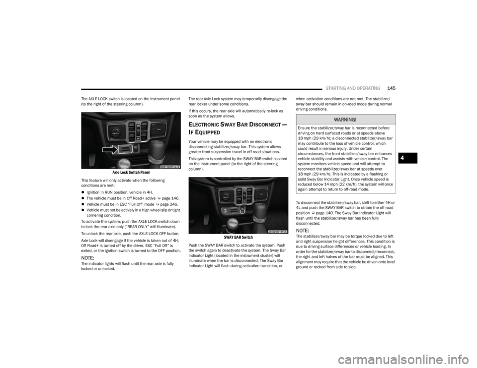
The AXLE LOCK switch is located on the instrument panel
(to the right of the steering column).
Axle Lock Switch Panel
This feature will only activate when the following
conditions are met:
Ignition in RUN position, vehicle in 4H.
The vehicle must be in Off Road+ active
Úpage 146.
Vehicle must be in ESC “Full Off” mode Úpage 246.
Vehicle must not be actively in a high wheel slip or tight
cornering condition.
To activate the system, push the AXLE LOCK switch down
to lock the rear axle only (“REAR ONLY” will illuminate).
To unlock the rear axle, push the AXLE LOCK OFF button.
Axle Lock will disengage if the vehicle is taken out of 4H,
Off Road+ is turned off by the driver, ESC “Full Off” is
exited, or the ignition switch is turned to the OFF position.
NOTE:The indicator lights will flash until the rear axle is fully
locked or unlocked. The rear Axle Lock system may temporarily disengage the
rear locker under some conditions.
If this occurs, the rear axle will automatically re-lock as
soon as the system allows.
ELECTRONIC SWAY BAR DISCONNECT —
I
F EQUIPPED
Your vehicle may be equipped with an electronic
disconnecting stabilizer/sway bar. This system allows
greater front suspension travel in off-road situations.
This system is controlled by the SWAY BAR switch located
on the instrument panel (to the right of the steering
column).
SWAY BAR Switch
Push the SWAY BAR switch to activate the system. Push
the switch again to deactivate the system. The Sway Bar
Indicator Light (located in the instrument cluster) will
illuminate when the bar is disconnected. The Sway Bar
Indicator Light will flash during activation transition, or when activation conditions are not met. The stabilizer/
sway bar should remain in on-road mode during normal
driving conditions.
To disconnect the stabilizer/sway bar, shift to either 4H or
4L and push the SWAY BAR switch to obtain the off-road
position
Úpage 140. The Sway Bar Indicator Light will
flash until the stabilizer/sway bar has been fully
disconnected.
NOTE:The stabilizer/sway bar may be torque locked due to left
and right suspension height differences. This condition is
due to driving surface differences or vehicle loading. In
order for the stabilizer/sway bar to disconnect/reconnect,
the right and left halves of the bar must be aligned. This
alignment may require that the vehicle be driven onto level
ground or rocked from side to side.
WARNING!
Ensure the stabilizer/sway bar is reconnected before
driving on hard surfaced roads or at speeds above
18 mph (29 km/h); a disconnected stabilizer/sway bar may contribute to the loss of vehicle control, which
could result in serious injury. Under certain
circumstances, the front stabilizer/sway bar enhances
vehicle stability and assists with vehicle control. The
system monitors vehicle speed and will attempt to
reconnect the stabilizer/sway bar at speeds over
18 mph (29 km/h). This is indicated by a flashing or solid Sway Bar Indicator Light. Once vehicle speed is
reduced below 14 mph (22 km/h), the system will once
again attempt to return to off-road mode.
4
23_JL_OM_EN_USC_t.book Page 145
Page 149 of 396
STARTING AND OPERATING147
If the “SERVICE POWER STEERING” message and a
flashing icon are displayed on the instrument cluster
screen, it indicates that the vehicle needs to be taken to
an authorized dealer for service. It is likely the vehicle has
lost power steering assistance
Úpage 108.
If the “POWER STEERING HOT” message and an icon are
displayed on the instrument cluster screen, it indicates
that extreme steering maneuvers may have occurred,
which caused an over temperature condition in the power
steering system. You will lose power steering assistance
momentarily until the over temperature condition no
longer exists. Once driving conditions are safe, pull over
and let vehicle idle for a few moments until the light turns
off
Úpage 108.
NOTE:
Even if power steering assistance is no longer opera -
tional, it is still possible to steer the vehicle. Under
these conditions there will be a substantial increase in
steering effort, especially at very low vehicle speeds
and during parking maneuvers.
If the condition persists, see an authorized dealer for
service.
STOP/START SYSTEM — AUTOMATIC
TRANSMISSION (IF EQUIPPED)
The Engine Stop/Start (ESS) function is designed to
reduce fuel consumption. The system will stop the engine
automatically during a vehicle stop if the required
conditions are met. Releasing the brake pedal or pressing
the accelerator pedal will automatically restart the engine. ESS vehicles have been upgraded with a heavy-duty
starter, enhanced battery, and other upgraded engine
parts, to handle the additional engine starts. Vehicles
equipped with eTorque contain a heavy-duty motor
generator and an additional hybrid electric battery to store
energy from vehicle deceleration for use on engine startup
after a stop as well as providing launch torque assist.
NOTE:It is recommended that Stop/Start system be disabled
during off-road use.
Secondary Battery
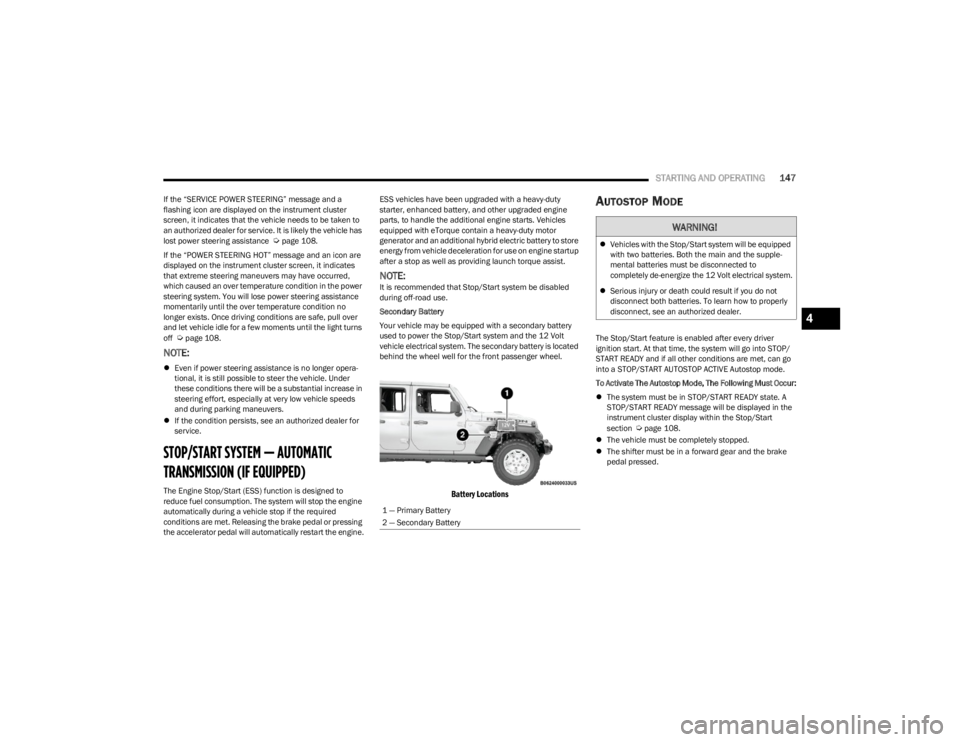
Your vehicle may be equipped with a secondary battery
used to power the Stop/Start system and the 12 Volt
vehicle electrical system. The secondary battery is located
behind the wheel well for the front passenger wheel.
Battery Locations
AUTOSTOP MODE
The Stop/Start feature is enabled after every driver
ignition start. At that time, the system will go into STOP/
START READY and if all other conditions are met, can go
into a STOP/START AUTOSTOP ACTIVE Autostop mode.
To Activate The Autostop Mode, The Following Must Occur:
The system must be in STOP/START READY state. A
STOP/START READY message will be displayed in the
instrument cluster display within the Stop/Start
section
Úpage 108.
The vehicle must be completely stopped.
The shifter must be in a forward gear and the brake
pedal pressed.
1 — Primary Battery
2 — Secondary Battery
WARNING!
Vehicles with the Stop/Start system will be equipped
with two batteries. Both the main and the supple -
mental batteries must be disconnected to
completely de-energize the 12 Volt electrical system.
Serious injury or death could result if you do not
disconnect both batteries. To learn how to properly
disconnect, see an authorized dealer.
4
23_JL_OM_EN_USC_t.book Page 147
Page 151 of 396
STARTING AND OPERATING149
TO MANUALLY TURN ON THE STOP/
S
TART SYSTEM
Push the Stop/Start OFF switch (located on the switch
bank). The light on the switch will turn off.
SYSTEM MALFUNCTION
If there is a malfunction in the Stop/Start system, the
system will not shut down the engine. A “SERVICE STOP/
START SYSTEM” message and a yellow Stop/Start telltale
will appear in the Instrument Cluster Display
Úpage 108.
If the “SERVICE STOP/START SYSTEM” message appears
in the instrument cluster display, have the system
checked by an authorized dealer.
If a malfunction occurs during an autostop, the vehicle
may not auto start and will need a key start.
STOP/START SYSTEM — MANUAL
TRANSMISSION (IF EQUIPPED)
The Engine Stop/Start (ESS) function is designed to
reduce fuel consumption. The system will stop the engine
automatically during a vehicle stop if the required
conditions are met. Pressing the clutch pedal will
automatically restart the vehicle.
ESS vehicles have been upgraded with a heavy-duty
starter, enhanced battery, and other upgraded engine
parts, to handle the additional engine starts. Vehicles
equipped with eTorque contain a heavy duty motor generator and an additional hybrid electric battery to store
energy from vehicle deceleration for use on engine startup
after a stop as well as providing launch torque assist.
NOTE:It is recommended that Stop/Start be disabled during
off-road use.
Secondary Battery
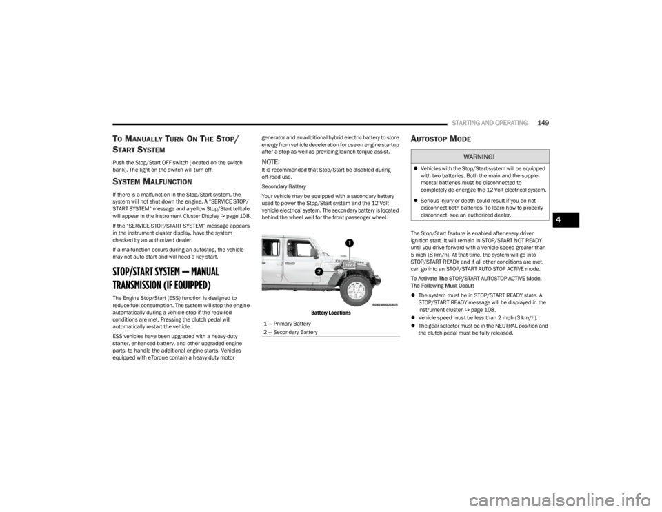
Your vehicle may be equipped with a secondary battery
used to power the Stop/Start system and the 12 Volt
vehicle electrical system. The secondary battery is located
behind the wheel well for the front passenger wheel.
Battery Locations
AUTOSTOP MODE
The Stop/Start feature is enabled after every driver
ignition start. It will remain in STOP/START NOT READY
until you drive forward with a vehicle speed greater than
5 mph (8 km/h). At that time, the system will go into
STOP/START READY and if all other conditions are met,
can go into an STOP/START AUTO STOP ACTIVE mode.
To Activate The STOP/START AUTOSTOP ACTIVE Mode,
The Following Must Occur:
The system must be in STOP/START READY state. A
STOP/START READY message will be displayed in the
instrument cluster
Úpage 108.
Vehicle speed must be less than 2 mph (3 km/h).
The gear selector must be in the NEUTRAL position and
the clutch pedal must be fully released.
1 — Primary Battery
2 — Secondary Battery
WARNING!
Vehicles with the Stop/Start system will be equipped
with two batteries. Both the main and the supple -
mental batteries must be disconnected to
completely de-energize the 12 Volt electrical system.
Serious injury or death could result if you do not
disconnect both batteries. To learn how to properly
disconnect, see an authorized dealer.
4
23_JL_OM_EN_USC_t.book Page 149
Page 170 of 396
168STARTING AND OPERATING
System Overview
This vehicle is equipped with a Diesel Exhaust Fluid (DEF)
injection system and a Selective Catalytic Reduction (SCR)
catalyst to meet the emission requirements.
The DEF injection system consists of the following
components:
DEF tank
DEF pump
DEF injector
Electronically-heated DEF Lines
NOx sensors
Temperature sensors
SCR catalyst
The DEF injection system and SCR catalyst enable the
achievement of diesel emission requirements; while
maintaining outstanding fuel economy, drivability, torque
and power ratings.
For system messages and warnings see
Úpage 108.
NOTE:
Your vehicle is equipped with a DEF injection system.
You may occasionally hear an audible clicking noise
from under the vehicle at a stop. This is normal opera -
tion.
The DEF pump will run for a period of time after engine
shutdown to purge the DEF system. This is normal
operation and may be audible from the rear of the
vehicle.
Diesel Exhaust Fluid Storage
Diesel Exhaust Fluid (DEF) is considered a very stable
product with a long shelf life. If DEF is kept in
temperatures between 10° and 90°F (-12° and 32°C), it
will last a minimum of one year.
DEF is subject to freezing at the lowest temperatures. For
example, DEF may freeze at temperatures at or below
12°F (-11°C). The system has been designed to operate
in this environment.
NOTE:When working with DEF, it is important to know that:
Any containers or parts that come into contact with DEF
must be DEF compatible (plastic or stainless steel).
Copper, brass, aluminum, iron or non-stainless steel
should be avoided as they are subject to corrosion by
DEF.
If DEF is spilled, it should be wiped up completely.
Adding Diesel Exhaust Fluid
The DEF gauge (located on the instrument cluster display)
will display the level of DEF remaining in the tank
Úpage 108.
NOTE:Driving conditions (altitude, vehicle speed, load, etc.) will
affect the amount of DEF that is used in your vehicle.
DEF FILL PROCEDURE
NOTE:
For the correct DEF fluid type see Úpage 374.
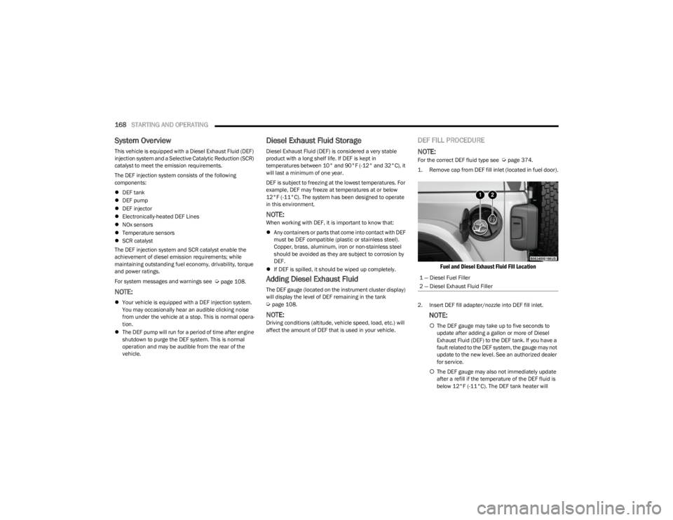
1. Remove cap from DEF fill inlet (located in fuel door).
Fuel and Diesel Exhaust Fluid Fill Location
2. Insert DEF fill adapter/nozzle into DEF fill inlet.
NOTE:
The DEF gauge may take up to five seconds to
update after adding a gallon or more of Diesel
Exhaust Fluid (DEF) to the DEF tank. If you have a
fault related to the DEF system, the gauge may not
update to the new level. See an authorized dealer
for service.
The DEF gauge may also not immediately update
after a refill if the temperature of the DEF fluid is
below 12°F (-11°C). The DEF tank heater will
1 — Diesel Fuel Filler
2 — Diesel Exhaust Fluid Filler
23_JL_OM_EN_USC_t.book Page 168
Page 185 of 396
STARTING AND OPERATING183
CROSSING DITCHES, STREAMS, SHALLOW
RIVERS OR OTHER FLOWING WATER
Flowing water can be extremely dangerous. Never attempt
to cross a fast running stream or river even in shallow
water. Fast moving water can easily push your vehicle
downstream, sweeping it out of control. Even in very
shallow water, a high current can still wash the dirt out
from around your tires putting you and your vehicle in
jeopardy. There is still a high risk of personal injury and
vehicle damage with slower water currents in depths
greater than the vehicle's running ground clearance. You
should never attempt to cross flowing water which is
deeper than the vehicle's running ground clearance. Even
the slowest current can push the heaviest vehicle
downstream and out of control if the water is deep enough
to push on the large surface area of the vehicle's body.
Before you proceed, determine the speed of the current,
the water's depth, approach angle, bottom condition and
if there are any obstacles. Then cross at an angle heading
slightly upstream using the low and slow technique.
After Driving Off-Road
Off-road operation puts more stress on your vehicle than
does most on-road driving. After going off-road, it is always
a good idea to check for damage. That way you can get any
problems taken care of right away and have your vehicle
ready when you need it.
Completely inspect the underbody of your vehicle.
Check tires, body structure, steering, suspension, and
exhaust system for damage.
Inspect the radiator for mud and debris and clean as
required.
Check threaded fasteners for looseness, particularly
on the chassis, drivetrain components, steering, and
suspension. Retighten them, if required, and torque to
the values specified in the Service Manual.
Check for accumulations of plants or brush. These
things could be a fire hazard. They might hide damage
to fuel lines, brake hoses, axle pinion seals, and
propeller shafts.
After extended operation in mud, sand, water, or
similar dirty conditions, have the radiator, fan, brake
rotors, wheels, brake linings, and axle yokes inspected
and cleaned as soon as possible.
NOTE:Inspect the clutch vent holes in the manual transmission
bell housing for mud and debris and clean as required.
If you experience unusual vibration after driving in
mud, slush or similar conditions, check the wheels for
impacted material. Impacted material can cause a
wheel imbalance and freeing the wheels of it will
correct the situation.
WARNING!
Never drive through fast moving deep water. It can push
your vehicle downstream, sweeping it out of control.
This could put you and your passengers at risk of injury
or drowning.
WARNING!
Abrasive material in any part of the brakes may cause
excessive wear or unpredictable braking. You might not
have full braking power when you need it to prevent a
collision. If you have been operating your vehicle in dirty
conditions, get your brakes checked and cleaned as
necessary.
4
23_JL_OM_EN_USC_t.book Page 183
Page 189 of 396
MULTIMEDIA187
Units
Voice
When the Units button is pressed on the touchscreen, the system displays the different measurement options. The selected unit of measurement will display in the instrument cluster
display and Navigation system (if equipped). The available settings are:
NOTE:Depending on the vehicle’s options, feature settings may vary.
Setting Name Description
USThis setting will change the unit of measurement on the display to US.
Metric This setting will change the unit of measurement on the display to Metric.
Custom This setting will allow you to change the units. The available options are “Speed” (MPH or
km/h), “Distance” (mi or km), “Fuel Consumption” (MPG [US], MPG [UK], L/100 km, or
km/L), “Pressure” (psi, kPa, or bar), “Temperature” (°C or °F), “Power” (HP [US], Gal HP
[UK], or kW), and “Torque” (lb-ft or Nm) units of measurement independently.
When the Voice button is pressed on the touchscreen, the system displays the options related to the vehicle’s Voice Recognition feature.
NOTE:Depending on the vehicle’s options, feature settings may vary.
Setting Name
Description
Voice Response LengthThis setting will change the response length for the Voice Recognition system. The “Brief”
setting provides a shortened audio description from the system. The “Detailed” setting
provides the full audio description from the system.
Show Command List This setting will allow you to turn the Command List on or off. The “Always” setting will
always show the Command List. The “With Help” setting will show the Command List and
provide a brief description of what the command does. The “Never” setting will turn the
Command List off.
5
23_JL_OM_EN_USC_t.book Page 187
Page 247 of 396
SAFETY245
To enable or disable RSRA, see Úpage 184.
ELECTRONIC BRAKE CONTROL (EBC)
S
YSTEM
If applicable, refer to the “Hybrid Supplement” for
additional information.
Your vehicle is equipped with an advanced Electronic
Brake Control (EBC) system. This system includes
Anti-Lock Brake System (ABS), Brake Assist System (BAS),
Electronic Brake Force Distribution (EBD), Electronic Roll
Mitigation (ERM), Electronic Stability Control (ESC), Hill
Start Assist (HSA), and Traction Control System (TCS). These systems work together to enhance both vehicle
stability and control in various driving conditions.
Your vehicle may also be equipped with Hill Descent
Control (HDC), Rain Brake Support (RBS), Ready Alert
Braking (RAB), and Trailer Sway Control (TSC).
Brake System Warning Light
The red Brake System Warning Light will turn on when the
ignition is placed in the ON/RUN mode and may stay on for
as long as four seconds.
If the Brake System Warning Light remains on or comes on
while driving, it indicates that the brake system is not
functioning properly and that immediate service is
required. If the Brake System Warning Light does not
come on when the ignition is placed in the ON/RUN mode,
have the light repaired as soon as possible.
Brake Assist System (BAS)
The BAS is designed to optimize the vehicle’s braking
capability during emergency braking maneuvers. The
system detects an emergency braking situation by sensing
the rate and amount of brake application and then applies
optimum pressure to the brakes. This can help reduce
braking distances. The BAS complements the Anti-Lock
Brake System (ABS). Applying the brakes very quickly
results in the best BAS assistance. To receive the benefit
of the system, you must apply continuous braking
pressure during the stopping sequence (do not “pump”
the brakes). Do not reduce brake pedal pressure unless
braking is no longer desired. Once the brake pedal is
released, the BAS is deactivated.
Electronic Brake Force Distribution (EBD)
EBD manages the distribution of the braking torque
between the front and rear axles by limiting braking
pressure to the rear axle. This is done to prevent overslip
of the rear wheels to avoid vehicle instability, and to
prevent the rear axle from entering ABS before the front
axle.
Electronic Roll Mitigation (ERM)
ERM anticipates the potential for wheel lift by monitoring
the driver’s steering wheel input and the speed of the
vehicle. When ERM determines that the rate of change of
the steering wheel angle and vehicle’s speed are
sufficient to potentially cause wheel lift, it then applies the
appropriate brake and may also reduce engine power to
lessen the chance that wheel lift will occur. ERM can only
reduce the chance of wheel lift occurring during severe or
evasive driving maneuvers; it cannot prevent wheel lift
due to other factors, such as road conditions, leaving the
roadway, or striking objects or other vehicles.
WARNING!
Before exiting a vehicle, always come to a complete
stop, then shift the automatic transmission into
PARK and apply the parking brake.
Always make sure the keyless ignition node is in the
OFF position, key fob is removed from the vehicle
and vehicle is locked.
Never leave children alone in a vehicle, or with
access to an unlocked vehicle. Leaving children in a
vehicle unattended is dangerous for a number of
reasons. A child or others could be seriously or fatally
injured. Children should be warned not to touch the
parking brake, brake pedal or the gear selector.
Do not leave children or animals inside parked vehi -
cles in hot weather. Interior heat buildup may cause
serious injury or death.
WARNING!
The Brake Assist System (BAS) cannot prevent the natu -
ral laws of physics from acting on the vehicle, nor can it
increase the traction afforded by prevailing road condi -
tions. BAS cannot prevent collisions, including those
resulting from excessive speed in turns, driving on very
slippery surfaces, or hydroplaning. The capabilities of a
BAS-equipped vehicle must never be exploited in a
reckless or dangerous manner, which could jeopardize
the user's safety or the safety of others.
6
23_JL_OM_EN_USC_t.book Page 245
Page 249 of 396
SAFETY247
To enter the “Partial Off” mode, momentarily push the ESC
OFF button and the ESC OFF Indicator Light will illuminate.
To turn the ESC on again, momentarily push the ESC OFF
button and the ESC OFF Indicator Light will turn off.
NOTE:For vehicles with multiple partial ESC modes, the push and
release of the button will toggle the ESC modes. Multiple
attempts may be required to return to “ESC On”.
Full Off — If Equipped
The “Full Off” mode is intended for off-highway or off-road
use only and should not be used on any public roadways.
In this mode, TCS and ESC features are turned off. To
enter the “Full Off” mode, push and hold the ESC OFF
button for five seconds while the vehicle is stopped with
the engine running. After five seconds, a chime will sound,
the ESC OFF Indicator Light will illuminate, and the “ESC
Off” message will display in the instrument cluster. To turn
ESC on again, momentarily push the ESC OFF button.
NOTE:System may switch from ESC “Full Off” to “Partial Off”
mode when vehicle exceeds a predetermined speed.
When the vehicle speed slows below the predetermined
speed the system will return to ESC “Full Off”.
If equipped with Off Road+ and if Off Road+ is active when
"Full Off" mode is enabled by the driver, ESC will not switch
to "Partial Off" mode at any speed and will remain in "Full
Off" mode until Off Road+ is exited or ESC is re-enabled by
the driver.ESC Activation/Malfunction Indicator Light
And ESC OFF Indicator Light
The ESC Activation/Malfunction Indicator Light
in the instrument cluster will come on when the
ignition is turned to the “ESC On” mode. It
should go out with the engine running. If the
ESC Activation/Malfunction Indicator Light comes on
continuously with the engine running, a malfunction has
been detected in the ESC system. If this light remains on
after several ignition cycles, and the vehicle has been
driven several miles (km) at speeds greater than 30 mph
(48 km/h), see an authorized dealer as soon as possible
to have the problem diagnosed and corrected.
The ESC Activation/Malfunction Indicator Light starts to
flash as soon as the tires lose traction and the ESC system
becomes active. The ESC Activation/Malfunction Indicator
Light also flashes when TCS is active. If the ESC
Activation/Malfunction Indicator Light begins to flash
during acceleration, ease up on the accelerator and apply
as little throttle as possible. Be sure to adapt your speed
and driving to the prevailing road conditions.
The ESC OFF Indicator Light indicates the
customer has elected to have the Electronic
Stability Control (ESC) in a reduced mode.
NOTE:
The ESC Activation/Malfunction Indicator Light and the
ESC OFF Indicator Light come on momentarily each
time the ignition is placed in the ON position.
WARNING!
When in “Partial Off” mode, the TCS functionality of
ESC, except for the limited slip feature described in
the TCS section, has been disabled and the ESC OFF
Indicator Light will be illuminated. When in “Partial
Off” mode, the engine power reduction feature of
TCS is disabled, and the enhanced vehicle stability
offered by the ESC system is reduced.
Trailer Sway Control (TSC) is disabled when the ESC
system is in the “Partial Off” mode.WARNING!
In the ESC “Full Off” mode, the engine torque reduc -
tion and stability features are disabled. Therefore,
enhanced vehicle stability offered by the ESC system
is unavailable. In an emergency evasive maneuver,
the ESC system will not engage to assist in main -
taining stability. ESC “Full Off” mode is intended for
off-highway or off-road use only.
The Electronic Stability Control (ESC) cannot prevent
the natural laws of physics from acting on the
vehicle, nor can it increase the traction afforded by
prevailing road conditions. ESC cannot prevent all
accidents, including those resulting from excessive
speed in turns, driving on very slippery surfaces, or
hydroplaning. ESC also cannot prevent collisions.
6
23_JL_OM_EN_USC_t.book Page 247
Page 252 of 396
250SAFETY
Ready Alert Braking (RAB)
RAB may reduce the time required to reach full braking
during emergency braking situations. It anticipates when
an emergency braking situation may occur by monitoring
how fast the throttle is released by the driver. The
Electronic Brake Controller (EBC) will prepare the brake
system for a panic stop.
Selec-Speed Control (SSC) — If Equipped
SSC is intended for off-road driving in 4WD Low
only. SSC maintains vehicle speed by actively
controlling engine torque and brakes.
SSC has three states:
1. Off (feature is not enabled and will not activate)
2. Enabled (feature is enabled and ready but activation conditions are not met, or driver is actively overriding
with brake or throttle application)
3. Active (feature is enabled and actively controlling vehicle speed)
Enabling SSC
SSC is enabled by pushing the SSC switch, but the
following conditions must also be met to enable SSC:
The driveline is in 4WD Low.
The vehicle speed is below 5 mph (8 km/h).
The parking brake is released.
The driver door is closed (If doors are attached, the
door must be closed. If doors are detached, the driver
seat belt must be buckled).
The driver is not applying throttle. Activating SSC
Once SSC is enabled it will activate automatically once the
following conditions are met:
The driver releases the throttle.
The driver releases the brake.
The driver seat belt is buckled.
The transmission is in any selection other than PARK.
Your vehicle speed is below 20 mph (32 km/h).
The driver door is closed. (If doors are attached, the
door must be closed. If doors are detached, the driver
seat belt must be buckled).
The set speed for SSC is selectable by the driver, and can
be adjusted by using the gear shift +/-. Additionally, the
SSC set speed may be reduced when climbing a grade and
the level of set speed reduction depends on the
magnitude of grade. The following summarizes the SSC
set speeds:
SSC Target Set Speeds
1st = 0.6 mph (1 km/h)
2nd = 1.2 mph (2 km/h)
3rd = 1.8 mph (3 km/h)
4th = 2.5 mph (4 km/h)
5th = 3.1 mph (5 km/h)
6th = 3.7 mph (6 km/h)
7th = 4.3 mph (7 km/h)
8th = 5 mph (8 km/h)
9th = 5.6 mph (9 km/h) — if equipped
REVERSE = 0.6 mph (1 km/h)
NEUTRAL = 1.2 mph (2 km/h)
PARK = SSC remains enabled but not active SSC Target Set Speeds — If Equipped With Off Road+
1st = 0.6 mph (1 km/h)
2nd = 0.9 mph (1.5 km/h)
3rd = 1.2 mph (2 km/h)
4th = 1.5 mph (2.5 km/h)
5th = 1.8 mph (3 km/h)
6th = 2.5 mph (4 km/h)
7th = 3.7 mph (6 km/h)
8th = 5 mph (8 km/h)
REVERSE = 0.6 mph (1 km/h)
NEUTRAL = 1.2 mph (2 km/h)
PARK = SSC remains enabled but not active
NOTE:
During SSC, the +/- gear selector input is used for SSC
target speed selection but will not affect the gear
chosen by the transmission. While actively controlling
SSC, the transmission will shift appropriately for the
driver-selected set speed and corresponding driving
conditions.
SSC operation is influenced by Off Road+ drive mode if
active. The differences may be notable to the driver as
a varying level of aggressiveness.
Driver Override
The driver may override SSC activation with throttle or
brake application at any time.
23_JL_OM_EN_USC_t.book Page 250
Page 253 of 396
SAFETY251
Deactivating SSC
SSC will be deactivated but remain available if any of the
following conditions occur:
The driver overrides SSC set speed with throttle or
brake application.
The vehicle speed exceeds 20 mph (32 km/h) but
remains below 40 mph (64 km/h).
The vehicle is shifted into PARK.
Disabling SSC
SSC will deactivate and be disabled if any of the following
conditions occur:
The driver pushes the SSC switch.
The driveline is shifted out of the 4WD Low.
The parking brake is applied.
The vehicle is driven greater than 20 mph (32 km/h)
for greater than 70 seconds.
The vehicle is driven greater than 40 mph (64 km/h).
SSC will exist immediately.
The driver door opens. (Driver door opens if doors are
attached or driver seat belt is unbuckled if doors are
detached).
Feedback To The Driver
The instrument cluster has an SSC icon and the SSC
switch has a lamp that offers feedback to the driver about
the state SSC is in.
The cluster icon and switch lamp will illuminate and
remain on solid when SSC is enabled or activated.
These are the normal operating conditions for SSC.
The cluster icon and switch lamp will flash for several
seconds then extinguish when the driver pushes the
SSC switch but enabled conditions are not met.
The cluster icon and switch lamp will flash for several
seconds then extinguish when SSC disables due to
excess speed.
The cluster icon and switch lamp will flash then extin -
guish when SSC deactivates due to overheated brakes.
Traction Control System (TCS)
TCS monitors the amount of wheel spin of each of the
driven wheels. If wheel spin is detected, the TCS may apply
brake pressure to the spinning wheel(s) and/or reduce
engine power to provide enhanced acceleration and
stability. A feature of the TCS, Brake Limited Differential
(BLD) functions similarly to a limited slip differential and
controls the wheel spin across a driven axle. If one wheel
on a driven axle is spinning faster than the other, the
system will apply the brake of the spinning wheel. This will
allow more engine torque to be applied to the wheel that
is not spinning. BLD may remain enabled even if TCS and
Electronic Stability Control (ESC) are in reduced modes.
Trailer Sway Control (TSC)
TSC uses sensors in the vehicle to recognize an
excessively swaying trailer and will take the appropriate
actions to attempt to stop the sway.
NOTE:TSC cannot stop all trailers from swaying. Always use
caution when towing a trailer and follow the trailer tongue
weight recommendations
Úpage 170.
When TSC is functioning, the ESC Activation/Malfunction
Indicator Light will flash, the engine power may be reduced
and you may feel the brakes being applied to individual
wheels to attempt to stop the trailer from swaying. TSC is
disabled when the ESC system is in the “Partial Off” or
“Full Off” modes.
WARNING!
SSC is only intended to assist the driver in controlling
vehicle speed when driving in off-road conditions. The
driver must remain attentive to the driving conditions
and is responsible for maintaining a safe vehicle speed.
WARNING!
If TSC activates while driving, slow the vehicle down,
stop at the nearest safe location, and adjust the trailer
load to eliminate trailer sway.6
23_JL_OM_EN_USC_t.book Page 251