steering JEEP WRANGLER 2023 Manual PDF
[x] Cancel search | Manufacturer: JEEP, Model Year: 2023, Model line: WRANGLER, Model: JEEP WRANGLER 2023Pages: 396, PDF Size: 25.15 MB
Page 318 of 396
316SERVICING AND MAINTENANCE
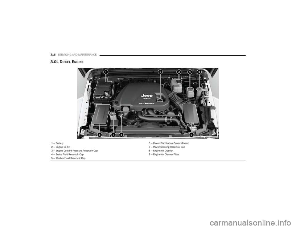
3.0L DIESEL ENGINE
1 — Battery 6 — Power Distribution Center (Fuses)
2 — Engine Oil Fill 7 — Power Steering Reservoir Cap
3 — Engine Coolant Pressure Reservoir Cap 8 — Engine Oil Dipstick
4 — Brake Fluid Reservoir Cap 9 — Engine Air Cleaner Filter
5 — Washer Fluid Reservoir Cap
23_JL_OM_EN_USC_t.book Page 316
Page 336 of 396
334SERVICING AND MAINTENANCE
The fuses protect electrical systems against excessive
current.
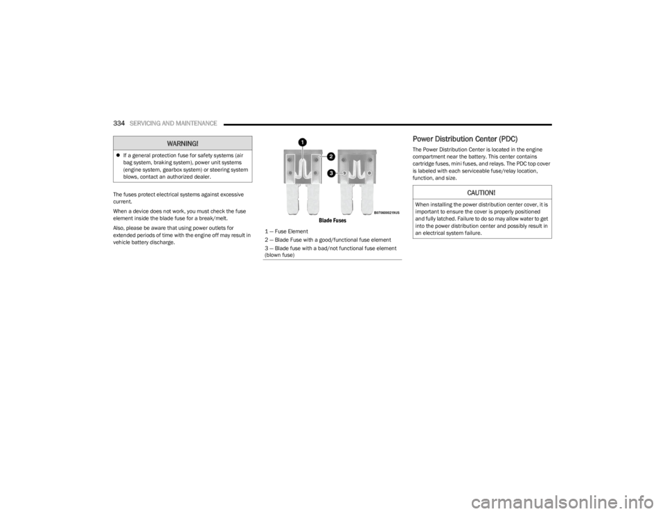
When a device does not work, you must check the fuse
element inside the blade fuse for a break/melt.
Also, please be aware that using power outlets for
extended periods of time with the engine off may result in
vehicle battery discharge.
Blade Fuses
Power Distribution Center (PDC)
The Power Distribution Center is located in the engine
compartment near the battery. This center contains
cartridge fuses, mini fuses, and relays. The PDC top cover
is labeled with each serviceable fuse/relay location,
function, and size.
If a general protection fuse for safety systems (air
bag system, braking system), power unit systems
(engine system, gearbox system) or steering system
blows, contact an authorized dealer.WARNING!
1 — Fuse Element
2 — Blade Fuse with a good/functional fuse element
3 — Blade fuse with a bad/not functional fuse element
(blown fuse)
CAUTION!
When installing the power distribution center cover, it is
important to ensure the cover is properly positioned
and fully latched. Failure to do so may allow water to get
into the power distribution center and possibly result in
an electrical system failure.
23_JL_OM_EN_USC_t.book Page 334
Page 340 of 396
338SERVICING AND MAINTENANCE
F25 –10 Amp RedModule Shift By Wire (MOD_SBW)
F26 40 Amp Green –Central Body Controller (CBC) 2-EXTERIOR LIGHTS #1
F27 30 Amp Pink –Front Wipers
F28 40 Amp Green –Central Body Controller (CBC) 3-POWER LOCKS
F29 40 Amp Green –Central Body Controller (CBC) 4-EXTERIOR LIGHTS #2
F30 ––Spare *
F31 –10 Amp RedDIAGNOSTIC PORT
F32 –10 Amp RedHeating Ventilation Air Conditioning Mod (HVAC CTRL MOD)/Steering
Column Lock (SCL)/Occupant Classification Module (OCM)/Driver
Presence Detection Module (DPDM)
F33 –10 Amp RedParkTronics System (PTS)/Infrared Camera Module (IRCM)/Airbag
Disable Lamps (AIRBAG DISABLE LMPS)
F34 –10 Amp RedElectronic Stability Control (ESC)/Electric Hydraulic Power Steering
(EHPS)/Smart Bar Control Module (SBCM) WAKE UP
F35 30 Amp Pink –BRAKE VAC PMP*
F36 30 Amp Pink –TRAILER TOW ELEC BRK MOD*
F37 30 Amp Pink –TRAILER TOW CONN 7W*
F38 20 Amp Blue –Engine Control Module (ECM)
F39 –15 Amp BlueMGU Coolant Pump (3.6)*
F40 –15 Amp BlueDriveTrain Control Module (DTCM)/Axle Lock (AXLE LOC) FT_RR
F41 –15 Amp BlueInstrument Cluster (IC)/Security GateWay (SGW) WAKE UP
F42 –10 Amp RedPCR Ctrl Feed (ESS) *
F43 –20 Amp Yellow PWR OUTLET (CARGO) BATT
F44 –10 Amp RedInfraRed Camera (IRCAM) HEATERS
F45 –20 Amp Yellow PWR OUTLET (CARGO) IGN
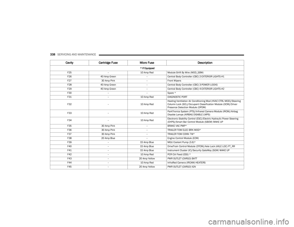
CavityCartridge Fuse Micro Fuse Description
* If Equipped
23_JL_OM_EN_USC_t.book Page 338
Page 341 of 396
SERVICING AND MAINTENANCE339
F46 –10 Amp RedAUTO HDLP LVL MOD/LVL MTR/HDLP SW
F47 ––Spare *
F48 ––Spare *
F49 –10 Amp RedOccupant Restraint Controller (ORC)
F50 –10 Amp RedHD ACC*
F51 –10 Amp RedDigital TV Inline / USB / ISRVM / Compass Mod
F52 –20 Amp Yellow CIGAR LTR
F53 ––Spare *
F54 ––Spare *
F55 –10 Amp RedCentral Vision Processing Module (CVPM)
F56 –10 Amp RedIN-CAR TEMP SENSOR/PTC HTR COIL FEED
F57 –20 Amp Yellow Driver Heated Seat
F58 –20 Amp Yellow Pass Heated Seat
F59 ––Spare *
F60 –15 Amp BlueComfort Steering Wheel Module (CSWM) (HTD STR WHEEL)
F61 –10 Amp RedLeft Blind Spot Sensor (LBSS)/Right Blind Spot Sensor (RBSS)
F62 ––
Spare *
10 Amp Red Exhaust Sol *
F63 –10 Amp RedOccupant Restraint Controller (ORC)
F64 ––Spare *
F65 ––Spare *
F66 40 Amp Green –HVAC BLOWER MTR Front
F67 ––Spare *
F68 ––Spare *
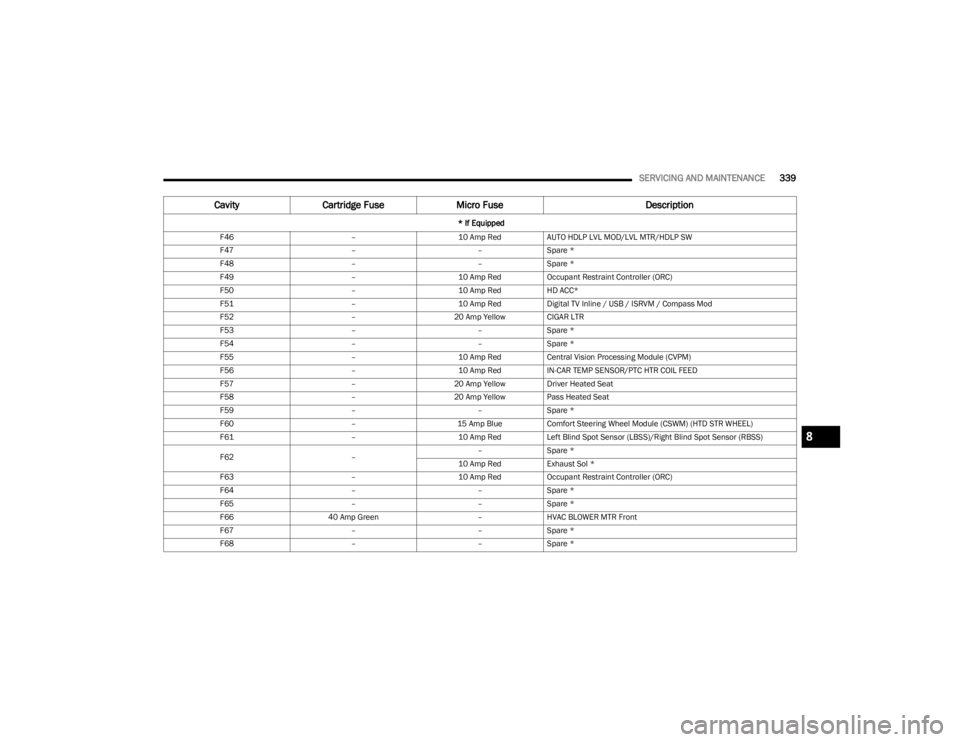
Cavity Cartridge Fuse Micro Fuse Description
* If Equipped
8
23_JL_OM_EN_USC_t.book Page 339
Page 342 of 396
340SERVICING AND MAINTENANCE
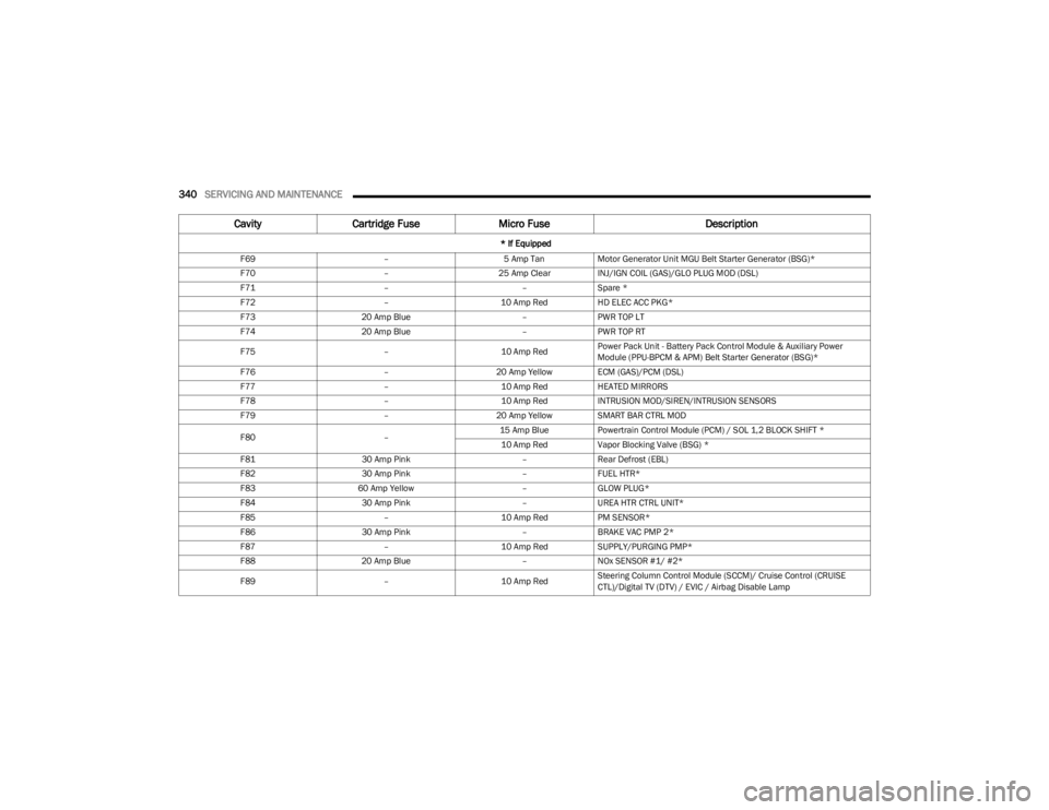
F69 –5 Amp TanMotor Generator Unit MGU Belt Starter Generator (BSG)*
F70 –25 Amp ClearINJ/IGN COIL (GAS)/GLO PLUG MOD (DSL)
F71 ––Spare *
F72 –10 Amp RedHD ELEC ACC PKG*
F73 20 Amp Blue –PWR TOP LT
F74 20 Amp Blue –PWR TOP RT
F75 –10 Amp RedPower Pack Unit - Battery Pack Control Module & Auxiliary Power
Module (PPU-BPCM & APM) Belt Starter Generator (BSG)*
F76 –20 Amp Yellow ECM (GAS)/PCM (DSL)
F77 –10 Amp RedHEATED MIRRORS
F78 –10 Amp RedINTRUSION MOD/SIREN/INTRUSION SENSORS
F79 –20 Amp Yellow SMART BAR CTRL MOD
F80 –15 Amp Blue
Powertrain Control Module (PCM) / SOL 1,2 BLOCK SHIFT *
10 Amp Red Vapor Blocking Valve (BSG) *
F81 30 Amp Pink –Rear Defrost (EBL)
F82 30 Amp Pink –FUEL HTR*
F83 60 Amp Yellow –GLOW PLUG*
F84 30 Amp Pink –UREA HTR CTRL UNIT*
F85 –10 Amp RedPM SENSOR*
F86 30 Amp Pink –BRAKE VAC PMP 2*
F87 –10 Amp RedSUPPLY/PURGING PMP*
F88 20 Amp Blue –NOx SENSOR #1/ #2*
F89 –10 Amp RedSteering Column Control Module (SCCM)/ Cruise Control (CRUISE
CTL)/Digital TV (DTV) / EVIC / Airbag Disable Lamp
Cavity
Cartridge Fuse Micro Fuse Description
* If Equipped
23_JL_OM_EN_USC_t.book Page 340
Page 354 of 396
352SERVICING AND MAINTENANCE
(Continued)
TIRES — GENERAL INFORMATION
Tire Pressure
Proper tire inflation pressure is essential to the safe and
satisfactory operation of your vehicle. Four primary areas
are affected by improper tire pressure:
Safety
Fuel Economy
Tread Wear
Ride Comfort and Vehicle Stability
Safety Both underinflation and overinflation affect the stability of
the vehicle and can produce a feeling of sluggish response
or over responsiveness in the steering.
NOTE:
Unequal tire pressures from side to side may cause
erratic and unpredictable steering response.
Unequal tire pressure from side to side may cause the
vehicle to drift left or right.
Fuel Economy
Underinflated tires will increase tire rolling resistance
resulting in higher fuel consumption.
Tread Wear
Improper cold tire inflation pressures can cause abnormal
wear patterns and reduced tread life, resulting in the need
for earlier tire replacement.
Ride Comfort And Vehicle Stability
Proper tire inflation contributes to a comfortable ride.
Overinflation produces a jarring and uncomfortable ride.
Tire Inflation Pressures
The proper cold tire inflation pressure is listed on the
driver's side B-pillar or rear edge of the driver's side door. At least once a month:
Check and adjust tire pressure with a good quality
pocket-type pressure gauge. Do not make a visual
judgement when determining proper inflation. Tires
may look properly inflated even when they are
under-inflated.
Inspect tires for signs of tire wear or visible damage.
Inflation pressures specified on the placard are always
“cold tire inflation pressure”. Cold tire inflation pressure is
defined as the tire pressure after the vehicle has not been
driven for at least three hours, or driven less than 1 mile
(1.6 km) after sitting for a minimum of three hours. The
cold tire inflation pressure must not exceed the maximum
inflation pressure molded into the tire sidewall.
Check tire pressures more often if subject to a wide range
of outdoor temperatures, as tire pressures vary with
temperature changes.
Tire pressures change by approximately 1 psi (7 kPa) per
12°F (7°C) of air temperature change. Keep this in mind
when checking tire pressure inside a garage, especially in
the Winter.
WARNING!
Improperly inflated tires are dangerous and can
cause collisions.
Underinflation increases tire flexing and can result in
overheating and tire failure.
Overinflation reduces a tire's ability to cushion shock.
Objects on the road and chuckholes can cause
damage that result in tire failure.
Overinflated or underinflated tires can affect vehicle
handling and can fail suddenly, resulting in loss of
vehicle control.
Unequal tire pressures can cause steering problems.
You could lose control of your vehicle.
Unequal tire pressures from one side of the vehicle
to the other can cause the vehicle to drift to the right
or left.
Always drive with each tire inflated to the recom -
mended cold tire inflation pressure.
WARNING!
CAUTION!
After inspecting or adjusting the tire pressure, always
reinstall the valve stem cap. This will prevent moisture
and dirt from entering the valve stem, which could
damage the valve stem.
23_JL_OM_EN_USC_t.book Page 352
Page 356 of 396
354SERVICING AND MAINTENANCE
(Continued)
Tread Wear Indicators
Tread wear indicators are in the original equipment tires to
help you in determining when your tires should be
replaced.
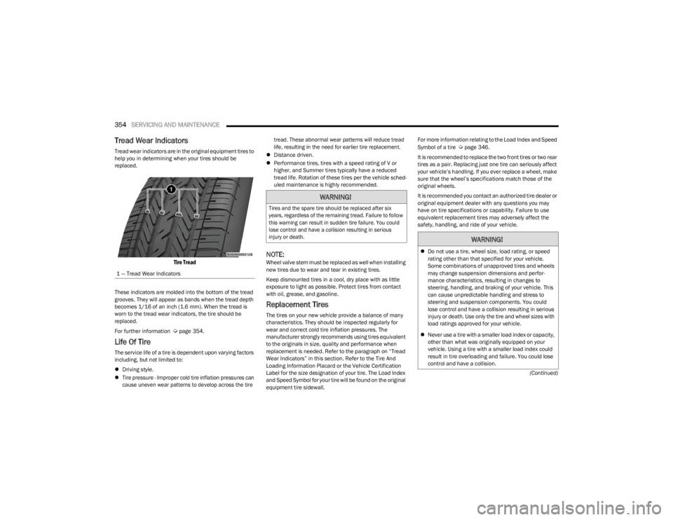
Tire Tread
These indicators are molded into the bottom of the tread
grooves. They will appear as bands when the tread depth
becomes 1/16 of an inch (1.6 mm). When the tread is
worn to the tread wear indicators, the tire should be
replaced.
For further information
Úpage 354.
Life Of Tire
The service life of a tire is dependent upon varying factors
including, but not limited to:
Driving style.
Tire pressure - Improper cold tire inflation pressures can
cause uneven wear patterns to develop across the tire tread. These abnormal wear patterns will reduce tread
life, resulting in the need for earlier tire replacement.
Distance driven.
Performance tires, tires with a speed rating of V or
higher, and Summer tires typically have a reduced
tread life. Rotation of these tires per the vehicle sched-
uled maintenance is highly recommended.
NOTE:Wheel valve stem must be replaced as well when installing
new tires due to wear and tear in existing tires.
Keep dismounted tires in a cool, dry place with as little
exposure to light as possible. Protect tires from contact
with oil, grease, and gasoline.
Replacement Tires
The tires on your new vehicle provide a balance of many
characteristics. They should be inspected regularly for
wear and correct cold tire inflation pressures. The
manufacturer strongly recommends using tires equivalent
to the originals in size, quality and performance when
replacement is needed. Refer to the paragraph on “Tread
Wear Indicators” in this section. Refer to the Tire And
Loading Information Placard or the Vehicle Certification
Label for the size designation of your tire. The Load Index
and Speed Symbol for your tire will be found on the original
equipment tire sidewall. For more information relating to the Load Index and Speed
Symbol of a tire
Úpage 346.
It is recommended to replace the two front tires or two rear
tires as a pair. Replacing just one tire can seriously affect
your vehicle’s handling. If you ever replace a wheel, make
sure that the wheel’s specifications match those of the
original wheels.
It is recommended you contact an authorized tire dealer or
original equipment dealer with any questions you may
have on tire specifications or capability. Failure to use
equivalent replacement tires may adversely affect the
safety, handling, and ride of your vehicle.
1 — Tread Wear Indicators
WARNING!
Tires and the spare tire should be replaced after six
years, regardless of the remaining tread. Failure to follow
this warning can result in sudden tire failure. You could
lose control and have a collision resulting in serious
injury or death.
WARNING!
Do not use a tire, wheel size, load rating, or speed
rating other than that specified for your vehicle.
Some combinations of unapproved tires and wheels
may change suspension dimensions and perfor -
mance characteristics, resulting in changes to
steering, handling, and braking of your vehicle. This
can cause unpredictable handling and stress to
steering and suspension components. You could
lose control and have a collision resulting in serious
injury or death. Use only the tire and wheel sizes with
load ratings approved for your vehicle.
Never use a tire with a smaller load index or capacity,
other than what was originally equipped on your
vehicle. Using a tire with a smaller load index could
result in tire overloading and failure. You could lose
control and have a collision.
23_JL_OM_EN_USC_t.book Page 354
Page 360 of 396
358SERVICING AND MAINTENANCE
TIRE ROTATION RECOMMENDATIONS
The tires on the front and rear of your vehicle operate at
different loads and perform different steering, handling,
and braking functions. For these reasons, they wear at
unequal rates.
These effects can be reduced by timely rotation of tires.
The benefits of rotation are especially worthwhile with
aggressive tread designs such as those on On/Off Road
type tires. Rotation will increase tread life, help to
maintain mud, snow, and wet traction levels, and
contribute to a smooth, quiet ride.
For the proper maintenance intervals
Úpage 307. The
reasons for any rapid or unusual wear should be corrected
prior to rotation being performed.
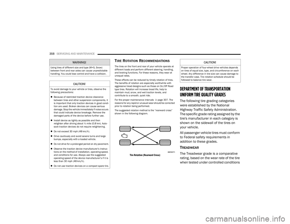
The suggested rotation method is the “rearward cross”
shown in the following diagram.
Tire Rotation (Rearward Cross)
DEPARTMENT OF TRANSPORTATION
UNIFORM TIRE QUALITY GRADES
The following tire grading categories
were established by the National
Highway Traffic Safety Administration.
The specific grade rating assigned by the
tire's manufacturer in each category is
shown on the sidewall of the tires on
your vehicle.
All passenger vehicle tires must conform
to Federal safety requirements in
addition to these grades.
TREADWEAR
The Treadwear grade is a comparative
rating, based on the wear rate of the tire
when tested under controlled conditions
WARNING!
Using tires of different size and type (M+S, Snow)
between front and rear axles can cause unpredictable
handling. You could lose control and have a collision.
CAUTION!
To avoid damage to your vehicle or tires, observe the
following precautions:
Because of restricted traction device clearance
between tires and other suspension components, it
is important that only traction devices in good condi -
tion are used. Broken devices can cause serious
damage. Stop the vehicle immediately if noise occurs
that could indicate device breakage. Remove the
damaged parts of the device before further use.
Install device as tightly as possible and then
retighten after driving about ½ mile (0.8 km). Auto -
sock traction devices do not require retightening.
Do not exceed 30 mph (48 km/h).
Drive cautiously and avoid severe turns and large
bumps, especially with a loaded vehicle.
Do not drive for a prolonged period on dry pavement.
Observe the traction device manufacturer’s instruc -
tions on the method of installation, operating speed,
and conditions for use. Always use the suggested
operating speed of the device manufacturer’s if it is
less than 30 mph (48 km/h).
Do not use traction devices on a compact spare tire.
CAUTION!
Proper operation of four-wheel drive vehicles depends
on tires of equal size, type, and circumference on each
wheel. Any difference in tire size can cause damage to
the transfer case. Tire rotation schedule should be
followed to balance tire wear.
23_JL_OM_EN_USC_t.book Page 358
Page 378 of 396
376TECHNICAL SPECIFICATIONS
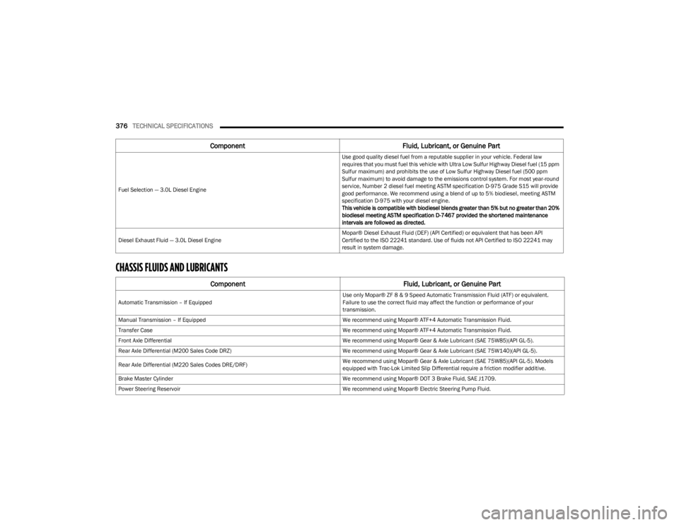
CHASSIS FLUIDS AND LUBRICANTS
Fuel Selection — 3.0L Diesel Engine Use good quality diesel fuel from a reputable supplier in your vehicle. Federal law
requires that you must fuel this vehicle with Ultra Low Sulfur Highway Diesel fuel (15 ppm
Sulfur maximum) and prohibits the use of Low Sulfur Highway Diesel fuel (500 ppm
Sulfur maximum) to avoid damage to the emissions control system. For most year-round
service, Number 2 diesel fuel meeting ASTM specification D-975 Grade S15 will provide
good performance. We recommend using a blend of up to 5% biodiesel, meeting ASTM
specification D-975 with your diesel engine.
This vehicle is compatible with biodiesel blends greater than 5% but no greater than 20%
biodiesel meeting ASTM specification D-7467 provided the shortened maintenance
intervals are followed as directed.
Diesel Exhaust Fluid — 3.0L Diesel Engine Mopar® Diesel Exhaust Fluid (DEF) (API Certified) or equivalent that has been API
Certified to the ISO 22241 standard. Use of fluids not API Certified to ISO 22241 may
result in system damage.
Component
Fluid, Lubricant, or Genuine Part
Automatic Transmission – If Equipped Use only Mopar® ZF 8 & 9 Speed Automatic Transmission Fluid (ATF) or equivalent.
Failure to use the correct fluid may affect the function or performance of your
transmission.
Manual Transmission – If Equipped We recommend using Mopar® ATF+4 Automatic Transmission Fluid.
Transfer Case We recommend using Mopar® ATF+4 Automatic Transmission Fluid.
Front Axle Differential We recommend using Mopar® Gear & Axle Lubricant (SAE 75W85)(API GL-5).
Rear Axle Differential (M200 Sales Code DRZ) We recommend using Mopar® Gear & Axle Lubricant (SAE 75W140)(API GL-5).
Rear Axle Differential (M220 Sales Codes DRE/DRF) We recommend using Mopar® Gear & Axle Lubricant (SAE 75W85)(API GL-5). Models
equipped with Trac-Lok Limited Slip Differential require a friction modifier additive.
Brake Master Cylinder We recommend using Mopar® DOT 3 Brake Fluid, SAE J1709.
Power Steering Reservoir We recommend using Mopar® Electric Steering Pump Fluid.
ComponentFluid, Lubricant, or Genuine Part
23_JL_OM_EN_USC_t.book Page 376
Page 387 of 396
385
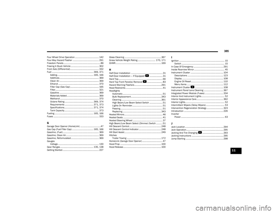
Four Wheel Drive Operation ........................................ 142
Four-Way Hazard Flasher ............................................ 291
Freedom Panels .............................................................. 86
Freeing A Stuck Vehicle ............................................... 302
Front Axle (Differential) ................................................ 332
Fuel ...................................................................... 369
, 371
Adding............................................................. 165, 166
Additives .................................................................. 369
Clean Air .................................................................. 369
Ethanol .................................................................... 370
Filler Cap (Gas Cap) ................................................ 165
Filter......................................................................... 321
Gasoline .................................................................. 369
Materials Added...................................................... 369
Methanol ................................................................. 370
Octane Rating ................................................ 369
, 374
Requirements ................................................ 371, 373
Specifications................................................. 371, 374
Tank Capacity.......................................................... 373
Fueling ................................................................. 165
, 166
Fuses ............................................................................ 333
GGarage Door Opener (HomeLink) ..................................47
Gas Cap (Fuel Filler Cap) .................................... 165, 166
Gasoline, (Fuel) ............................................................ 369
Gasoline, Clean Air ....................................................... 369
Gasoline, Reformulated............................................... 369
Gauges Voltage..................................................................... 130
Gear Ranges ........................................................ 135
, 138
Getting Started ............................................................. 227 Glass Cleaning .............................................................. 367
Gross Vehicle Weight Rating .............................. 170
, 171
GVWR.............................................................................169
HHalf-Door Installation ..................................................... 31 Half-Door Installation — If Equipped
S
...................... 31
Hard Top .......................................................................... 66 Hard Top Front Panel(s) Removal
S
.......................... 83
Hazard Warning Flashers ............................................. 291
Head Restraints .............................................................. 41
Headlights Automatic ................................................................... 51
Bulb Replacement...................................................343
Cleaning ...................................................................361High Beam/Low Beam Select Switch ...................... 51
Lights On Reminder................................................... 51
Passing....................................................................... 51
Replacing ................................................................. 343
Heated Mirrors ................................................................ 46
Heated Seats .................................................................. 41
Heated Steering Wheel .................................................. 37
High Beam/Low Beam Select (Dimmer) Switch ........... 51
Hill Descent Control ...................................................... 248
Hill Descent Control Indicator ...................................... 248
Hill Start Assist .............................................................. 249
Hitches Trailer Towing .......................................................... 172
HomeLink (Garage Door Opener) .................................. 47
Hood Prop .....................................................................100
Hood Release................................................................ 100
IIgnition ............................................................................ 15 Switch ........................................................................ 15
In Case Of Emergency .................................................. 291
Inside Rearview Mirror ................................................... 45
Instrument Cluster ....................................................... 104 Descriptions ............................................................ 123
Display ..................................................................... 108Engine Oil Reset ...................................................... 110
Menu Items ............................................................. 112
Instrument Cluster
S
................................................ 108
Instrument Panel Lens Cleaning ................................. 367
Integrated Power Module (Fuses) ............................... 334
Interior And Instrument Lights....................................... 52
Interior Appearance Care............................................. 362
Interior Lights.................................................................. 52
Intermittent Wipers (Delay Wipers) ............................... 53
Intervention Regeneration Strategy ............................ 323
Introduction .................................................................. 226
Inverter Power ......................................................................... 63
JJack Location ................................................................ 294
Jack Operation.............................................................. 295
Jacking And Tire Changing
S
................................... 293
Jacking Instructions ..................................................... 295
Jump Starting ............................................................... 298
11
23_JL_OM_EN_USC_t.book Page 385