brake sensor JEEP WRANGLER 2023 Owners Manual
[x] Cancel search | Manufacturer: JEEP, Model Year: 2023, Model line: WRANGLER, Model: JEEP WRANGLER 2023Pages: 396, PDF Size: 25.15 MB
Page 6 of 396

4
NORMAL OPERATION — DIESEL ENGINE ..................... 130
Cold Weather Precautions........................................ 131Engine Idling .............................................................. 131Stopping The Engine ................................................. 132
Cooling System Tips — Automatic Transmission..... 132
ENGINE BREAK-IN RECOMMENDATIONS —
GASOLINE ENGINE (IF EQUIPPED) ................................ 133
ENGINE BREAK-IN RECOMMENDATIONS — DIESEL
ENGINE (IF EQUIPPED) .................................................... 133
PARKING BRAKE ............................................................. 133
MANUAL TRANSMISSION — IF EQUIPPED .................... 134 Shifting....................................................................... 135
Downshifting.............................................................. 136
AUTOMATIC TRANSMISSION — IF EQUIPPED .............. 137 Ignition Park Interlock............................................... 137Brake/Transmission Shift Interlock (BTSI)
System ...................................................................... 138
8–Speed Automatic Transmission .......................... 138
FOUR–WHEEL DRIVE OPERATION ............................... 140 Four-Position Transfer Case — If Equipped ............ 141Five-Position Transfer Case — If Equipped .............. 142
Trac-Lok Rear Axle — If Equipped ............................ 144
Axle Lock (Tru-Lok) Front And Rear — If Equipped ... 144
Axle Lock (Tru-Lok) Rear Only — If Equipped .......... 144
Electronic Sway Bar Disconnect — If Equipped ...... 145
Off Road+ — If Equipped........................................... 146
ELECTRO-HYDRAULIC POWER STEERING .................... 146
STOP/START SYSTEM — AUTOMATIC TRANSMISSION
(IF EQUIPPED) .................................................................. 147 Autostop Mode .......................................................... 147
Possible Reasons The Engine Does Not Autostop.. 148
To Start The Engine While In Autostop Mode.......... 148
To Manually Turn Off The Stop/Start System ......... 148
To Manually Turn On The Stop/Start System.......... 149
System Malfunction .................................................. 149 STOP/START SYSTEM — MANUAL TRANSMISSION
(IF EQUIPPED) .................................................................. 149
Autostop Mode.......................................................... 149
Possible Reasons The Engine Does Not
Autostop .................................................................... 150
To Start The Engine While In Autostop Mode ......... 150
To Manually Turn Off The Stop/Start System ......... 150
To Manually Turn On The Stop/Start System ......... 151
System Malfunction.................................................. 151
CRUISE CONTROL SYSTEMS — IF EQUIPPED ............. 151 Cruise Control ........................................................... 151
Adaptive Cruise Control (ACC).................................. 152
PARKSENSE REAR PARK ASSIST — IF EQUIPPED ...... 160 ParkSense Sensors .................................................. 160ParkSense Warning Display ..................................... 160
ParkSense Display.................................................... 160
Enabling And Disabling ParkSense ......................... 162
Service The ParkSense Rear Park Assist System... 162
Cleaning The ParkSense System ............................. 163ParkSense System Usage Precautions ................... 163
PARKVIEW REAR BACK UP CAMERA ........................... 163
TRAILCAM SYSTEM — IF EQUIPPED .............................. 164
REFUELING THE VEHICLE — GASOLINE ENGINE
(IF EQUIPPED) .................................................................. 165 Fuel Filler Cap ........................................................... 165
Loose Fuel Filler Cap Message ............................... 166
REFUELING THE VEHICLE — DIESEL ENGINE
(IF EQUIPPED) .................................................................. 166 Avoid Using Contaminated Fuel............................... 167
Bulk Fuel Storage — Diesel Fuel .............................. 167
Diesel Exhaust Fluid ................................................. 167
VEHICLE LOADING ........................................................... 169 Certification Label..................................................... 169 TRAILER TOWING ............................................................170
Common Towing Definitions..................................... 170
Trailer Hitch Classification ........................................ 172Trailer Towing Weights (Maximum Trailer Weight
Ratings) ..................................................................... 172
Trailer And Tongue Weight........................................ 173Towing Requirements ............................................... 173Towing Tips ................................................................ 175
RECREATIONAL TOWING (BEHIND MOTORHOME) ...... 176 Towing This Vehicle Behind Another Vehicle ........... 176Recreational Towing — Four-Wheel Drive Models ... 176
DRIVING TIPS ....................................................................178 On-Road Driving Tips ................................................. 178
Off-Road Driving Tips................................................. 178
MULTIMEDIA
UCONNECT SYSTEMS ......................................................184
CYBERSECURITY ..............................................................184
UCONNECT SETTINGS ......................................................184 Customer Programmable Features ......................... 184
UCONNECT INTRODUCTION ............................................ 197 System Overview ...................................................... 197Drag & Drop Menu Bar ............................................. 200Safety And General Information ............................... 200
UCONNECT MODES .......................................................... 201 Steering Wheel Audio Controls ................................ 201Radio Mode .............................................................. 201
Media Mode .............................................................. 210
Phone Mode ............................................................. 212
23_JL_OM_EN_USC_t.book Page 4
Page 129 of 396
STARTING AND OPERATING127
seconds (or three short pushes in a row) to turn the
engine off. The ignition will remain in the ACC position
(NOT the OFF position) if the engine is turned off when
the transmission is not in PARK.
NOTE:The system will automatically time out and the ignition will
cycle to the OFF position after 30 minutes of inactivity if
the ignition is left in the ACC or RUN (engine not running)
position and the transmission is in PARK.
ENGINE START/STOP Button Functions — With Driver’s
Foot OFF The Brake Pedal (In PARK Or NEUTRAL Position)
The ENGINE START/STOP button operates similar to an
ignition switch. It has three positions: OFF, ACC, and RUN.
To change the ignition positions without starting the
vehicle and use the accessories, follow these steps:
1. Start with the ignition in the OFF position.
2. Push the ENGINE START/STOP button once to place
the ignition to the ACC position (instrument cluster
will display “ACC”).
3. Push the ENGINE START/STOP button a second time to place the ignition to the RUN position (instrument
cluster will display “ON/RUN”).
4. Push the ENGINE START/STOP button a third time to return the ignition to the OFF position (instrument
cluster will display “OFF”).
AUTOPARK
AutoPark is a supplemental feature to assist with placing
the vehicle in PARK should the situations on the following
pages occur. It is a back-up system and should not be relied upon as the primary method by which the driver
shifts the vehicle into PARK.
The conditions under which AutoPark will engage are
outlined on the following pages.
If the vehicle is not in PARK and the driver turns off the
engine, the vehicle may AutoPark.
AutoPark will engage when all of these conditions are met:
Vehicle is equipped with an 8-speed transmission
Driver’s door is ajar or if the driver’s door is removed
and the driver is not on the seat (seat pad sensor
detects driver missing)
Vehicle is not in PARK
Vehicle speed is 1.2 mph (1.9 km/h) or less
Ignition is switched from RUN to OFF
NOTE:For Keyless Enter ‘n Go™ equipped vehicles, the engine
will turn off and the ignition switch will change to ACC
position.
If the vehicle is not in PARK and the driver exits the vehicle
with the engine running, the vehicle may AutoPark.
AutoPark will engage when all of these conditions are met:
Vehicle is equipped with an 8-speed transmission
Driver’s door is ajar or if the driver’s door is removed
and the driver is not on the seat (seat pad sensor
detects driver missing)
Vehicle is not in PARK
Vehicle speed is 1.2 mph (1.9 km/h) or less
Driver’s seat belt is unbuckled
Brake pedal is not pressed
The message “ AutoPark Engaged Shift To P Then Shift To
Gear ” will display in the instrument cluster.
NOTE:In some cases the ParkSense graphic will be displayed in
the instrument cluster. In these cases, the gear selector
must be returned to “P” to select desired gear.
If the driver shifts into PARK while moving, the vehicle may
AutoPark.
AutoPark will engage ONLY when vehicle speed is 1.2 mph
(1.9 km/h) or less.
The message “ Vehicle Speed Is Too High To Shift To P ” will
be displayed in the instrument cluster if vehicle speed is
above 1.2 mph (1.9 km/h).
WARNING!
Driver inattention could lead to failure to place the
vehicle in PARK. ALWAYS DO A VISUAL CHECK that
your vehicle is in PARK by verifying that a solid (not
blinking) “P” is indicated in the instrument cluster
display and on the gear selector. If the "P" indicator is
blinking, your vehicle is not in PARK. As an added
precaution, always apply the parking brake when
exiting the vehicle.
AutoPark is a supplemental feature. It is not
designed to replace the need to shift your vehicle
into PARK. It is a back-up system and should not be
relied upon as the primary method by which the
driver shifts the vehicle into PARK.
4
23_JL_OM_EN_USC_t.book Page 127
Page 154 of 396
152STARTING AND OPERATING
To Set A Desired Speed
Turn the Cruise Control on.
NOTE:The vehicle should be traveling at a steady speed and on
level ground before pushing the SET (+) or SET (-) button.
When the vehicle has reached the desired speed, push
the SET (+) or SET (-) button and release. Release the
accelerator and the vehicle will operate at the selected
speed.
To Vary The Speed Setting
To Increase Or Decrease The Set Speed
When the Cruise Control is set, you can increase speed by
pushing the SET (+) button, or decrease speed by pushing
the SET (-) button.
U.S. Speed (mph)
Pushing the SET (+), or SET (-) button once will result in
a 1 mph speed adjustment. Each subsequent tap of
the button results in an adjustment of 1 mph.
If the button is continually pushed, the set speed will
continue to adjust in 5 mph increments until the button
is released, then the new set speed will be established.
Metric Speed (km/h)
Pushing the SET (+), or SET (-) button once will result in
a 1 km/h speed adjustment. Each subsequent tap of
the button results in an adjustment of 1 km/h.
If the button is continually pushed, the set speed will
continue to adjust in 10 km/h increments until the
button is released, then the new set speed will be
established.
To Accelerate For Passing
While the Cruise Control is set, press the accelerator to
pass as you would normally. When the pedal is released,
the vehicle will return to the set speed.
USING CRUISE CONTROL ON HILLS
The transmission may downshift on hills to maintain the
vehicle set speed.
The Cruise Control system maintains speed up and down
hills. A slight speed change on moderate hills is normal.
On steep hills, a greater speed loss or gain may occur so it
may be preferable to drive without Cruise Control.
To Resume Speed
To resume a previously set speed, push the RES button
and release. Resume can be used at any speed above
20 mph (32 km/h).
To Deactivate
A tap on the brake pedal, pushing the CANC (cancel)
button, or normal brake pressure while slowing the vehicle
will deactivate the Cruise Control without erasing the set
speed from memory. The following conditions will also deactivate the Cruise
Control without erasing the set speed from memory:
Vehicle parking brake is applied
Stability event occurs
Gear selector is moved out of DRIVE
Engine overspeed occurs
Clutch pedal is pressed (manual transmission only)
Vehicle is operating at a low RPM (manual transmis -
sion only)
Pushing the on/off button or placing the ignition in the OFF
position erases the set speed from memory.
ADAPTIVE CRUISE CONTROL (ACC)
Adaptive Cruise Control (ACC) increases the driving
convenience provided by Cruise Control while traveling on
highways and major roadways. However, it is not a safety
system and not designed to prevent collisions. The Cruise
Control function performs differently if your vehicle is not
equipped with ACC
Úpage 151.
NOTE:
If the ACC sensor detects a vehicle ahead, ACC will
apply limited braking or accelerate (not to exceed the
original set speed) automatically to maintain a preset
following distance, while matching the speed of the
vehicle ahead.
Any chassis/suspension or tire size modifications to
the vehicle will affect the performance of the Adaptive
Cruise Control and Forward Collision Warning system.
Fixed Speed Cruise Control (ACC not enabled) will not
detect vehicles directly ahead of you. Always be aware
of the feature selected
Úpage 381.
WARNING!
Cruise Control can be dangerous where the system
cannot maintain a constant speed. Your vehicle could
go too fast for the conditions, and you could lose control
and have an accident. Do not use Cruise Control in
heavy traffic or on roads that are winding, icy,
snow-covered or slippery.
23_JL_OM_EN_USC_t.book Page 152
Page 158 of 396
156STARTING AND OPERATING
U.S. Speed (mph)
Pushing the SET (+), or SET (-) button once will result in
a 1 mph speed adjustment. Each subsequent tap of
the button results in an adjustment of 1 mph.
If the button is continually pushed, the set speed will
continue to adjust in 5 mph increments until the button
is released. The new set speed is reflected in the instru -
ment cluster display.
Metric Speed (km/h)
Pushing the SET (+), or SET (-) button once will result in
a 1 km/h speed adjustment. Each subsequent tap of
the button results in an adjustment of 1 km/h.
If the button is continually pushed, the set speed will
continue to adjust in 10 km/h increments until the
button is released. The new set speed is reflected in
the instrument cluster display.
NOTE:When you override and push the SET (+) button or SET (-)
buttons, the new set speed will be the current speed of the
vehicle.
When ACC Is Active
When you use the SET (-) button to decelerate, if the
engine’s braking power does not slow the vehicle suffi -
ciently to reach the set speed, the brake system will
automatically slow the vehicle.
The ACC system applies the brake down to a full stop
when following the vehicle in front. If your vehicle
follows the vehicle in front to a standstill, your vehicle
will release the brakes two seconds after coming to a
full stop.
The ACC system maintains set speed when driving
uphill and downhill. However, a slight speed change on moderate hills is normal. In addition, downshifting may
occur while climbing uphill or descending downhill. This
is normal operation and necessary to maintain set
speed. When driving uphill and downhill, the ACC
system will cancel if the braking temperature exceeds
normal range (overheated).
Setting The Following Distance In ACC
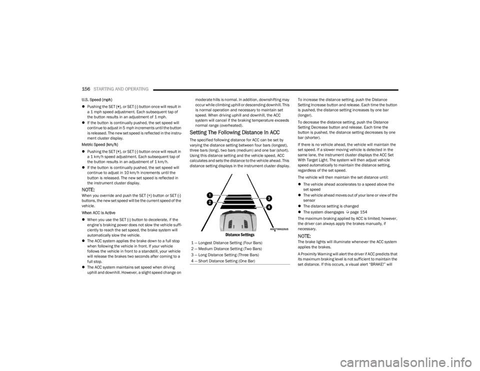
The specified following distance for ACC can be set by
varying the distance setting between four bars (longest),
three bars (long), two bars (medium) and one bar (short).
Using this distance setting and the vehicle speed, ACC
calculates and sets the distance to the vehicle ahead. This
distance setting displays in the instrument cluster display.
Distance Settings
To increase the distance setting, push the Distance
Setting Increase button and release. Each time the button
is pushed, the distance setting increases by one bar
(longer).
To decrease the distance setting, push the Distance
Setting Decrease button and release. Each time the
button is pushed, the distance setting decreases by one
bar (shorter).
If there is no vehicle ahead, the vehicle will maintain the
set speed. If a slower moving vehicle is detected in the
same lane, the instrument cluster displays the ACC Set
With Target Light. The system will then adjust vehicle
speed automatically to maintain the distance setting,
regardless of the set speed.
The vehicle will then maintain the set distance until:
The vehicle ahead accelerates to a speed above the
set speed
The vehicle ahead moves out of your lane or view of the
sensor
The distance setting is changed
The system disengages
Úpage 154
The maximum braking applied by ACC is limited; however,
the driver can always apply the brakes manually, if
necessary.
NOTE:The brake lights will illuminate whenever the ACC system
applies the brakes.
A Proximity Warning will alert the driver if ACC predicts that
its maximum braking level is not sufficient to maintain the
set distance. If this occurs, a visual alert “BRAKE!” will
1 — Longest Distance Setting (Four Bars)
2 — Medium Distance Setting (Two Bars)
3 — Long Distance Setting (Three Bars)
4 — Short Distance Setting (One Bar)
23_JL_OM_EN_USC_t.book Page 156
Page 159 of 396
STARTING AND OPERATING157
flash in the instrument cluster display and a chime will
sound while ACC continues to apply its maximum braking
capacity.
NOTE:The “BRAKE!” screen in the instrument cluster display is a
warning for the driver to take action and does not neces -
sarily mean that the Forward Collision Warning system is
applying the brakes autonomously.
Overtake Aid
When driving with ACC engaged and following a vehicle,
the system will provide an additional acceleration up to
the ACC set speed to assist in passing the vehicle. This
additional acceleration is triggered when the driver utilizes
the left turn signal and will only be active when passing on
the left hand side.
ACC Operation At A Stop (Automatic
Transmission Only)
In the event that the ACC system brings your vehicle to a
standstill while following a target vehicle, your vehicle will
resume motion without the need for any driver action if the
target vehicle starts moving within two seconds of your
vehicle coming to a standstill.
If the target vehicle does not start moving within two
seconds of your vehicle coming to a standstill, the ACC
with Stop system will cancel and the brakes will release. A
cancel message will display on the instrument cluster
display and produce a warning chime. Driver intervention
will be required at this moment.
While ACC with Stop is holding your vehicle at a standstill,
if the driver seatbelt is unbuckled or the driver door is
opened, the ACC with Stop system will cancel and the brakes will release. A cancel message will display on the
instrument cluster display and produce a warning chime.
Driver intervention will be required at this moment.
Display Warnings And Maintenance
“WIPE FRONT RADAR SENSOR IN FRONT OF
VEHICLE” WARNING
The “ACC/FCW Unavailable Wipe Front Radar Sensor”
warning will display and a chime will sound when
conditions temporarily limit system performance.
This most often occurs at times of poor visibility, such as
in snow or heavy rain. The ACC system may also become
temporarily blinded due to obstructions, such as mud, dirt
or ice. In these cases, the instrument cluster display will
display “ACC/FCW Unavailable Wipe Front Radar Sensor”
and the system will deactivate.
The “ACC/FCW Unavailable Wipe Front Radar Sensor”
message can sometimes be displayed while driving in
highly reflective areas (i.e. tunnels with reflective tiles, or
ice and snow). The ACC system will recover after the
vehicle has left these areas. Under rare conditions, when
the radar is not tracking any vehicles or objects in its path
this warning may temporarily occur.
NOTE:If the “ACC/FCW Unavailable Wipe Front Radar Sensor”
warning is active, Fixed Speed Cruise Control is still
available.
If weather conditions are not a factor, the driver should
examine the sensor. It may require cleaning or removal of
an obstruction. The sensor is located in the center of the
vehicle behind the lower grille.
To keep the ACC system operating properly, it is important
to note the following maintenance items:
Always keep the sensor clean. Carefully wipe the
sensor lens with a soft cloth. Be cautious not to
damage the sensor lens.
Do not remove any screws from the sensor. Doing so
could cause an ACC system malfunction or failure and
require a sensor realignment.
If the sensor or front end of the vehicle is damaged due
to a collision, see an authorized dealer for service.
Do not attach or install any accessories near the
sensor, including transparent material or aftermarket
grilles. Doing so could cause an ACC system failure or
malfunction.
When the condition that deactivated the system is no
longer present, the system will return to the “Adaptive
Cruise Control Off” state and will resume function by
simply reactivating it.
NOTE:If the “ACC/FCW Unavailable Wipe Front Radar Sensor”
message occurs frequently (e.g. more than once on every
trip) without any snow, rain, mud, or other obstruction,
have the radar sensor realigned at an authorized dealer.
WARNING!
When the ACC system is resumed, the driver must
ensure that there are no pedestrians, vehicles or
objects in the path of the vehicle. Failure to follow these
warnings can result in a collision and death or serious
personal injury.
4
23_JL_OM_EN_USC_t.book Page 157
Page 248 of 396
246SAFETY
(Continued)
NOTE:ERM is disabled any time the ESC is in “Full Off” mode (if
equipped) Úpage 246.
Electronic Stability Control (ESC)
ESC enhances directional control and stability of the
vehicle under various driving conditions. ESC corrects for
oversteering or understeering of the vehicle by applying
the brake of the appropriate wheel(s) to counteract these
conditions. Engine power may also be reduced to help the
vehicle maintain the desired path.
Oversteer — when the vehicle is turning more than
appropriate for the steering wheel position.
Understeer — when the vehicle is turning less than
appropriate for the steering wheel position.
ESC uses sensors in the vehicle to determine the vehicle
path intended by the driver and compares it to the actual
path of the vehicle. When the actual path does not match
the intended path, ESC applies the brake of the
appropriate wheel to assist in counteracting the oversteer
or understeer condition. The ESC Activation/Malfunction Indicator Light located in
the instrument cluster will start to flash as soon as the ESC
system becomes active. The ESC Activation/Malfunction
Indicator Light also flashes when the TCS is active. If the
ESC Activation/Malfunction Indicator Light begins to flash
during acceleration, ease up on the accelerator and apply
as little throttle as possible. Be sure to adapt your speed
and driving to the prevailing road conditions.
ESC Operating Modes
Depending upon model and mode of operation, the ESC
system may have multiple operating modes.
ESC On
“ESC On” is the normal operating mode for the ESC.
Whenever the vehicle is started, the ESC system will be in
this mode. This mode should be used for most driving
conditions. Alternate ESC modes should only be used for
specific reasons as noted in the following paragraphs.
Partial Off
This mode may be useful if the vehicle becomes stuck.
This mode may modify TCS and ESC thresholds for
activation, which allows for more wheel spin than normally
allowed.
WARNING!
Many factors, such as vehicle loading, road conditions
and driving conditions, influence the chance that wheel
lift or rollover may occur. ERM cannot prevent all wheel
lift or rollovers, especially those that involve leaving the
roadway or striking objects or other vehicles. The capa-
bilities of an ERM-equipped vehicle must never be
exploited in a reckless or dangerous manner which
could jeopardize the user's safety or the safety of oth
-
ers.
WARNING!
Electronic Stability Control (ESC) cannot prevent the
natural laws of physics from acting on the vehicle,
nor can it increase the traction afforded by prevailing
road conditions. ESC cannot prevent accidents,
including those resulting from excessive speed in
turns, driving on very slippery surfaces, or hydro -
planing. ESC also cannot prevent accidents resulting
from loss of vehicle control due to inappropriate
driver input for the conditions. Only a safe, attentive,
and skillful driver can prevent accidents. The capabil -
ities of an ESC equipped vehicle must never be
exploited in a reckless or dangerous manner which
could jeopardize the user’s safety or the safety of
others.
Vehicle modifications, or failure to properly maintain
your vehicle, may change the handling characteris -
tics of your vehicle, and may negatively affect the
performance of the ESC system. Changes to the
steering system, suspension, braking system, tire
type and size or wheel size may adversely affect ESC
performance. Improperly inflated and unevenly worn
tires may also degrade ESC performance. Any vehicle
modification or poor vehicle maintenance that
reduces the effectiveness of the ESC system can
increase the risk of loss of vehicle control, vehicle
rollover, personal injury and death.
WARNING!
23_JL_OM_EN_USC_t.book Page 246
Page 253 of 396
SAFETY251
Deactivating SSC
SSC will be deactivated but remain available if any of the
following conditions occur:
The driver overrides SSC set speed with throttle or
brake application.
The vehicle speed exceeds 20 mph (32 km/h) but
remains below 40 mph (64 km/h).
The vehicle is shifted into PARK.
Disabling SSC
SSC will deactivate and be disabled if any of the following
conditions occur:
The driver pushes the SSC switch.
The driveline is shifted out of the 4WD Low.
The parking brake is applied.
The vehicle is driven greater than 20 mph (32 km/h)
for greater than 70 seconds.
The vehicle is driven greater than 40 mph (64 km/h).
SSC will exist immediately.
The driver door opens. (Driver door opens if doors are
attached or driver seat belt is unbuckled if doors are
detached).
Feedback To The Driver
The instrument cluster has an SSC icon and the SSC
switch has a lamp that offers feedback to the driver about
the state SSC is in.
The cluster icon and switch lamp will illuminate and
remain on solid when SSC is enabled or activated.
These are the normal operating conditions for SSC.
The cluster icon and switch lamp will flash for several
seconds then extinguish when the driver pushes the
SSC switch but enabled conditions are not met.
The cluster icon and switch lamp will flash for several
seconds then extinguish when SSC disables due to
excess speed.
The cluster icon and switch lamp will flash then extin -
guish when SSC deactivates due to overheated brakes.
Traction Control System (TCS)
TCS monitors the amount of wheel spin of each of the
driven wheels. If wheel spin is detected, the TCS may apply
brake pressure to the spinning wheel(s) and/or reduce
engine power to provide enhanced acceleration and
stability. A feature of the TCS, Brake Limited Differential
(BLD) functions similarly to a limited slip differential and
controls the wheel spin across a driven axle. If one wheel
on a driven axle is spinning faster than the other, the
system will apply the brake of the spinning wheel. This will
allow more engine torque to be applied to the wheel that
is not spinning. BLD may remain enabled even if TCS and
Electronic Stability Control (ESC) are in reduced modes.
Trailer Sway Control (TSC)
TSC uses sensors in the vehicle to recognize an
excessively swaying trailer and will take the appropriate
actions to attempt to stop the sway.
NOTE:TSC cannot stop all trailers from swaying. Always use
caution when towing a trailer and follow the trailer tongue
weight recommendations
Úpage 170.
When TSC is functioning, the ESC Activation/Malfunction
Indicator Light will flash, the engine power may be reduced
and you may feel the brakes being applied to individual
wheels to attempt to stop the trailer from swaying. TSC is
disabled when the ESC system is in the “Partial Off” or
“Full Off” modes.
WARNING!
SSC is only intended to assist the driver in controlling
vehicle speed when driving in off-road conditions. The
driver must remain attentive to the driving conditions
and is responsible for maintaining a safe vehicle speed.
WARNING!
If TSC activates while driving, slow the vehicle down,
stop at the nearest safe location, and adjust the trailer
load to eliminate trailer sway.6
23_JL_OM_EN_USC_t.book Page 251
Page 257 of 396
SAFETY255
time, both the visual and audible alerts will be issued. In
addition to the audible alert the radio (if on) will also be
muted.
NOTE:Whenever an audible alert is requested by the BSM
system, the radio is also muted.
When the system is in RCP, the system shall respond with
both visual and audible alerts when a detected object is
present. Whenever an audible alert is requested, the radio
is also muted. Turn/hazard signal status is ignored; the
RCP state always requests the chime.
Blind Spot Alert Off
When the BSM system is turned off there will be no visual
or audible alerts from either the BSM or RCP systems.
NOTE:The BSM system will store the current operating mode
when the vehicle is shut off. Each time the vehicle is
started the previously stored mode will be recalled and
used.
Door Removal
When either the front driver or passenger door is removed,
the instrument cluster will display “Blind Spot Temporarily
Unavailable” and the BSM system will disable. While the
system will continue to indicate whatever blind spot mode
it was previously in within the Uconnect system, no visual
or audible alerts will be provided. As long as the doors are
removed, the instrument cluster will provide the “Blind
Spot Temporarily Unavailable” pop-up as a reminder that
the system is disabled every time the ignition is cycled.
Upon re-installation of both doors, the system will resume
functionality based on the personalized mode selected.
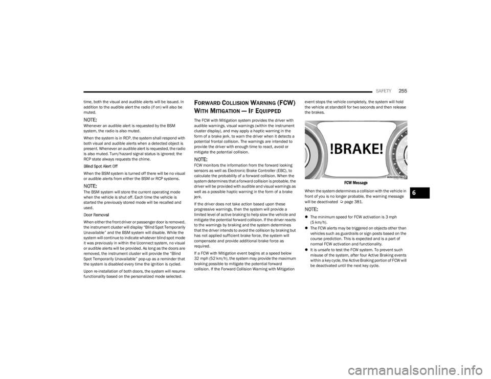
FORWARD COLLISION WARNING (FCW)
W
ITH MITIGATION — IF EQUIPPED
The FCW with Mitigation system provides the driver with
audible warnings, visual warnings (within the instrument
cluster display), and may apply a haptic warning in the
form of a brake jerk, to warn the driver when it detects a
potential frontal collision. The warnings are intended to
provide the driver with enough time to react, avoid or
mitigate the potential collision.
NOTE:FCW monitors the information from the forward looking
sensors as well as Electronic Brake Controller (EBC), to
calculate the probability of a forward collision. When the
system determines that a forward collision is probable, the
driver will be provided with audible and visual warnings as
well as a possible haptic warning in the form of a brake
jerk.
If the driver does not take action based upon these
progressive warnings, then the system will provide a
limited level of active braking to help slow the vehicle and
mitigate the potential forward collision. If the driver reacts
to the warnings by braking and the system determines
that the driver intends to avoid the collision by braking but
has not applied sufficient brake force, the system will
compensate and provide additional brake force as
required.
If a FCW with Mitigation event begins at a speed below
32 mph (52 km/h), the system may provide the maximum
braking possible to mitigate the potential forward
collision. If the Forward Collision Warning with Mitigation event stops the vehicle completely, the system will hold
the vehicle at standstill for two seconds and then release
the brakes.
FCW Message
When the system determines a collision with the vehicle in
front of you is no longer probable, the warning message
will be deactivated
Úpage 381.
NOTE:
The minimum speed for FCW activation is 3 mph
(5 km/h).
The FCW alerts may be triggered on objects other than
vehicles such as guardrails or sign posts based on the
course prediction. This is expected and is a part of
normal FCW activation and functionality.
It is unsafe to test the FCW system. To prevent such
misuse of the system, after four Active Braking events
within a key cycle, the Active Braking portion of FCW will
be deactivated until the next key cycle.
6
23_JL_OM_EN_USC_t.book Page 255
Page 262 of 396
260SAFETY
The system will be activated when the system detects an
increase in tire pressure while filling the tire. The ignition
must be in the ON/RUN mode with the transmission in
PARK for vehicles equipped with an automatic
transmission. For vehicles equipped with a manual
transmission, the parking brake must be applied.
NOTE:It is not required to have the engine running to enter Tire
Fill Alert mode.
The hazard lamps will come on to confirm the vehicle is in
Tire Fill Alert mode. If the hazard lamps do not come on
while inflating the tire, the Tire Pressure Monitoring
System sensor may be in an inoperative position,
preventing the TPMS sensor signal from being received. In
this case, the vehicle may need to be moved slightly
forward or backward.
When Tire Fill Alert mode is entered, the tire pressure
display screen will be displayed in the instrument cluster.
Operation:
The horn will chirp once to let the user know when to
stop filling the tire, when it reaches recommended
pressure.
The horn will chirp three times if the tire is overfilled
and will continue to chirp every five seconds if the user
continues to inflate the tire.
The horn will chirp once again when enough air is let
out to reach proper inflation level.
The horn will also chirp three times if the tire is then
underinflated and will continue to chirp every five
seconds if the user continues to deflate the tire.
NOTE:The Tire Fill Alert feature is set to “Disabled” every time the
ignition is turned to “OFF”. To re-enable the Tire Fill Alert
feature at the next ignition “RUN” state, the customer
must re-enable the feature through use of the customer
settings in the radio.
SELECTABLE TIRE FILL ALERT (STFA) —
IF EQUIPPED
The STFA system is an optional feature that is included as
part of the normal Tire Fill Alert system. The system is
designed to allow you to select a pressure to inflate or
deflate the vehicle's front and rear axle tires to, and to
provide feedback while inflating or deflating the vehicle's
tires.
NOTE:To use the STFA feature, the Tire Fill Alert feature must be
enabled through use of the customer settings in the radio.
In the Selectable Tire Fill Alert application, which is located
in the apps menu of the Uconnect system, you will be able
to select a pressure setting for both the front and rear axle
tire pressures by scrolling through a pressure range from
XX to 15 psi in 1 psi increments for each axle setting.
XX = the vehicle's cold placard pressure values for the
front and rear axles as shown on the vehicle placard
pressure label.
You may also store pressure values chosen for each axle
in the Uconnect system application as preset pressure
values. Up to two sets of preset pressure values can be
stored in the Uconnect system for the front and rear axle. Once you select the tire pressures for the front and rear
axles that you want to inflate or deflate to, you can begin
inflating or deflating one tire at a time.
NOTE:The STFA system will only support inflating or deflating one
tire at a time.
The system will be activated when the TPMS receiver
module detects a change in tire pressure. The ignition
must be in the ON/RUN mode, with the transmission in
PARK in vehicles with an automatic transmission, and in
NEUTRAL with the parking brake engaged in vehicles with
a manual transmission. The hazard lamps will come on to
confirm the vehicle is in Tire Fill Alert mode.
When Tire Fill Alert mode is entered, the tire pressure
screen will be displayed in the instrument cluster. If the
hazard lamps do not come on while inflating or deflating
the tire, the Tire Pressure Monitoring System sensor may
be in an inoperative position, preventing the TPMS sensor
signal from being received. In this case, the vehicle may
need to be moved slightly forward or backward.
Horn chirps will indicate STFA status as tires are inflated/
deflated. The horn will chirp under the following STFA
states:
1. The horn will chirp once when the selected pressure
is reached to let you know when to stop inflating or
deflating the tire.
2. The horn will chirp three times if the tire is overin -
flated or over-deflated.
3. The horn will chirp once again when enough air is added or removed to reach proper selected pressure
level.
23_JL_OM_EN_USC_t.book Page 260
Page 342 of 396
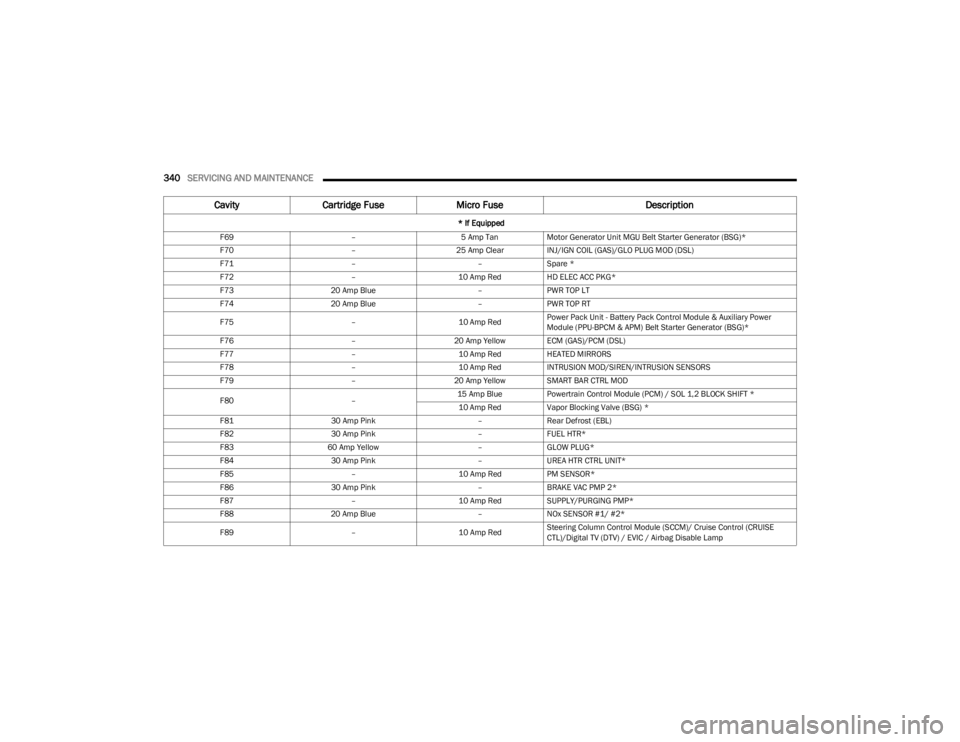
340SERVICING AND MAINTENANCE
F69 –5 Amp TanMotor Generator Unit MGU Belt Starter Generator (BSG)*
F70 –25 Amp ClearINJ/IGN COIL (GAS)/GLO PLUG MOD (DSL)
F71 ––Spare *
F72 –10 Amp RedHD ELEC ACC PKG*
F73 20 Amp Blue –PWR TOP LT
F74 20 Amp Blue –PWR TOP RT
F75 –10 Amp RedPower Pack Unit - Battery Pack Control Module & Auxiliary Power
Module (PPU-BPCM & APM) Belt Starter Generator (BSG)*
F76 –20 Amp Yellow ECM (GAS)/PCM (DSL)
F77 –10 Amp RedHEATED MIRRORS
F78 –10 Amp RedINTRUSION MOD/SIREN/INTRUSION SENSORS
F79 –20 Amp Yellow SMART BAR CTRL MOD
F80 –15 Amp Blue
Powertrain Control Module (PCM) / SOL 1,2 BLOCK SHIFT *
10 Amp Red Vapor Blocking Valve (BSG) *
F81 30 Amp Pink –Rear Defrost (EBL)
F82 30 Amp Pink –FUEL HTR*
F83 60 Amp Yellow –GLOW PLUG*
F84 30 Amp Pink –UREA HTR CTRL UNIT*
F85 –10 Amp RedPM SENSOR*
F86 30 Amp Pink –BRAKE VAC PMP 2*
F87 –10 Amp RedSUPPLY/PURGING PMP*
F88 20 Amp Blue –NOx SENSOR #1/ #2*
F89 –10 Amp RedSteering Column Control Module (SCCM)/ Cruise Control (CRUISE
CTL)/Digital TV (DTV) / EVIC / Airbag Disable Lamp
Cavity
Cartridge Fuse Micro Fuse Description
* If Equipped
23_JL_OM_EN_USC_t.book Page 340