hood open JEEP WRANGLER 2023 Owners Manual
[x] Cancel search | Manufacturer: JEEP, Model Year: 2023, Model line: WRANGLER, Model: JEEP WRANGLER 2023Pages: 396, PDF Size: 25.15 MB
Page 5 of 396
3
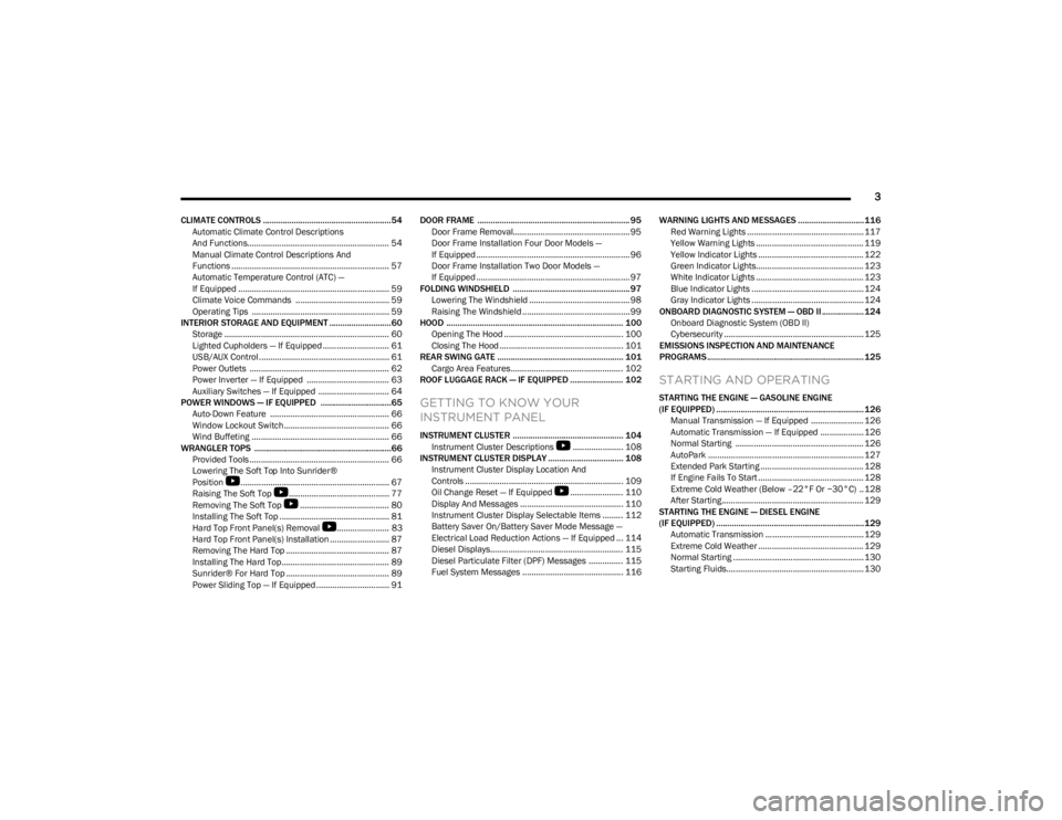
CLIMATE CONTROLS ..........................................................54Automatic Climate Control Descriptions
And Functions.............................................................. 54
Manual Climate Control Descriptions And
Functions ..................................................................... 57
Automatic Temperature Control (ATC) —
If Equipped .................................................................. 59
Climate Voice Commands ......................................... 59
Operating Tips ............................................................ 59
INTERIOR STORAGE AND EQUIPMENT ............................60 Storage ........................................................................ 60
Lighted Cupholders — If Equipped ............................. 61
USB/AUX Control ......................................................... 61
Power Outlets ............................................................. 62
Power Inverter — If Equipped .................................... 63
Auxiliary Switches — If Equipped ............................... 64
POWER WINDOWS — IF EQUIPPED ................................65 Auto-Down Feature .................................................... 66
Window Lockout Switch.............................................. 66
Wind Buffeting ............................................................ 66
WRANGLER TOPS ..............................................................66 Provided Tools ............................................................. 66
Lowering The Soft Top Into Sunrider®
Position
S
................................................................. 67
Raising The Soft Top
S
............................................ 77
Removing The Soft Top
S
....................................... 80
Installing The Soft Top ................................................ 81
Hard Top Front Panel(s) Removal
S
....................... 83
Hard Top Front Panel(s) Installation .......................... 87
Removing The Hard Top ............................................. 87
Installing The Hard Top............................................... 89
Sunrider® For Hard Top ............................................. 89
Power Sliding Top — If Equipped ................................ 91 DOOR FRAME ..................................................................... 95
Door Frame Removal................................................... 95
Door Frame Installation Four Door Models —
If Equipped ................................................................... 96
Door Frame Installation Two Door Models —
If Equipped ................................................................... 97
FOLDING WINDSHIELD ..................................................... 97 Lowering The Windshield ............................................ 98
Raising The Windshield ............................................... 99
HOOD ................................................................................ 100 Opening The Hood .................................................... 100
Closing The Hood ...................................................... 101
REAR SWING GATE ......................................................... 101 Cargo Area Features................................................. 102
ROOF LUGGAGE RACK — IF EQUIPPED ........................ 102
GETTING TO KNOW YOUR
INSTRUMENT PANEL
INSTRUMENT CLUSTER .................................................. 104 Instrument Cluster Descriptions
S
...................... 108
INSTRUMENT CLUSTER DISPLAY .................................. 108 Instrument Cluster Display Location And
Controls ..................................................................... 109
Oil Change Reset — If Equipped
S
....................... 110
Display And Messages ............................................. 110
Instrument Cluster Display Selectable Items ......... 112
Battery Saver On/Battery Saver Mode Message —
Electrical Load Reduction Actions — If Equipped ... 114
Diesel Displays.......................................................... 115
Diesel Particulate Filter (DPF) Messages ............... 115 Fuel System Messages ............................................ 116 WARNING LIGHTS AND MESSAGES ..............................116
Red Warning Lights ................................................... 117
Yellow Warning Lights ............................................... 119Yellow Indicator Lights .............................................. 122Green Indicator Lights............................................... 123White Indicator Lights ............................................... 123Blue Indicator Lights ................................................. 124
Gray Indicator Lights ................................................. 124
ONBOARD DIAGNOSTIC SYSTEM — OBD II ................... 124 Onboard Diagnostic System (OBD II)
Cybersecurity ............................................................. 125
EMISSIONS INSPECTION AND MAINTENANCE
PROGRAMS ....................................................................... 125
STARTING AND OPERATING
STARTING THE ENGINE — GASOLINE ENGINE
(IF EQUIPPED) ...................................................................126 Manual Transmission — If Equipped ....................... 126
Automatic Transmission — If Equipped ................... 126
Normal Starting ........................................................ 126
AutoPark .................................................................... 127Extended Park Starting ............................................. 128If Engine Fails To Start .............................................. 128Extreme Cold Weather (Below –22°F Or −30°C) .. 128
After Starting.............................................................. 129
STARTING THE ENGINE — DIESEL ENGINE
(IF EQUIPPED) ...................................................................129 Automatic Transmission ........................................... 129
Extreme Cold Weather .............................................. 129Normal Starting ......................................................... 130
Starting Fluids............................................................ 130
23_JL_OM_EN_USC_t.book Page 3
Page 11 of 396
9
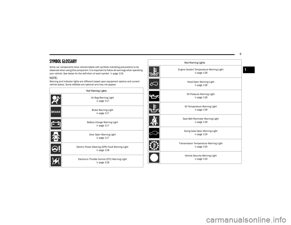
SYMBOL GLOSSARY
Some car components have colored labels with symbols indicating precautions to be
observed when using this component. It is important to follow all warnings when operating
your vehicle. See below for the definition of each symbol
Úpage 116.
NOTE:Warning and Indicator lights are different based upon equipment options and current
vehicle status. Some telltales are optional and may not appear.Red Warning Lights
Air Bag Warning Light
Úpage 117
Brake Warning Light
Úpage 117
Battery Charge Warning Light
Úpage 117
Door Open Warning Light
Úpage 117
Electric Power Steering (EPS) Fault Warning Light
Úpage 118
Electronic Throttle Control (ETC) Warning Light
Úpage 118
Engine Coolant Temperature Warning Light Úpage 118
Hood Open Warning Light
Úpage 118
Oil Pressure Warning Light
Úpage 118
Oil Temperature Warning Light
Úpage 118
Seat Belt Reminder Warning Light
Úpage 118
Swing Gate Open Warning Light
Úpage 119
Transmission Temperature Warning Light
Úpage 119
Vehicle Security Warning Light
Úpage 119
Red Warning Lights
1
23_JL_OM_EN_USC_t.book Page 9
Page 19 of 396
GETTING TO KNOW YOUR VEHICLE17
NOTE:
For more information on normal starting, see Úpage 126.
When opening the driver's door with the ignition in the
ON/RUN position (engine not running), a chime will
sound to remind you to place the ignition in the OFF
position. In addition to the chime, the message will
display “Ignition Or Accessory On” in the cluster.
REMOTE START — IF EQUIPPED
(GASOLINE)
If applicable, refer to the “Hybrid Supplement” for
additional information.
This system uses the key fob to start the engine
conveniently from outside the vehicle while still
maintaining security. The system has a range
of 328 ft (100 m).
Remote Start is used to defrost windows in cold weather,
and to reach a comfortable climate in all ambient
conditions before the driver enters the vehicle.
NOTE:
The vehicle must be equipped with an automatic trans -
mission to be equipped with Remote Start.
Obstructions between the vehicle and key fob may
reduce this range
Úpage 381.
HOW TO USE REMOTE START
Push and release the Remote Start button on the key fob
twice within five seconds. The vehicle doors and swing
gate will lock, the turn signals will flash twice, and the horn
will chirp twice. Pushing the Remote Start button again will
shut the engine off.
NOTE:
With Remote Start, the engine will only run for
15 minutes.
Remote Start can only be used twice.
If an engine fault is present or fuel level is low, the
vehicle will start and then shut down in 10 seconds.
The park lamps will turn on and remain on during
Remote Start mode.
For security, power window operation is disabled when
the vehicle is in the Remote Start mode.
The ignition must be placed in the ON/RUN position
before the Remote Start sequence can be repeated for
a third cycle.
All of the following conditions must be met before the
engine will remote start:
Gear selector in PARK
Doors closed
Hood closed
Swing gate closed
Hazard switch off
Brake switch inactive (brake pedal not pressed)
Battery at an acceptable charge level
Panic button not pushed
System not disabled from previous Remote Start event
Vehicle Security system indicator flashing
Ignition in OFF position
Fuel level meets minimum requirement
All removable doors must not be removed
Malfunction Indicator Light (MIL) not illuminated
CAUTION!
An unlocked vehicle is an invitation for thieves. Always
remove key fob from the vehicle and lock all doors
when leaving the vehicle unattended.
WARNING!
Do not start or run an engine in a closed garage or
confined area. Exhaust gas contains carbon
monoxide (CO) which is odorless and colorless.
Carbon monoxide is poisonous and can cause
serious injury or death when inhaled.
Keep key fobs away from children. Operation of the
Remote Start system, windows, door locks or other
controls could cause serious injury or death.
2
23_JL_OM_EN_USC_t.book Page 17
Page 20 of 396
18GETTING TO KNOW YOUR VEHICLE
TO EXIT REMOTE START MODE
To drive the vehicle after starting the Remote Start
system, either push and release the unlock button on the
key fob to unlock the doors, or unlock the vehicle using
Keyless Enter ‘n Go™ — Passive Entry via the door
handles, and disarm the Vehicle Security system (if
equipped). Then, prior to the end of the 15 minute cycle,
push and release the START/STOP ignition button.
The Remote Start system will turn the engine off if the
Remote Start button on the key fob is pushed again, or if
the engine is allowed to run for the entire 15 minute cycle.
Once the ignition is placed in the ON/RUN position, the
climate controls will resume previously set operations
(temperature, blower control, etc.).
NOTE:
To avoid unintentional shutdowns, the system will
disable for two seconds after receiving a valid Remote
Start request.
For vehicles equipped with the Keyless Enter ‘n Go™ —
Passive Entry feature, the message “Remote Start
Active — Push Start Button” will display in the instru -
ment cluster display until you push the START/STOP
ignition button.
REMOTE START FRONT DEFROST
A
CTIVATION — IF EQUIPPED
When Remote Start is active, and the outside ambient
temperature is 40°F (4.5°C) or below, the system will
automatically activate front defrost for 15 minutes or less.
The time is dependent on the ambient temperature. Once
the timer expires, the system will automatically adjust the settings depending on ambient conditions. See “Remote
Start Comfort Systems — If Equipped” in the next section
for detailed operation.
REMOTE START COMFORT SYSTEMS —
I
F EQUIPPED
When Remote Start is activated, the front and rear defrost
will automatically turn on in cold weather. The heated
steering wheel and driver heated seat feature will turn on if
programmed in the Comfort menu screen within Uconnect
Settings
Ú
page 184. In warm weather, the driver vented
seat feature will automatically turn on when the Remote
Start is activated, if programmed in the Comfort menu
screen. The vehicle will adjust the climate control settings
depending on the outside ambient temperature.
Automatic Temperature Control (ATC) — If Equipped
The climate controls automatically adjust to an optimal
temperature and mode, dependent on the outside
ambient temperature. When the ignition is placed in the
ON/RUN position, the climate controls will resume their
previous settings.
Manual Temperature Control (MTC) — If Equipped
In ambient temperatures of 40°F (4.5°C) or below, the
climate settings will default to maximum heat, with
fresh air entering the cabin. If the front defrost timer
expires, the vehicle will enter Mix mode.
In ambient temperatures from 40°F (4.5°C) to 78°F
(26°C), the climate settings will be based on the last
settings selected by the driver.
In ambient temperatures of 78°F (26°C) or above, the
climate settings will default to MAX A/C, Bi-Level mode,
with Recirculation on. For more information on ATC, MTC, and climate control
settings, see
Úpage 54.
NOTE:These features will stay on through the duration of Remote
Start, or until the ignition is placed in the ON/RUN
position. The climate control settings will change, and exit
the automatic defaults, if manually adjusted by the driver
while the vehicle is in Remote Start mode. This includes
turning the climate controls off using the OFF button.
REMOTE START WINDSHIELD WIPER
D
E-ICER ACTIVATION — IF EQUIPPED
When Remote Start is active and the outside ambient
temperature is less than 33°F (0.6°C), the Windshield
Wiper De-Icer will activate. Exiting Remote Start will
resume its previous operation. If the Windshield Wiper
De-Icer was active, the timer and operation will continue.
REMOTE START CANCEL MESSAGE
One of the following messages will display in the
instrument cluster if the vehicle fails to remote start or
exits Remote Start prematurely:
Remote Start Canceled — Door Open
Remote Start Canceled — Hood Open
Remote Start Canceled — Fuel Low
Remote Start Canceled — Swing Gate Open
Remote Start Canceled — Time Expired
Remote Start Disabled — Start Vehicle To Reset
The message will stay active until the ignition is placed in
the ON/RUN position.
23_JL_OM_EN_USC_t.book Page 18
Page 67 of 396
GETTING TO KNOW YOUR VEHICLE65
Wire Color Chart
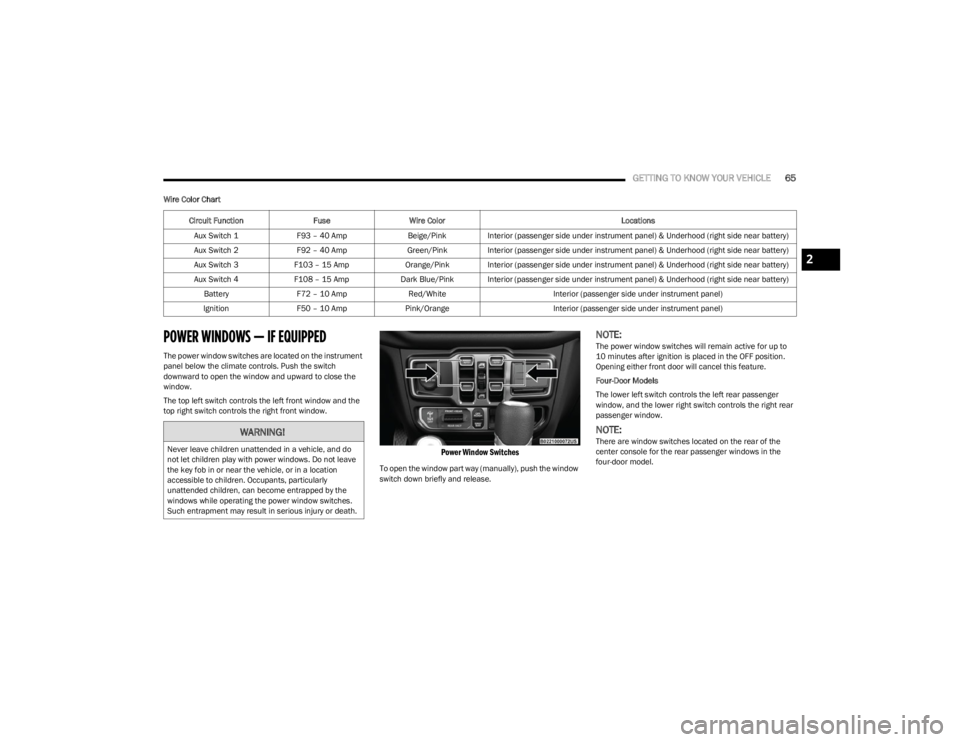
POWER WINDOWS — IF EQUIPPED
The power window switches are located on the instrument
panel below the climate controls. Push the switch
downward to open the window and upward to close the
window.
The top left switch controls the left front window and the
top right switch controls the right front window.
Power Window Switches
To open the window part way (manually), push the window
switch down briefly and release.
NOTE:The power window switches will remain active for up to
10 minutes after ignition is placed in the OFF position.
Opening either front door will cancel this feature.
Four-Door Models
The lower left switch controls the left rear passenger
window, and the lower right switch controls the right rear
passenger window.
NOTE:There are window switches located on the rear of the
center console for the rear passenger windows in the
four-door model.
Circuit Function
FuseWire Color Locations
Aux Switch 1 F93 – 40 Amp Beige/Pink Interior (passenger side under instrument panel) & Underhood (right side near battery)
Aux Switch 2 F92 – 40 Amp Green/Pink Interior (passenger side under instrument panel) & Underhood (right side near battery)
Aux Switch 3 F103 – 15 Amp Orange/Pink Interior (passenger side under instrument panel) & Underhood (right side near battery)
Aux Switch 4 F108 – 15 Amp Dark Blue/Pink Interior (passenger side under instrument panel) & Underhood (right side near battery)
Battery F72 – 10 Amp Red/White Interior (passenger side under instrument panel)
Ignition F50 – 10 Amp Pink/Orange Interior (passenger side under instrument panel)WARNING!
Never leave children unattended in a vehicle, and do
not let children play with power windows. Do not leave
the key fob in or near the vehicle, or in a location
accessible to children. Occupants, particularly
unattended children, can become entrapped by the
windows while operating the power window switches.
Such entrapment may result in serious injury or death.
2
23_JL_OM_EN_USC_t.book Page 65
Page 101 of 396
GETTING TO KNOW YOUR VEHICLE99
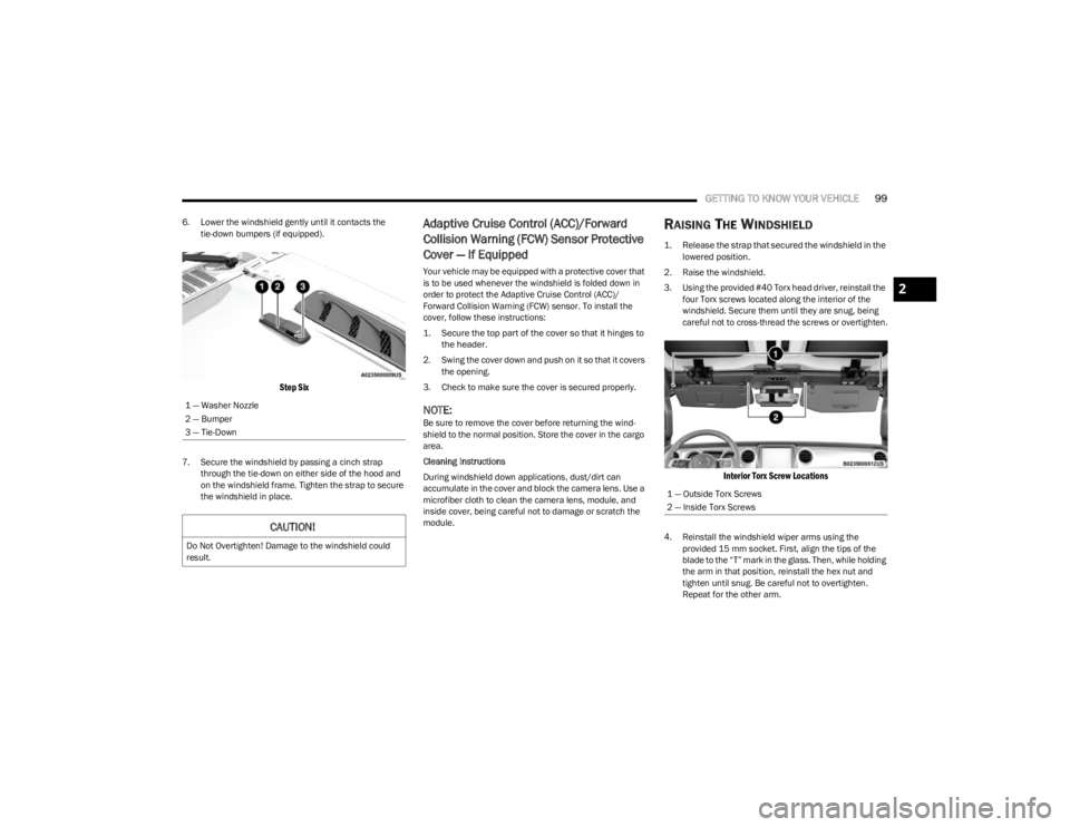
6. Lower the windshield gently until it contacts the
tie-down bumpers (if equipped).
Step Six
7. Secure the windshield by passing a cinch strap through the tie-down on either side of the hood and
on the windshield frame. Tighten the strap to secure
the windshield in place.
Adaptive Cruise Control (ACC)/Forward
Collision Warning (FCW) Sensor Protective
Cover — If Equipped
Your vehicle may be equipped with a protective cover that
is to be used whenever the windshield is folded down in
order to protect the Adaptive Cruise Control (ACC)/
Forward Collision Warning (FCW) sensor. To install the
cover, follow these instructions:
1. Secure the top part of the cover so that it hinges to the header.
2. Swing the cover down and push on it so that it covers the opening.
3. Check to make sure the cover is secured properly.
NOTE:Be sure to remove the cover before returning the wind -
shield to the normal position. Store the cover in the cargo
area.
Cleaning Instructions
During windshield down applications, dust/dirt can
accumulate in the cover and block the camera lens. Use a
microfiber cloth to clean the camera lens, module, and
inside cover, being careful not to damage or scratch the
module.
RAISING THE WINDSHIELD
1. Release the strap that secured the windshield in the lowered position.
2. Raise the windshield.
3. Using the provided #40 Torx head driver, reinstall the four Torx screws located along the interior of the
windshield. Secure them until they are snug, being
careful not to cross-thread the screws or overtighten.
Interior Torx Screw Locations
4. Reinstall the windshield wiper arms using the provided 15 mm socket. First, align the tips of the
blade to the “T” mark in the glass. Then, while holding
the arm in that position, reinstall the hex nut and
tighten until snug. Be careful not to overtighten.
Repeat for the other arm.
1 — Washer Nozzle
2 — Bumper
3 — Tie-DownCAUTION!
Do Not Overtighten! Damage to the windshield could
result.
1 — Outside Torx Screws
2 — Inside Torx Screws
2
23_JL_OM_EN_USC_t.book Page 99
Page 102 of 396
100GETTING TO KNOW YOUR VEHICLE
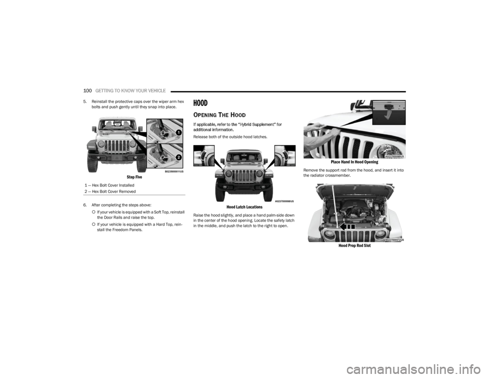
5. Reinstall the protective caps over the wiper arm hex
bolts and push gently until they snap into place.
Step Five
6. After completing the steps above:
If your vehicle is equipped with a Soft Top, reinstall
the Door Rails and raise the top.
If your vehicle is equipped with a Hard Top, rein -
stall the Freedom Panels.
HOOD
OPENING THE HOOD
If applicable, refer to the “Hybrid Supplement” for
additional information.
Release both of the outside hood latches.
Hood Latch Locations
Raise the hood slightly, and place a hand palm-side down
in the center of the hood opening. Locate the safety latch
in the middle, and push the latch to the right to open.
Place Hand In Hood Opening
Remove the support rod from the hood, and insert it into
the radiator crossmember.
Hood Prop Rod Slot
1 — Hex Bolt Cover Installed
2 — Hex Bolt Cover Removed
23_JL_OM_EN_USC_t.book Page 100
Page 103 of 396
GETTING TO KNOW YOUR VEHICLE101
NOTE:
Vehicle must be at a stop and the gear selector must
be in PARK.
You may have to push down slightly on the hood before
pushing the safety latch.
While lifting the hood, use both hands.
Before lifting the hood, check that the wiper arms are
not in motion and not in the lifted position.
CLOSING THE HOOD
If applicable, refer to the “Hybrid Supplement” for
additional information.
To close the hood, remove the support rod from the slot
and replace it on the hood panel retaining clip. Lower the
hood slowly. Secure both of the hood latches.
REAR SWING GATE
The rear swing gate can be unlocked by using one of the
following methods:
Mechanical key (with mechanical lock — if equipped)
Remote Keyless Entry key fob (if equipped)
Power door unlock switch on the front doors (if
equipped)
Passive Entry swing gate handle (if equipped)
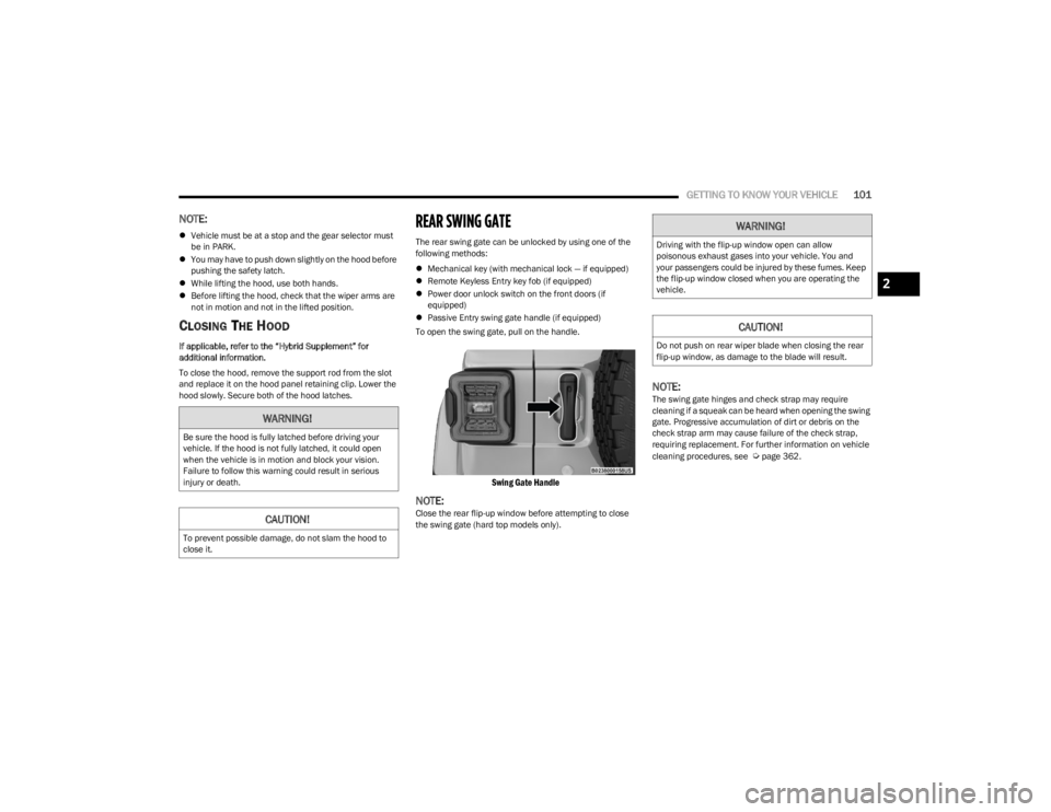
To open the swing gate, pull on the handle.
Swing Gate Handle
NOTE:Close the rear flip-up window before attempting to close
the swing gate (hard top models only).
NOTE:The swing gate hinges and check strap may require
cleaning if a squeak can be heard when opening the swing
gate. Progressive accumulation of dirt or debris on the
check strap arm may cause failure of the check strap,
requiring replacement. For further information on vehicle
cleaning procedures, see
Úpage 362.
WARNING!
Be sure the hood is fully latched before driving your
vehicle. If the hood is not fully latched, it could open
when the vehicle is in motion and block your vision.
Failure to follow this warning could result in serious
injury or death.
CAUTION!
To prevent possible damage, do not slam the hood to
close it.
WARNING!
Driving with the flip-up window open can allow
poisonous exhaust gases into your vehicle. You and
your passengers could be injured by these fumes. Keep
the flip-up window closed when you are operating the
vehicle.
CAUTION!
Do not push on rear wiper blade when closing the rear
flip-up window, as damage to the blade will result.
2
23_JL_OM_EN_USC_t.book Page 101
Page 113 of 396
GETTING TO KNOW YOUR INSTRUMENT PANEL111
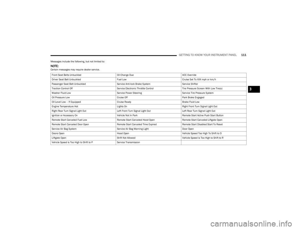
Messages include the following, but not limited to:
NOTE:Certain messages may require dealer service.
Front Seat Belts Unbuckled Oil Change DueACC Override
Driver Seat Belt Unbuckled Fuel LowCruise Set To XXX mph or km/h
Passenger Seat Belt Unbuckled Service Anti-lock Brake SystemService Shifter
Traction Control Off Service Electronic Throttle ControlTire Pressure Screen With Low Tire(s)
Washer Fluid Low Service Power SteeringService Tire Pressure System
Oil Pressure Low Cruise OffPark Brake Engaged
Oil Level Low – If Equipped Cruise ReadyBrake Fluid Low
Engine Temperature Hot Lights OnRight Front Turn Signal Light Out
Right Rear Turn Signal Light Out Left Front Turn Signal Light OutLeft Rear Turn Signal Light Out
Ignition or Accessory On Vehicle Not In ParkRemote Start Active Push Start Button
Remote Start Canceled Fuel Low Remote Start Canceled Hood OpenRemote Start Canceled Liftgate Open
Remote Start Canceled Door Open Remote Start Canceled Time ExpiredRemote Start Disabled Start To Reset
Service Air Bag System Service Air Bag Warning LightDoor Open
Doors Open Hood OpenVehicle Speed Too High To Shift to D
Liftgate Open Shift Not AllowedVehicle Speed is Too High to Shift to R
Vehicle Speed is Too High to Shift to P Service Transmission
3
23_JL_OM_EN_USC_t.book Page 111
Page 120 of 396
118GETTING TO KNOW YOUR INSTRUMENT PANEL
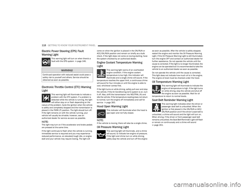
Electric Power Steering (EPS) Fault
Warning Light
This warning light will turn on when there's a
fault with the EPS system Úpage 146.
Electronic Throttle Control (ETC) Warning
Light
This warning light will illuminate to indicate a
problem with the ETC system. If a problem is
detected while the vehicle is running, the light
will either stay on or flash depending on the
nature of the problem. Cycle the ignition when the vehicle
is safely and completely stopped and the transmission is
placed in the PARK (P) position. The light should turn off.
If the light remains on with the vehicle running, your
vehicle will usually be drivable; however, see an
authorized dealer for service as soon as possible.
NOTE:This light may turn on if the accelerator and brake pedals
are pressed at the same time.
If the light continues to flash when the vehicle is running,
immediate service is required and you may experience
reduced performance, an elevated/rough idle, or engine
stall and your vehicle may require towing. The light will come on when the ignition is placed in the ON/RUN or
ACC/ON/RUN position and remain on briefly as a bulb
check. If the light does not come on during starting, have
the system checked by an authorized dealer.
Engine Coolant Temperature Warning
Light
This warning light warns of an overheated
engine condition. If the engine coolant
temperature is too high, this indicator will
illuminate and a single chime will sound. If the
temperature reaches the upper limit, a continuous chime
will sound for four minutes or until the engine is able to
cool, whichever comes first.
If the light turns on while driving, safely pull over and stop
the vehicle. If the Air Conditioning (A/C) system is on, turn
it off. Also, shift the transmission into NEUTRAL (N) and
idle the vehicle. If the temperature reading does not return
to normal, turn the engine off immediately and call for
service
Úpage 300.
Hood Open Warning Light
This indicator will illuminate when the hood is
ajar/open and not fully closed.
NOTE:If the vehicle is moving, there will also be a single chime.
Oil Pressure Warning Light
This warning light will illuminate, and a chime
will sound, to indicate low engine oil pressure.
If the light and chime turn on while driving,
safely stop the vehicle and turn off the engine as soon as possible. After the vehicle is safely stopped,
restart the engine and monitor the Oil Pressure Warning
Light. If the Oil Pressure Warning Light is still illuminated,
turn the engine OFF and contact an authorized dealer for
further assistance. Do not operate the vehicle until the
cause is corrected. If the light is no longer illuminated, the
engine can be operated but it is recommended to take the
vehicle to an authorized dealer as soon as possible.
Do not operate the vehicle until the cause is corrected.
This light does not indicate how much oil is in the engine.
The engine oil level must be checked under the hood.
Oil Temperature Warning Light
This warning light will illuminate to indicate the
engine oil temperature is high. If the light turns
on while driving, stop the vehicle and shut off
the engine as soon as possible. Wait for oil
temperature to return to normal levels.
Seat Belt Reminder Warning Light
This warning light indicates when the driver or
passenger seat belt is unbuckled. When the
ignition is first placed in the ON/RUN or ACC/
ON/RUN position and if the driver’s seat belt is
unbuckled, a chime will sound and the light will turn on.
When driving, if the driver or front passenger seat belt
remains unbuckled, the Seat Belt Reminder Light will flash
or remain on continuously and a chime will sound
Úpage 261.
WARNING!
Continued operation with reduced assist could pose a
safety risk to yourself and others. Service should be
obtained as soon as possible.
23_JL_OM_EN_USC_t.book Page 118