park assist JEEP WRANGLER 2023 Owners Manual
[x] Cancel search | Manufacturer: JEEP, Model Year: 2023, Model line: WRANGLER, Model: JEEP WRANGLER 2023Pages: 396, PDF Size: 25.15 MB
Page 6 of 396
4
NORMAL OPERATION — DIESEL ENGINE ..................... 130
Cold Weather Precautions........................................ 131Engine Idling .............................................................. 131Stopping The Engine ................................................. 132
Cooling System Tips — Automatic Transmission..... 132
ENGINE BREAK-IN RECOMMENDATIONS —
GASOLINE ENGINE (IF EQUIPPED) ................................ 133
ENGINE BREAK-IN RECOMMENDATIONS — DIESEL
ENGINE (IF EQUIPPED) .................................................... 133
PARKING BRAKE ............................................................. 133
MANUAL TRANSMISSION — IF EQUIPPED .................... 134 Shifting....................................................................... 135
Downshifting.............................................................. 136
AUTOMATIC TRANSMISSION — IF EQUIPPED .............. 137 Ignition Park Interlock............................................... 137Brake/Transmission Shift Interlock (BTSI)
System ...................................................................... 138
8–Speed Automatic Transmission .......................... 138
FOUR–WHEEL DRIVE OPERATION ............................... 140 Four-Position Transfer Case — If Equipped ............ 141Five-Position Transfer Case — If Equipped .............. 142
Trac-Lok Rear Axle — If Equipped ............................ 144
Axle Lock (Tru-Lok) Front And Rear — If Equipped ... 144
Axle Lock (Tru-Lok) Rear Only — If Equipped .......... 144
Electronic Sway Bar Disconnect — If Equipped ...... 145
Off Road+ — If Equipped........................................... 146
ELECTRO-HYDRAULIC POWER STEERING .................... 146
STOP/START SYSTEM — AUTOMATIC TRANSMISSION
(IF EQUIPPED) .................................................................. 147 Autostop Mode .......................................................... 147
Possible Reasons The Engine Does Not Autostop.. 148
To Start The Engine While In Autostop Mode.......... 148
To Manually Turn Off The Stop/Start System ......... 148
To Manually Turn On The Stop/Start System.......... 149
System Malfunction .................................................. 149 STOP/START SYSTEM — MANUAL TRANSMISSION
(IF EQUIPPED) .................................................................. 149
Autostop Mode.......................................................... 149
Possible Reasons The Engine Does Not
Autostop .................................................................... 150
To Start The Engine While In Autostop Mode ......... 150
To Manually Turn Off The Stop/Start System ......... 150
To Manually Turn On The Stop/Start System ......... 151
System Malfunction.................................................. 151
CRUISE CONTROL SYSTEMS — IF EQUIPPED ............. 151 Cruise Control ........................................................... 151
Adaptive Cruise Control (ACC).................................. 152
PARKSENSE REAR PARK ASSIST — IF EQUIPPED ...... 160 ParkSense Sensors .................................................. 160ParkSense Warning Display ..................................... 160
ParkSense Display.................................................... 160
Enabling And Disabling ParkSense ......................... 162
Service The ParkSense Rear Park Assist System... 162
Cleaning The ParkSense System ............................. 163ParkSense System Usage Precautions ................... 163
PARKVIEW REAR BACK UP CAMERA ........................... 163
TRAILCAM SYSTEM — IF EQUIPPED .............................. 164
REFUELING THE VEHICLE — GASOLINE ENGINE
(IF EQUIPPED) .................................................................. 165 Fuel Filler Cap ........................................................... 165
Loose Fuel Filler Cap Message ............................... 166
REFUELING THE VEHICLE — DIESEL ENGINE
(IF EQUIPPED) .................................................................. 166 Avoid Using Contaminated Fuel............................... 167
Bulk Fuel Storage — Diesel Fuel .............................. 167
Diesel Exhaust Fluid ................................................. 167
VEHICLE LOADING ........................................................... 169 Certification Label..................................................... 169 TRAILER TOWING ............................................................170
Common Towing Definitions..................................... 170
Trailer Hitch Classification ........................................ 172Trailer Towing Weights (Maximum Trailer Weight
Ratings) ..................................................................... 172
Trailer And Tongue Weight........................................ 173Towing Requirements ............................................... 173Towing Tips ................................................................ 175
RECREATIONAL TOWING (BEHIND MOTORHOME) ...... 176 Towing This Vehicle Behind Another Vehicle ........... 176Recreational Towing — Four-Wheel Drive Models ... 176
DRIVING TIPS ....................................................................178 On-Road Driving Tips ................................................. 178
Off-Road Driving Tips................................................. 178
MULTIMEDIA
UCONNECT SYSTEMS ......................................................184
CYBERSECURITY ..............................................................184
UCONNECT SETTINGS ......................................................184 Customer Programmable Features ......................... 184
UCONNECT INTRODUCTION ............................................ 197 System Overview ...................................................... 197Drag & Drop Menu Bar ............................................. 200Safety And General Information ............................... 200
UCONNECT MODES .......................................................... 201 Steering Wheel Audio Controls ................................ 201Radio Mode .............................................................. 201
Media Mode .............................................................. 210
Phone Mode ............................................................. 212
23_JL_OM_EN_USC_t.book Page 4
Page 7 of 396
5
ANDROID AUTO™ & APPLE CARPLAY® —
IF EQUIPPED ..................................................................... 222Android Auto™
S
.................................................... 222
Apple CarPlay®
S
.................................................. 224
Android Auto™ And Apple CarPlay® Tips And
Tricks.......................................................................... 225
CONNECTED VEHICLE SERVICES — IF EQUIPPED ...... 225 Is My Vehicle Connected? ........................................ 225Introduction To Connected Vehicle Services .......... 226
Getting Started With Connected Vehicle Services ... 227
Using SiriusXM Guardian™ ...................................... 228
Manage My SiriusXM Guardian™ Account ............. 237
CONNECTED SERVICES FAQS ....................................... 237 Connected Services SOS FAQs — If Equipped ........ 237
Connected Services Remote Door Lock/Unlock
FAQs .......................................................................... 237
Connected Services Roadside Assistance FAQs .... 237Connected Services Send & Go FAQs —
If Equipped ............................................................... 238
Connected Services Vehicle Finder FAQs ............... 238
Connected Services Stolen Vehicle Assistance
FAQs — If Equipped .................................................. 238
Connected Services Remote Vehicle Start FAQs ... 238
Connected Services Remote Horn & Lights FAQs .. 239
Connected Services Account FAQs — If Equipped .. 239
Data Collection & Privacy ......................................... 240
RADIO OPERATION AND MOBILE PHONES .................. 240 Regulatory And Safety Information .......................... 241
OFF-ROAD PAGES — IF EQUIPPED ................................ 241 Off-Road Pages Status Bar ...................................... 241
Drivetrain .................................................................. 242
Accessory Gauge ...................................................... 242Pitch & Roll ............................................................... 242
TrailCam — If Equipped ............................................. 243
SAFETY
SAFETY FEATURES .......................................................... 244 Anti-Lock Brake System (ABS) ................................ 244
Rear Seat Reminder Alert (RSRA) — If Equipped .... 244
Electronic Brake Control (EBC) System .................. 245
AUXILIARY DRIVING SYSTEMS ...................................... 252 Blind Spot Monitoring (BSM) — If Equipped ........... 252
Forward Collision Warning (FCW) With
Mitigation — If Equipped........................................... 255Tire Pressure Monitoring System (TPMS) ............... 257
OCCUPANT RESTRAINT SYSTEMS ............................... 261 Occupant Restraint Systems Features ................... 261
Important Safety Precautions .................................. 261
Seat Belt Systems .................................................... 261
Supplemental Restraint Systems (SRS).................. 267
Child Restraints ........................................................ 277
SAFETY TIPS ..................................................................... 288 Transporting Passengers ......................................... 288
Transporting Pets ..................................................... 288
Connected Vehicles .................................................. 288Safety Checks You Should Make Inside The
Vehicle ...................................................................... 288
Periodic Safety Checks You Should Make Outside
The Vehicle ................................................................ 290Exhaust Gas .............................................................. 290
Carbon Monoxide Warnings ..................................... 290
IN CASE OF EMERGENCY
HAZARD WARNING FLASHERS ..................................... 291
ASSIST AND SOS SYSTEM — IF EQUIPPED .................. 291 JACKING AND TIRE CHANGING
S
...............................293
Preparations For Jacking ......................................... 294
Jack Location ............................................................ 294 Spare Tire Removal .................................................. 295
Jacking Instructions .................................................. 295
JUMP STARTING ..............................................................298 Preparations For Jump Start..................................... 298
Jump Starting Procedure .......................................... 299
IF YOUR ENGINE OVERHEATS......................................... 300
MANUAL PARK RELEASE ................................................301
FREEING A STUCK VEHICLE ........................................... 302
TOWING A DISABLED VEHICLE.......................................303 Four–Wheel Drive Models ........................................ 303Without The Key Fob ................................................. 304
Emergency Tow Hooks — If Equipped ..................... 304
ENHANCED ACCIDENT RESPONSE SYSTEM (EARS) ..305
EVENT DATA RECORDER (EDR)......................................305
SERVICING AND MAINTENANCE
SCHEDULED SERVICING — GASOLINE ENGINE ...........306 Maintenance Plan ..................................................... 307
SCHEDULED SERVICING — DIESEL ENGINE .................310 Maintenance Plan — Diesel Fuel Up To B5
Biodiesel .................................................................... 311Additional Maintenance — B6 To B20 Biodiesel ..... 313
ENGINE COMPARTMENT ................................................. 314 2.0L Gasoline Engine ............................................... 3143.6L Gasoline Engine ............................................... 3153.0L Diesel Engine .................................................... 316
Checking Oil Level ..................................................... 317Adding Washer Fluid ................................................. 317
Maintenance-Free Battery ....................................... 317Pressure Washing ..................................................... 318
23_JL_OM_EN_USC_t.book Page 5
Page 52 of 396
50GETTING TO KNOW YOUR VEHICLE
TROUBLESHOOTING TIPS
If you are having trouble programming HomeLink®, here
are some of the most common solutions:
Replace the battery in the garage door opener
hand-held transmitter.
Push the LEARN button on the garage door opener to
complete the training for a rolling code.
Did you unplug the device for programming and
remember to plug it back in?
If you have any problems, or require assistance, please
call toll-free 1-800-355-3515 or, on the Internet at
HomeLink.com for information or assistance.
EXTERIOR LIGHTS
HEADLIGHT SWITCH
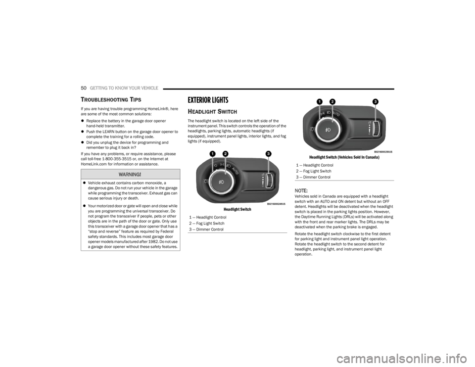
The headlight switch is located on the left side of the
instrument panel. This switch controls the operation of the
headlights, parking lights, automatic headlights (if
equipped), instrument panel lights, interior lights, and fog
lights (if equipped).
Headlight Switch Headlight Switch (Vehicles Sold In Canada)
NOTE:Vehicles sold in Canada are equipped with a headlight
switch with an AUTO and ON detent but without an OFF
detent. Headlights will be deactivated when the headlight
switch is placed in the parking lights position. However,
the Daytime Running Lights (DRLs) will be activated along
with the front and rear marker lights. The DRLs may be
deactivated when the parking brake is engaged.
Rotate the headlight switch clockwise to the first detent
for parking light and instrument panel light operation.
Rotate the headlight switch to the second detent for
headlight, parking light, and instrument panel light
operation.
WARNING!
Vehicle exhaust contains carbon monoxide, a
dangerous gas. Do not run your vehicle in the garage
while programming the transceiver. Exhaust gas can
cause serious injury or death.
Your motorized door or gate will open and close while
you are programming the universal transceiver. Do
not program the transceiver if people, pets or other
objects are in the path of the door or gate. Only use
this transceiver with a garage door opener that has a
“stop and reverse” feature as required by Federal
safety standards. This includes most garage door
opener models manufactured after 1982. Do not use
a garage door opener without these safety features.
1 — Headlight Control
2 — Fog Light Switch
3 — Dimmer Control
1 — Headlight Control
2 — Fog Light Switch
3 — Dimmer Control
23_JL_OM_EN_USC_t.book Page 50
Page 54 of 396
52GETTING TO KNOW YOUR VEHICLE
FRONT FOG LIGHTS — IF EQUIPPED
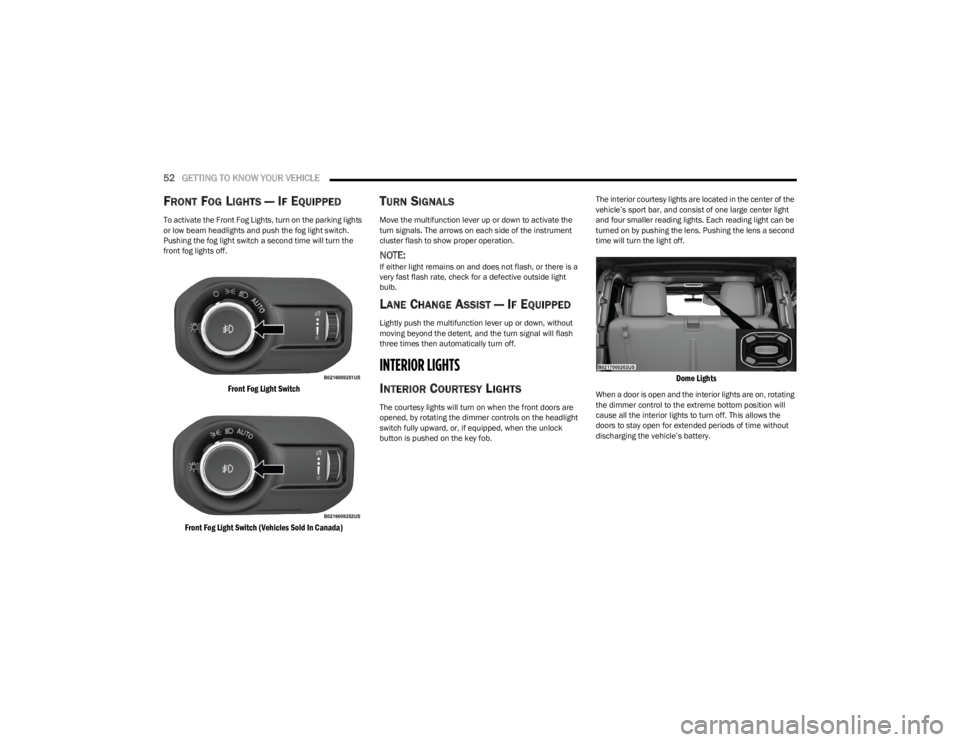
To activate the Front Fog Lights, turn on the parking lights
or low beam headlights and push the fog light switch.
Pushing the fog light switch a second time will turn the
front fog lights off.
Front Fog Light Switch
Front Fog Light Switch (Vehicles Sold In Canada)
TURN SIGNALS
Move the multifunction lever up or down to activate the
turn signals. The arrows on each side of the instrument
cluster flash to show proper operation.
NOTE:If either light remains on and does not flash, or there is a
very fast flash rate, check for a defective outside light
bulb.
LANE CHANGE ASSIST — IF EQUIPPED
Lightly push the multifunction lever up or down, without
moving beyond the detent, and the turn signal will flash
three times then automatically turn off.
INTERIOR LIGHTS
INTERIOR COURTESY LIGHTS
The courtesy lights will turn on when the front doors are
opened, by rotating the dimmer controls on the headlight
switch fully upward, or, if equipped, when the unlock
button is pushed on the key fob. The interior courtesy lights are located in the center of the
vehicle’s sport bar, and consist of one large center light
and four smaller reading lights. Each reading light can be
turned on by pushing the lens. Pushing the lens a second
time will turn the light off.
Dome Lights
When a door is open and the interior lights are on, rotating
the dimmer control to the extreme bottom position will
cause all the interior lights to turn off. This allows the
doors to stay open for extended periods of time without
discharging the vehicle’s battery.
23_JL_OM_EN_USC_t.book Page 52
Page 118 of 396
116GETTING TO KNOW YOUR INSTRUMENT PANEL
Your vehicle has the ability to alert you to additional
maintenance required on your vehicle or engine. Refer to
the following messages that may be displayed on your
instrument cluster display:
Exhaust Filter Nearing Full Safely Drive at Consistent
Speeds to Clear — This message will be displayed if the
exhaust particulate filter reaches 80% of its maximum
storage capacity. Under conditions of exclusive short
duration and low speed driving cycles, your diesel
engine and exhaust after-treatment system may never
reach the conditions required to cleanse the filter to
remove the trapped PM. If this occurs, the “Exhaust Filter XX% Full Safely Drive at Highway Speeds to
Remedy” message will be displayed. If this message is
displayed, you will hear one chime to assist in alerting
you of this condition. By simply driving your vehicle at
highway speeds for up to 20 minutes, you can remedy
the condition in the particulate filter system and allow
your diesel engine and exhaust after-treatment system
to cleanse the filter to remove the trapped PM and
restore the system to normal operating condition.
Exhaust System Regeneration in Process Continue
Driving — This message indicates that the DPF is
self-cleaning. Maintain your current driving condition
until regeneration is completed.
Exhaust System — Regeneration Completed — This
message indicates that the DPF self-cleaning is
completed. If this message is displayed, you will hear
one chime to assist in alerting you of this condition.
Exhaust System Service Required — See Dealer — This
messages indicates regeneration has been disabled
due to a system malfunction. At this point the engine
Powertrain Control Module (PCM) will register a fault
code, the instrument panel will display a Malfunction
Indicator Light (MIL).
Exhaust Filter Full — Power Reduced See Dealer — This
message indicates the PCM has derated the engine to
limit the likelihood of permanent damage to the
after-treatment system. If this condition is not
corrected and a dealer service is not performed, exten -sive exhaust after-treatment damage can occur. To
correct this condition it will be necessary to have your
vehicle serviced by an authorized dealer.
NOTE:Failing to follow the oil change indicator, changing your oil
and resetting the oil change indicator by 0 miles (0 kilo
-
meters) remaining will prevent the diesel exhaust filter
from performing its cleaning routine. This will shortly result
in a Malfunction Indicator Light (MIL) and reduced engine
power. Only an authorized dealer will be able to correct
this condition.
FUEL SYSTEM MESSAGES
The following chart contains a list of different messages
that may appear in the instrument cluster, depending on
different system or fuel conditions. Use the descriptions to
interpret what the message means and determine the
best action to take.
WARNING LIGHTS AND MESSAGES
The warning/indicator lights will illuminate in the
instrument panel together with a dedicated message and/
or acoustic signal when applicable. These indications are
indicative and precautionary and as such must not be
considered as exhaustive and/or alternative to the
information contained in the Owner’s Manual, which you
are advised to read carefully in all cases. Always refer to
WARNING!
A malfunctioning catalytic converter, as previously
referenced, can reach higher temperatures than in
normal operating conditions. This can cause a fire if you
drive slowly or park over flammable substances such as
dry plants, wood, cardboard, etc. This could result in
death or serious injury to the driver, occupants or
others.
CAUTION!
The engine may be switched off even if the warning
light is on: repeated interruptions of the regeneration
process could cause an early deterioration of engine oil.
For this reason it is always advisable to wait for the
symbol to go off before turning off the engine, following
the previously mentioned instructions. Do not complete
the DPF regeneration process when the vehicle is
stopped.
CAUTION!
See an authorized dealer, as damage to the exhaust
system could occur soon with continued operation.
CAUTION!
See an authorized dealer, as damage to the exhaust
system could occur soon with continued operation.
23_JL_OM_EN_USC_t.book Page 116
Page 120 of 396
118GETTING TO KNOW YOUR INSTRUMENT PANEL
Electric Power Steering (EPS) Fault
Warning Light
This warning light will turn on when there's a
fault with the EPS system Úpage 146.
Electronic Throttle Control (ETC) Warning
Light
This warning light will illuminate to indicate a
problem with the ETC system. If a problem is
detected while the vehicle is running, the light
will either stay on or flash depending on the
nature of the problem. Cycle the ignition when the vehicle
is safely and completely stopped and the transmission is
placed in the PARK (P) position. The light should turn off.
If the light remains on with the vehicle running, your
vehicle will usually be drivable; however, see an
authorized dealer for service as soon as possible.
NOTE:This light may turn on if the accelerator and brake pedals
are pressed at the same time.
If the light continues to flash when the vehicle is running,
immediate service is required and you may experience
reduced performance, an elevated/rough idle, or engine
stall and your vehicle may require towing. The light will come on when the ignition is placed in the ON/RUN or
ACC/ON/RUN position and remain on briefly as a bulb
check. If the light does not come on during starting, have
the system checked by an authorized dealer.
Engine Coolant Temperature Warning
Light
This warning light warns of an overheated
engine condition. If the engine coolant
temperature is too high, this indicator will
illuminate and a single chime will sound. If the
temperature reaches the upper limit, a continuous chime
will sound for four minutes or until the engine is able to
cool, whichever comes first.
If the light turns on while driving, safely pull over and stop
the vehicle. If the Air Conditioning (A/C) system is on, turn
it off. Also, shift the transmission into NEUTRAL (N) and
idle the vehicle. If the temperature reading does not return
to normal, turn the engine off immediately and call for
service
Úpage 300.
Hood Open Warning Light
This indicator will illuminate when the hood is
ajar/open and not fully closed.
NOTE:If the vehicle is moving, there will also be a single chime.
Oil Pressure Warning Light
This warning light will illuminate, and a chime
will sound, to indicate low engine oil pressure.
If the light and chime turn on while driving,
safely stop the vehicle and turn off the engine as soon as possible. After the vehicle is safely stopped,
restart the engine and monitor the Oil Pressure Warning
Light. If the Oil Pressure Warning Light is still illuminated,
turn the engine OFF and contact an authorized dealer for
further assistance. Do not operate the vehicle until the
cause is corrected. If the light is no longer illuminated, the
engine can be operated but it is recommended to take the
vehicle to an authorized dealer as soon as possible.
Do not operate the vehicle until the cause is corrected.
This light does not indicate how much oil is in the engine.
The engine oil level must be checked under the hood.
Oil Temperature Warning Light
This warning light will illuminate to indicate the
engine oil temperature is high. If the light turns
on while driving, stop the vehicle and shut off
the engine as soon as possible. Wait for oil
temperature to return to normal levels.
Seat Belt Reminder Warning Light
This warning light indicates when the driver or
passenger seat belt is unbuckled. When the
ignition is first placed in the ON/RUN or ACC/
ON/RUN position and if the driver’s seat belt is
unbuckled, a chime will sound and the light will turn on.
When driving, if the driver or front passenger seat belt
remains unbuckled, the Seat Belt Reminder Light will flash
or remain on continuously and a chime will sound
Úpage 261.
WARNING!
Continued operation with reduced assist could pose a
safety risk to yourself and others. Service should be
obtained as soon as possible.
23_JL_OM_EN_USC_t.book Page 118
Page 129 of 396
STARTING AND OPERATING127
seconds (or three short pushes in a row) to turn the
engine off. The ignition will remain in the ACC position
(NOT the OFF position) if the engine is turned off when
the transmission is not in PARK.
NOTE:The system will automatically time out and the ignition will
cycle to the OFF position after 30 minutes of inactivity if
the ignition is left in the ACC or RUN (engine not running)
position and the transmission is in PARK.
ENGINE START/STOP Button Functions — With Driver’s
Foot OFF The Brake Pedal (In PARK Or NEUTRAL Position)
The ENGINE START/STOP button operates similar to an
ignition switch. It has three positions: OFF, ACC, and RUN.
To change the ignition positions without starting the
vehicle and use the accessories, follow these steps:
1. Start with the ignition in the OFF position.
2. Push the ENGINE START/STOP button once to place
the ignition to the ACC position (instrument cluster
will display “ACC”).
3. Push the ENGINE START/STOP button a second time to place the ignition to the RUN position (instrument
cluster will display “ON/RUN”).
4. Push the ENGINE START/STOP button a third time to return the ignition to the OFF position (instrument
cluster will display “OFF”).
AUTOPARK
AutoPark is a supplemental feature to assist with placing
the vehicle in PARK should the situations on the following
pages occur. It is a back-up system and should not be relied upon as the primary method by which the driver
shifts the vehicle into PARK.
The conditions under which AutoPark will engage are
outlined on the following pages.
If the vehicle is not in PARK and the driver turns off the
engine, the vehicle may AutoPark.
AutoPark will engage when all of these conditions are met:
Vehicle is equipped with an 8-speed transmission
Driver’s door is ajar or if the driver’s door is removed
and the driver is not on the seat (seat pad sensor
detects driver missing)
Vehicle is not in PARK
Vehicle speed is 1.2 mph (1.9 km/h) or less
Ignition is switched from RUN to OFF
NOTE:For Keyless Enter ‘n Go™ equipped vehicles, the engine
will turn off and the ignition switch will change to ACC
position.
If the vehicle is not in PARK and the driver exits the vehicle
with the engine running, the vehicle may AutoPark.
AutoPark will engage when all of these conditions are met:
Vehicle is equipped with an 8-speed transmission
Driver’s door is ajar or if the driver’s door is removed
and the driver is not on the seat (seat pad sensor
detects driver missing)
Vehicle is not in PARK
Vehicle speed is 1.2 mph (1.9 km/h) or less
Driver’s seat belt is unbuckled
Brake pedal is not pressed
The message “ AutoPark Engaged Shift To P Then Shift To
Gear ” will display in the instrument cluster.
NOTE:In some cases the ParkSense graphic will be displayed in
the instrument cluster. In these cases, the gear selector
must be returned to “P” to select desired gear.
If the driver shifts into PARK while moving, the vehicle may
AutoPark.
AutoPark will engage ONLY when vehicle speed is 1.2 mph
(1.9 km/h) or less.
The message “ Vehicle Speed Is Too High To Shift To P ” will
be displayed in the instrument cluster if vehicle speed is
above 1.2 mph (1.9 km/h).
WARNING!
Driver inattention could lead to failure to place the
vehicle in PARK. ALWAYS DO A VISUAL CHECK that
your vehicle is in PARK by verifying that a solid (not
blinking) “P” is indicated in the instrument cluster
display and on the gear selector. If the "P" indicator is
blinking, your vehicle is not in PARK. As an added
precaution, always apply the parking brake when
exiting the vehicle.
AutoPark is a supplemental feature. It is not
designed to replace the need to shift your vehicle
into PARK. It is a back-up system and should not be
relied upon as the primary method by which the
driver shifts the vehicle into PARK.
4
23_JL_OM_EN_USC_t.book Page 127
Page 149 of 396
STARTING AND OPERATING147
If the “SERVICE POWER STEERING” message and a
flashing icon are displayed on the instrument cluster
screen, it indicates that the vehicle needs to be taken to
an authorized dealer for service. It is likely the vehicle has
lost power steering assistance
Úpage 108.
If the “POWER STEERING HOT” message and an icon are
displayed on the instrument cluster screen, it indicates
that extreme steering maneuvers may have occurred,
which caused an over temperature condition in the power
steering system. You will lose power steering assistance
momentarily until the over temperature condition no
longer exists. Once driving conditions are safe, pull over
and let vehicle idle for a few moments until the light turns
off
Úpage 108.
NOTE:
Even if power steering assistance is no longer opera -
tional, it is still possible to steer the vehicle. Under
these conditions there will be a substantial increase in
steering effort, especially at very low vehicle speeds
and during parking maneuvers.
If the condition persists, see an authorized dealer for
service.
STOP/START SYSTEM — AUTOMATIC
TRANSMISSION (IF EQUIPPED)
The Engine Stop/Start (ESS) function is designed to
reduce fuel consumption. The system will stop the engine
automatically during a vehicle stop if the required
conditions are met. Releasing the brake pedal or pressing
the accelerator pedal will automatically restart the engine. ESS vehicles have been upgraded with a heavy-duty
starter, enhanced battery, and other upgraded engine
parts, to handle the additional engine starts. Vehicles
equipped with eTorque contain a heavy-duty motor
generator and an additional hybrid electric battery to store
energy from vehicle deceleration for use on engine startup
after a stop as well as providing launch torque assist.
NOTE:It is recommended that Stop/Start system be disabled
during off-road use.
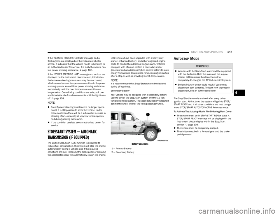
Secondary Battery
Your vehicle may be equipped with a secondary battery
used to power the Stop/Start system and the 12 Volt
vehicle electrical system. The secondary battery is located
behind the wheel well for the front passenger wheel.
Battery Locations
AUTOSTOP MODE
The Stop/Start feature is enabled after every driver
ignition start. At that time, the system will go into STOP/
START READY and if all other conditions are met, can go
into a STOP/START AUTOSTOP ACTIVE Autostop mode.
To Activate The Autostop Mode, The Following Must Occur:
The system must be in STOP/START READY state. A
STOP/START READY message will be displayed in the
instrument cluster display within the Stop/Start
section
Úpage 108.
The vehicle must be completely stopped.
The shifter must be in a forward gear and the brake
pedal pressed.
1 — Primary Battery
2 — Secondary Battery
WARNING!
Vehicles with the Stop/Start system will be equipped
with two batteries. Both the main and the supple -
mental batteries must be disconnected to
completely de-energize the 12 Volt electrical system.
Serious injury or death could result if you do not
disconnect both batteries. To learn how to properly
disconnect, see an authorized dealer.
4
23_JL_OM_EN_USC_t.book Page 147
Page 162 of 396
160STARTING AND OPERATING
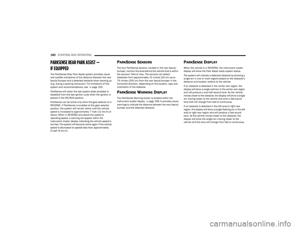
PARKSENSE REAR PARK ASSIST —
IF EQUIPPED
The ParkSense Rear Park Assist system provides visual
and audible indications of the distance between the rear
fascia/bumper and a detected obstacle when backing up
(e.g. during a parking maneuver). For limitations of this
system and recommendations, see
Úpage 163.
ParkSense will retain the last system state (enabled or
disabled) from the last ignition cycle when the ignition is
placed in the ON/RUN position.
ParkSense can be active only when the gear selector is in
REVERSE. If ParkSense is enabled at this gear selector
position, the system will remain active until the vehicle
speed is increased to approximately 7 mph (11 km/h) or
above. When in REVERSE and above the system's
operating speed, a warning will appear within the
instrument cluster display indicating the vehicle speed is
too fast. The system will become active again if the vehicle
speed is decreased to speeds less than approximately
6 mph (9 km/h).
PARKSENSE SENSORS
The four ParkSense sensors, located in the rear fascia/
bumper, monitor the area behind the vehicle that is within
the sensors’ field of view. The sensors can detect
obstacles from approximately 12 inches (30 cm) up to
79 inches (200 cm) from the rear fascia/bumper in the
horizontal direction, depending on the location, type and
orientation of the obstacle.
PARKSENSE WARNING DISPLAY
The ParkSense Warning screen is located within the
instrument cluster display Úpage 108. It provides visual
warnings to indicate the distance between the rear fascia/
bumper and the detected obstacle.
PARKSENSE DISPLAY
When the vehicle is in REVERSE, the instrument cluster
display will show the Park Assist ready system status.
The system will indicate a detected obstacle by showing a
single arc in one or more regions based on the obstacle’s
distance and location relative to the vehicle.
If an obstacle is detected in the center rear region, the
display will show a single solid arc in the center rear region
and will produce a one-half second tone. As the vehicle
moves closer to the obstacle, the display will show a single
arc moving closer to the vehicle and emit a fast sound
tone that will change from fast to continuous.
If an obstacle is detected in the left and/or right rear
region, the display will show a single flashing arc in the left
and/or right rear region and will produce a fast sound
tone. As the vehicle moves closer to the obstacle, the
display will show the single arc moving closer to the
vehicle and the tone will change from fast to continuous.
23_JL_OM_EN_USC_t.book Page 160
Page 164 of 396
162STARTING AND OPERATING
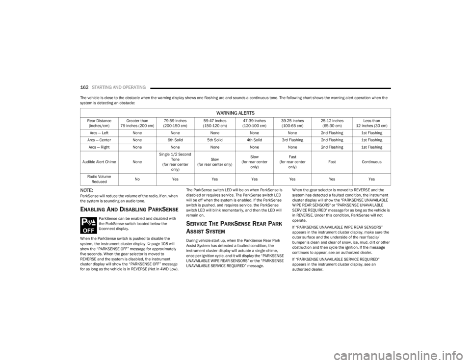
The vehicle is close to the obstacle when the warning display shows one flashing arc and sounds a continuous tone. The following chart shows the warning alert operation when the
system is detecting an obstacle:
NOTE:ParkSense will reduce the volume of the radio, if on, when
the system is sounding an audio tone.
ENABLING AND DISABLING PARKSENSE
ParkSense can be enabled and disabled with
the ParkSense switch located below the
Uconnect display.
When the ParkSense switch is pushed to disable the
system, the instrument cluster display
Úpage 108 will
show the “PARKSENSE OFF” message for approximately
five seconds. When the gear selector is moved to
REVERSE and the system is disabled, the instrument
cluster display will show the “PARKSENSE OFF” message
for as long as the vehicle is in REVERSE (Not in 4WD Low). The ParkSense switch LED will be on when ParkSense is
disabled or requires service. The ParkSense switch LED
will be off when the system is enabled. If the ParkSense
switch is pushed, and requires service, the ParkSense
switch LED will blink momentarily, and then the LED will
remain on.
SERVICE THE PARKSENSE REAR PARK
A
SSIST SYSTEM
During vehicle start up, when the ParkSense Rear Park
Assist System has detected a faulted condition, the
instrument cluster display will actuate a single chime,
once per ignition cycle, and it will display the “PARKSENSE
UNAVAILABLE WIPE REAR SENSORS” or the “PARKSENSE
UNAVAILABLE SERVICE REQUIRED” message. When the gear selector is moved to REVERSE and the
system has detected a faulted condition, the instrument
cluster display will show the "PARKSENSE UNAVAILABLE
WIPE REAR SENSORS" or "PARKSENSE UNAVAILABLE
SERVICE REQUIRED" message for as long as the vehicle is
in REVERSE. Under this condition, ParkSense will not
operate.
If “PARKSENSE UNAVAILABLE WIPE REAR SENSORS”
appears in the instrument cluster display, make sure the
outer surface and the underside of the rear fascia/
bumper is clean and clear of snow, ice, mud, dirt or other
obstruction and then cycle the ignition. If the message
continues to appear, see an authorized dealer.
If “PARKSENSE UNAVAILABLE SERVICE REQUIRED”
appears in the instrument cluster display, see an
authorized dealer.
WARNING ALERTS
Rear Distance
(inches/cm) Greater than
79 inches (200 cm) 79-59 inches
(200-150 cm) 59-47 inches
(150-120 cm) 47-39 inches
(120-100 cm) 39-25 inches
(100-65 cm) 25-12 inches
(65-30 cm) Less than
12 inches (30 cm)
Arcs — Left NoneNone NoneNoneNone2nd Flashing 1st Flashing
Arcs — Center None6th Solid 5th Solid4th Solid 3rd Flashing 2nd Flashing 1st Flashing
Arcs — Right NoneNone NoneNoneNone2nd Flashing 1st Flashing
Audible Alert Chime None Single 1/2 Second
Tone
(for rear center only) Slow
(for rear center only) Slow
(for rear center only) Fast
(for rear center only) Fast
Continuous
Radio Volume Reduced No
Yes YesYesYes YesYes
23_JL_OM_EN_USC_t.book Page 162