warning JEEP WRANGLER 2DOORS 2018 Owner handbook (in English)
[x] Cancel search | Manufacturer: JEEP, Model Year: 2018, Model line: WRANGLER 2DOORS, Model: JEEP WRANGLER 2DOORS 2018Pages: 348, PDF Size: 6.5 MB
Page 153 of 348
For additional information on the appropriate
use of each transfer case mode position, see
the information below:
2H
Rear Wheel Drive High Range — This range is
for normal street and highway driving on dry,
hard surfaced roads.
4H
Four-Wheel Drive High Range — This range
maximizes torque to the front driveshaft,
forcing the front and rear wheels to rotate at
the same speed. This range provides addi-
tional traction for loose, slippery road sur-
faces only.
NEUTRAL (N)
WARNING!
You or others could be injured or killed if
you leave the vehicle unattended with the
transfer case in the NEUTRAL (N) position
without first fully engaging the parking
brake. The transfer case NEUTRAL (N)
position disengages both the front and rear
driveshafts from the powertrain, and will
WARNING!
allow the vehicle to roll, even if the auto-
matic transmission is in PARK. The park-
ing brake should always be applied when
the driver is not in the vehicle.
Neutral — This range disengages both the
front and rear driveshafts from the pow-
ertrain. To be used for flat towing behind
another vehicle.
Refer to “Recreational Towing” in “Starting
And Operating” for further information.
4L
Four-Wheel Drive Low Range — This range
provides low speed four-wheel drive. It maxi-
mizes torque to the front driveshaft, forcing
the front and rear wheels to rotate at the same
speed. This range provides additional trac-
tion and maximum pulling power for loose,
slippery road surfaces only. Do not exceed
25 mph (40 km/h).
The transfer case is intended to be driven in
the 2H position for normal street and highway
conditions, such as hard-surfaced roads.In the event that additional traction is re-
quired, the transfer case 4H and 4L positions
can be used to lock the front and rear drive-
shafts together, forcing the front and rear
wheels to rotate at the same speed. The 4H
and 4L positions are intended for loose, slip-
pery road surfaces only and not intended for
normal driving. Driving in the 4H and 4L
positions on hard-surfaced roads will cause
increased tire wear and damage to the drive-
line components. Refer to “Shifting Proce-
dures” in this section for further information
on shifting into 4H or 4L.
The instrument cluster alerts the driver that
the vehicle is in four-wheel drive, and the
front and rear driveshafts are locked together.
The light will illuminate when the transfer
case is shifted into the 4H position.
When operating your vehicle in 4L, the en-
gine speed will be approximately three times
(four times for Rubicon models) that of the
2H or 4H positions at a given road speed.
Take care not to overspeed the engine.
151
Page 154 of 348
Proper operation of four-wheel drive vehicles
depends on tires of equal size, type, and
circumference on each wheel. Any difference
will adversely affect shifting and cause dam-
age to the transfer case.
Because four-wheel drive provides improved
traction, there is a tendency to exceed safe
turning and stopping speeds. Do not go faster
than road conditions permit.
Shifting Procedures
2H To 4H Or 4H To 2H
Shifting between 2H and 4H can be made
with the vehicle stopped or in motion. The
preferred shifting speed would be 0 to
45 mph (72 km/h). With the vehicle in mo-
tion, the transfer case will engage/disengage
faster if you momentarily release the accel-
erator pedal after completing the shift. Do
not accelerate while shifting the transfer
case. Apply a constant force when shifting
the transfer case lever.NOTE:
• Do not attempt to make a shift while only
the front or rear wheels are spinning. The
front and rear driveshaft speeds must be
equal for the shift to take place. Shifting
while only the front or rear wheels are
spinning can cause damage to the transfer
case.
• Delayed shifts out of four-wheel drive may
be experienced due to uneven tire wear, low
or uneven tire pressures, excessive vehicle
loading, or cold temperatures.
• Shifting effort will increase with speed, this
is normal.
During cold weather, you may experience
increased effort in shifting until the transfer
case fluid warms up. This is normal.
4H To 4L Or 4L To 4H
With the vehicle rolling at 2 to 3 mph (3 to
5 km/h), shift the transmission into NEU-
TRAL (N). While the vehicle is coasting at
2 to 3 mph (3 to 5 km/h), shift the transfer
case lever firmly to the desired position. Donot pause with the transfer case in N (Neu-
tral). Once the shift is completed, place the
transmission into DRIVE.
NOTE:
Shifting into or out of 4L is possible with the
vehicle completely stopped; however, diffi-
culty may occur due to the mating teeth not
being properly aligned. Several attempts may
be required for clutch teeth alignment and
shift completion to occur. The preferred
method is with the vehicle rolling at 2 to
3 mph (3 to 5 km/h). Avoid attempting to
engage or disengage 4L with the vehicle
moving faster than 2 to 3 mph (3 to 5 km/h).
WARNING!
Failure to engage a transfer case position
completely can cause transfer case dam-
age or loss of power and vehicle control.
You could have a collision. Do not drive the
vehicle unless the transfer case is fully
engaged.
STARTING AND OPERATING
152
Page 155 of 348
Five-Position Transfer Case
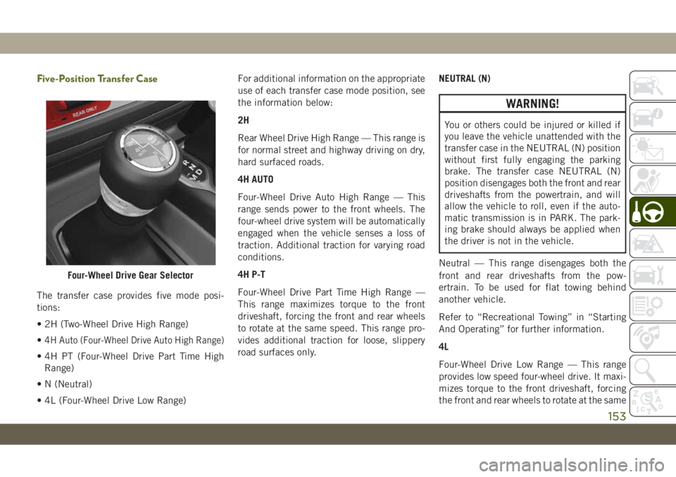
The transfer case provides five mode posi-
tions:
• 2H (Two-Wheel Drive High Range)
•
4H Auto (Four-Wheel Drive Auto High Range)
• 4H PT (Four-Wheel Drive Part Time High
Range)
• N (Neutral)
• 4L (Four-Wheel Drive Low Range)For additional information on the appropriate
use of each transfer case mode position, see
the information below:
2H
Rear Wheel Drive High Range — This range is
for normal street and highway driving on dry,
hard surfaced roads.
4H AUTO
Four-Wheel Drive Auto High Range — This
range sends power to the front wheels. The
four-wheel drive system will be automatically
engaged when the vehicle senses a loss of
traction. Additional traction for varying road
conditions.
4H P-T
Four-Wheel Drive Part Time High Range —
This range maximizes torque to the front
driveshaft, forcing the front and rear wheels
to rotate at the same speed. This range pro-
vides additional traction for loose, slippery
road surfaces only.NEUTRAL (N)
WARNING!
You or others could be injured or killed if
you leave the vehicle unattended with the
transfer case in the NEUTRAL (N) position
without first fully engaging the parking
brake. The transfer case NEUTRAL (N)
position disengages both the front and rear
driveshafts from the powertrain, and will
allow the vehicle to roll, even if the auto-
matic transmission is in PARK. The park-
ing brake should always be applied when
the driver is not in the vehicle.
Neutral — This range disengages both the
front and rear driveshafts from the pow-
ertrain. To be used for flat towing behind
another vehicle.
Refer to “Recreational Towing” in “Starting
And Operating” for further information.
4L
Four-Wheel Drive Low Range — This range
provides low speed four-wheel drive. It maxi-
mizes torque to the front driveshaft, forcing
the front and rear wheels to rotate at the same
Four-Wheel Drive Gear Selector
153
Page 157 of 348
NOTE:
• Do not attempt to make a shift while only
the front or rear wheels are spinning. The
front and rear driveshaft speeds must be
equal for the shift to take place. Shifting
while only the front or rear wheels are
spinning can cause damage to the transfer
case.
• Delayed shifts out of four-wheel drive may
be experienced due to uneven tire wear, low
or uneven tire pressures, excessive vehicle
loading, or cold temperatures.
• Shifting effort will increase with speed, this
is normal.
During cold weather, you may experience
increased effort in shifting until the transfer
case fluid warms up. This is normal.
4H Part Time/4H Auto To 4L Or 4L To 4H Part
Time/4H Auto
With the vehicle rolling at 2 to 3 mph (3 to
5 km/h), shift the transmission into NEU-
TRAL (N). While the vehicle is coasting at
2 to 3 mph (3 to 5 km/h), shift the transfer
case lever firmly to the desired position. Donot pause with the transfer case in N (Neu-
tral). Once the shift is completed, place the
transmission into DRIVE.
NOTE:
Shifting into or out of 4L is possible with the
vehicle completely stopped; however, diffi-
culty may occur due to the mating teeth not
being properly aligned. Several attempts may
be required for clutch teeth alignment and
shift completion to occur. The preferred
method is with the vehicle rolling at 2 to
3 mph (3 to 5 km/h). Avoid attempting to
engage or disengage 4L with the vehicle mov-
ing faster than 2 to 3 mph (3 to 5 km/h).
WARNING!
Failure to engage a transfer case position
completely can cause transfer case dam-
age or loss of power and vehicle control.
You could have a collision. Do not drive the
vehicle unless the transfer case is fully
engaged.
Trac-Lok Rear Axle — If Equipped
The Trac-Lok rear axle provides a constant
driving force to both rear wheels and reduces
wheel spin caused by the loss of traction at
one driving wheel. If traction differs between
the two rear wheels, the differential auto-
matically proportions the usable torque by
providing more torque to the wheel that has
traction.
Trac-Lok is especially helpful during slippery
driving conditions. With both rear wheels on a
slippery surface, a slight application of the
accelerator will supply maximum traction.
WARNING!
On vehicles equipped with a limited-slip
differential, never run the engine with one
rear wheel off the ground. The vehicle may
drive through the rear wheel remaining on
the ground and cause you to lose control of
your vehicle.
155
Page 159 of 348
Push the SWAY BAR switch to activate the
system. Push the switch again to deactivate
the system. The “Sway Bar Indicator Light”
(located in the instrument cluster) will illumi-
nate when the bar is disconnected. The
“Sway Bar Indicator Light” will flash during
activation transition, or when activation con-
ditions are not met. The stabilizer/sway bar
should remain in on-road mode during nor-
mal driving conditions.
WARNING!
Ensure the stabilizer/sway bar is recon-
nected before driving on hard surfaced
roads or at speeds above 18 mph
(29 km/h); a disconnected stabilizer/sway
bar may contribute to the loss of vehicle
control, which could result in serious in-
jury. Under certain circumstances, the
front stabilizer/sway bar enhances vehicle
stability and assists with vehicle control.
The system monitors vehicle speed and
will attempt to reconnect the stabilizer/
sway bar at speeds over 18 mph
(29 km/h). This is indicated by a flashing
or solid “Sway Bar Indicator Light.” Once
WARNING!
vehicle speed is reduced below 14 mph
(22 km/h), the system will once again
attempt to return to off-road mode.
To disconnect the stabilizer/sway bar, shift to
either 4H or 4L and push the SWAY BAR
switch to obtain the off-road position. Refer
to “Four-Wheel Drive Operation” in this sec-
tion for further information. The “Sway Bar
Indicator Light” will flash until the stabilizer/
sway bar has been fully disconnected.
NOTE:
The stabilizer/sway bar may be torque locked
due to left and right suspension height differ-
ences. This condition is due to driving sur-
face differences or vehicle loading. In order
for the stabilizer/sway bar to disconnect/
reconnect, the right and left halves of the bar
must be aligned. This alignment may require
that the vehicle be driven onto level ground or
rocked from side to side.
To return to on-road mode, push the SWAY
BAR switch again.
WARNING!
If the stabilizer/sway bar will not return to
on-road mode, the “Sway Bar Indicator
Light” will flash in the instrument cluster
and vehicle stability may be reduced. Do
not attempt to drive the vehicle over
18 mph (29 km/h). Driving faster than
18 mph (29 km/h) with a disconnected
stabilizer/sway bar may contribute to the
loss of vehicle control, which could result
in serious injury.
STOP/START SYSTEM —
AUTOMATIC
TRANSMISSION (IF
EQUIPPED)
The Stop/Start function is developed to re-
duce fuel consumption. The system will stop
the engine automatically during a vehicle
stop if the required conditions are met. Re-
leasing the brake pedal or pressing the accel-
erator pedal will automatically re-start the
engine.
157
Page 163 of 348
NOTE:
• In order to ensure proper operation, the
Speed Control System has been designed
to shut down if multiple Speed Control
functions are operated at the same time. If
this occurs, the Speed Control System can
be reactivated by pushing the Speed Con-
trol on/off button and resetting the desired
vehicle set speed.
• Do not place the gear selector in neutral
when Speed Control is activated. Doing so
will disengage the system.
WARNING!
Speed Control can be dangerous where the
system cannot maintain a constant speed.
Your vehicle could go too fast for the con-
ditions, and you could lose control and
have an accident. Do not use Speed Con-
trol in heavy traffic or on roads that are
winding, icy, snow-covered or slippery.
To Activate
Push the on/off button to activate the Speed
Control. The cruise indicator light in the in-
strument cluster display will illuminate. Toturn the system off, push the on/off button a
second time. The cruise indicator light will
turn off. The system should be turned off
when not in use.
WARNING!
Leaving the Speed Control system on when
not in use is dangerous. You could acci-
dentally set the system or cause it to go
faster than you want. You could lose con-
trol and have an accident. Always leave the
system off when you are not using it.
To Set A Desired Speed
Turn the Speed Control on.
NOTE:
The vehicle should be traveling at a steady
speed and on level ground before pushing the
SET (+) or SET (-) button.
When the vehicle has reached the desired
speed, push the SET (+) or SET (-) button and
release. Release the accelerator and the ve-
hicle will operate at the selected speed.
To Vary The Speed Setting
To Increase Speed
When the Speed Control is set, you can in-
crease speed by pushing the SET(+)button.
The driver’s preferred units can be selected
through the instrument panel settings. Refer
to ”Instrument Cluster Display” in “Getting
To Know Your Instrument Panel” in your Own-
er’s Manual for more information. The speed
increment shown is dependent on the chosen
speed unit of U.S. (mph) or Metric (km/h):
U.S. Speed (mph)
• Pushing the SET(+)button once will result
in a 1 mph increase in set speed. Each
subsequent tap of the button results in an
increase of 1 mph.
• If the button is continually pushed, the set
speed will continue to increase until the
button is released, then the new set speed
will be established.
161
Page 164 of 348
Metric Speed (km/h)
• Pushing the SET(+)button once will result
in a 1 km/h increase in set speed. Each
subsequent tap of the button results in an
increase of 1 km/h.
• If the button is continually pushed, the set
speed will continue to increase until the
button is released, then the new set speed
will be established.
To Decrease Speed
When the Speed Control is set, you can de-
crease speed by pushing the SET(-)button.
The driver’s preferred units can be selected
through the instrument panel settings. Refer
to ”Instrument Cluster Display” in “Getting
To Know Your Instrument Panel” in your Own-
er’s Manual for more information. The speed
increment shown is dependent on the chosen
speed unit of U.S. (mph) or Metric (km/h):
U.S. Speed (mph)
• Pushing the SET(-)button once will result
in a 1 mph decrease in set speed. Each
subsequent tap of the button results in a
decrease of 1 mph.• If the button is continually pushed, the set
speed will continue to decrease until the
button is released, then the new set speed
will be established.
Metric Speed (km/h)
• Pushing the SET(-)button once will result
in a 1 km/h decrease in set speed. Each
subsequent tap of the button results in a
decrease of 1 km/h.
• If the button is continually pushed, the set
speed will continue to decrease until the
button is released, then the new set speed
will be established.
To Accelerate For Passing
Press the accelerator as you would normally.
When the pedal is released, the vehicle will
return to the set speed.
Using Speed Control On Hills
The transmission may downshift on hills to
maintain the vehicle set speed.
NOTE:
The Speed Control system maintains speed
up and down hills. A slight speed change on
moderate hills is normal.On steep hills, a greater speed loss or gain
may occur so it may be preferable to drive
without Speed Control.
WARNING!
Speed Control can be dangerous where the
system cannot maintain a constant speed.
Your vehicle could go too fast for the con-
ditions, and you could lose control and
have an accident. Do not use Speed Con-
trol in heavy traffic or on roads that are
winding, icy, snow-covered or slippery.
To Resume Speed
To resume a previously set speed, push the
RES button and release. Resume can be used
at any speed above 20 mph (32 km/h).
To Deactivate
A soft tap on the brake pedal, pushing the
CANC (cancel) button, or normal brake pres-
sure while slowing the vehicle will deactivate
the speed control without erasing the set
speed from memory.
STARTING AND OPERATING
162
Page 166 of 348
• When you turn ParkSense OFF, the instru-
ment cluster display will read
“PARKSENSE OFF.” Furthermore, once
you turn ParkSense OFF, it remains off until
you turn it on again, even if you cycle the
ignition.
• ParkSense, when on, will reduce the vol-
ume of the radio when it is sounding a tone.
• Clean the ParkSense sensors regularly, tak-
ing care not to scratch or damage them.
The sensors must not be covered with ice,
snow, slush, mud, dirt or debris. Failure to
do so can result in the system not working
properly. The ParkSense system might not
detect an obstacle behind the fascia/
bumper, or it could provide a false indica-
tion that an obstacle is behind the fascia/
bumper.
• Use the ParkSense switch to turn the
ParkSense system OFF if objects such as
bicycle carriers, trailer hitches, etc. are
placed within 12 inches (30 cm) from the
rear fascia/bumper. Failure to do so can
result in the system misinterpreting a close
object as a sensor problem, causing the“PARKSENSE UNAVAILABLE SERVICE
REQUIRED” message to be displayed in
the instrument cluster display.
• The operation of the rear sensors is auto-
matically deactivated when the trailer's
electric plug is inserted in the vehicle's tow
hook socket. The rear sensors are automati-
cally reactivated when the trailer's cable
plug is removed.
WARNING!
• Drivers must be careful when backing up
even when using ParkSense. Always
check carefully behind your vehicle,
look behind you, and be sure to check
for pedestrians, animals, other vehicles,
obstructions, and blind spots before
backing up. You are responsible for
safety and must continue to pay atten-
tion to your surroundings. Failure to do
so can result in serious injury or death.
• Before using ParkSense, it is strongly
recommended that the ball mount and
hitch ball assembly is disconnected
from the vehicle when the vehicle is not
used for towing. Failure to do so can
WARNING!
result in injury or damage to vehicles or
obstacles because the hitch ball will be
much closer to the obstacle than the
rear fascia when the loudspeaker sounds
the continuous tone. Also, the sensors
could detect the ball mount and hitch
ball assembly, depending on its size and
shape, giving a false indication that an
obstacle is behind the vehicle.
CAUTION!
• ParkSense is only a parking aid and it is
unable to recognize every obstacle, in-
cluding small obstacles. Parking curbs
might be temporarily detected or not
detected at all. Obstacles located above
or below the sensors will not be detected
when they are in close proximity.
• The vehicle must be driven slowly when
using ParkSense in order to be able to
stop in time when an obstacle is de-
tected. It is recommended that the
driver looks over his/her shoulder when
using ParkSense.STARTING AND OPERATING
164
Page 167 of 348
PARKVIEW REAR BACK UP
CAMERA — IF EQUIPPED
The ParkView Rear Back Up Camera allows
you to see an on-screen image of the rear
surroundings of your vehicle whenever the
gear selector is put into REVERSE. The image
will be displayed in the touchscreen display
along with a caution note to “check entire
surroundings” across the top of the screen.
After five seconds this note will disappear.
The ParkView camera is located on the rear of
the vehicle in the center of the spare tire.
Manual Activation Of The Rear View Camera
1. Press the “Controls” button located on
the bottom of the Uconnect display.
2. Press the “Backup Camera” button to
turn the Rear View Camera system on.
NOTE:
The ParkView Rear Back Up Camera has
programmable modes of operation that may
be selected through the Uconnect System.
Refer to “Uconnect Settings” in “Multime-
dia” in your Owner’s Manual for further infor-
mation.When the vehicle is shifted out of REVERSE
(with camera delay turned off), the rear cam-
era mode is exited and the previous screen
appears again. When the vehicle is shifted
out of REVERSE (with camera delay turned
on), the camera image will continue to be
displayed for up to ten seconds after shifting
out of REVERSE unless the vehicle speed
exceeds 8 mph (13 km/h), the vehicle is
shifted into PARK, the vehicle’s ignition is
cycled to the OFF position, or the user
presses image defeat [X] to exit out of the
camera video display.
NOTE:
• If the vehicle speed remains below 8 mph
(13 km/h), the Rear View Camera image will
be displayed continuously until deactivated
via the touchscreen button “X”, the vehicle
is shifted into PARK, or the ignition is
placed in the OFF position.
• The touchscreen button “X” to disable dis-
play of the camera image is made available
ONLY when the vehicle is not in REVERSE.
When enabled, active guide lines are overlaid
on the image to illustrate the width of the
vehicle and its projected backup path basedon the steering wheel position. A dashed
center line overlay indicates the center of the
vehicle to assist with parking or aligning to a
hitch/receiver.
When enabled, fixed guide lines are overlaid
on the image to illustrate the width of the
vehicle.
Different colored zones indicate the distance
to the rear of the vehicle.
WARNING!
Drivers must be careful when backing up
even when using the ParkView Rear Back
Up Camera. Always check carefully behind
your vehicle, and be sure to check for
pedestrians, animals, other vehicles, ob-
structions, or blind spots before backing
up. You are responsible for the safety of
your surroundings and must continue to
pay attention while backing up. Failure to
do so can result in serious injury or death.
165
Page 168 of 348
CAUTION!
• To avoid vehicle damage, ParkView
should only be used as a parking aid.
The ParkView camera is unable to view
every obstacle or object in your drive
path.
• To avoid vehicle damage, the vehicle
must be driven slowly when using
ParkView to be able to stop in time when
an obstacle is seen. It is recommended
that the driver look frequently over his/
her shoulder when using ParkView.
NOTE:
If snow, ice, mud, or any foreign substance
builds up on the camera lens, clean the lens,
rinse with water, and dry with a soft cloth. Do
not cover the lens.
REFUELING THE VEHICLE
Fuel Filler Cap
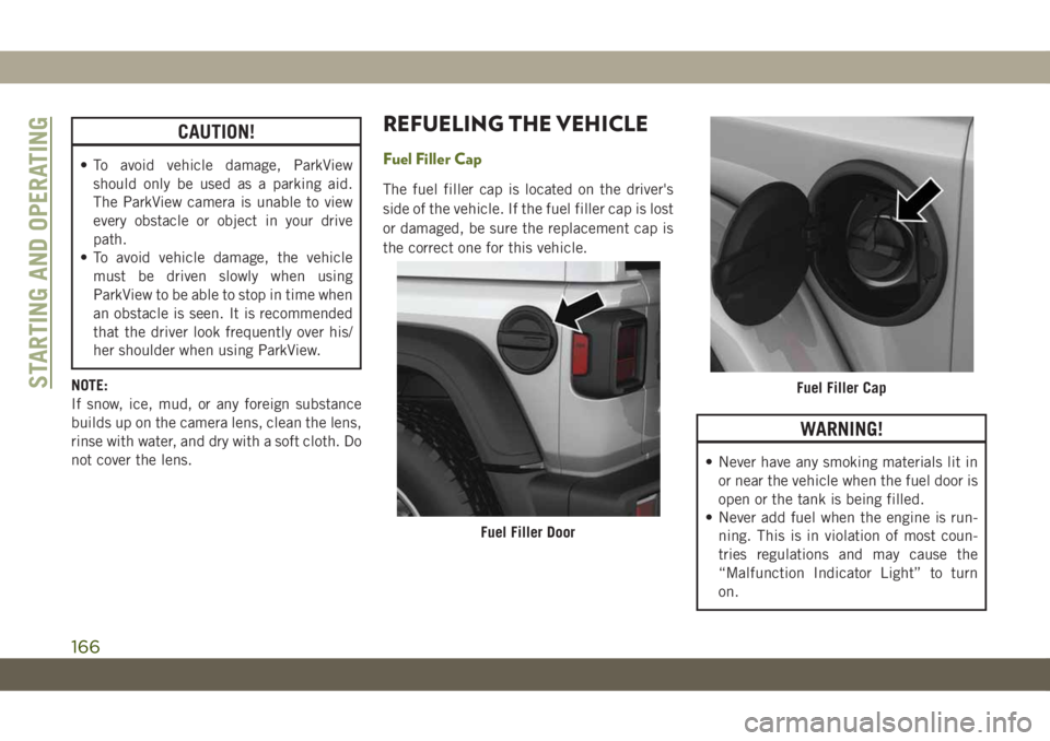
The fuel filler cap is located on the driver's
side of the vehicle. If the fuel filler cap is lost
or damaged, be sure the replacement cap is
the correct one for this vehicle.
WARNING!
• Never have any smoking materials lit in
or near the vehicle when the fuel door is
open or the tank is being filled.
• Never add fuel when the engine is run-
ning. This is in violation of most coun-
tries regulations and may cause the
“Malfunction Indicator Light” to turn
on.
Fuel Filler Door
Fuel Filler CapSTARTING AND OPERATING
166