park JEEP WRANGLER 2DOORS 2019 Owner handbook (in English)
[x] Cancel search | Manufacturer: JEEP, Model Year: 2019, Model line: WRANGLER 2DOORS, Model: JEEP WRANGLER 2DOORS 2019Pages: 348, PDF Size: 6.5 MB
Page 17 of 348
IGNITION SWITCH
Keyless Enter-N-Go — Ignition
This feature allows the driver to operate the
ignition switch with the push of a button as
long as the key fob is in the passenger com-
partment.
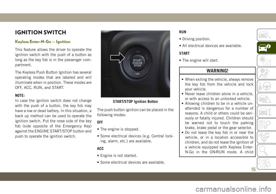
The Keyless Push Button Ignition has several
operating modes that are labeled and will
illuminate when in position. These modes are
OFF, ACC, RUN, and START.
NOTE:
In case the ignition switch does not change
with the push of a button, the key fob may
have a low or dead battery. In this situation, a
back up method can be used to operate the
ignition switch. Put the nose side of the key
fob (side opposite of the Emergency Key)
against the ENGINE START/STOP button and
push to operate the ignition switch.The push button ignition can be placed in the
following modes:
OFF
• The engine is stopped.
• Some electrical devices (e.g. Central lock-
ing, alarm, etc.) are available.
ACC
• Engine is not started.
• Some electrical devices are available.RUN
• Driving position.
• All electrical devices are available.
START
• The engine will start.
WARNING!
• When exiting the vehicle, always remove
the key fob from the vehicle and lock
your vehicle.
• Never leave children alone in a vehicle,
or with access to an unlocked vehicle.
• Allowing children to be in a vehicle un-
attended is dangerous for a number of
reasons. A child or others could be seri-
ously or fatally injured. Children should
be warned not to touch the parking
brake, brake pedal or the gear selector.
• Do not leave the key fob in or near the
vehicle, or in a location accessible to
children, and do not leave the ignition of
a vehicle equipped with Keyless Enter-
N-Go in the ON/RUN mode. A child
START/STOP Ignition Button
15
Page 18 of 348
WARNING!
could operate power windows, other con-
trols, or move the vehicle.
• Do not leave children or animals inside
parked vehicles in hot weather. Interior
heat build-up may cause serious injury
or death.
CAUTION!
An unlocked vehicle is an invitation for
thieves. Always remove key fob from the
vehicle and lock all doors when leaving the
vehicle unattended.
NOTE:
Refer to "Starting The Engine," in "Starting
And Operating" in the Owner’s Manual for
further information.
REMOTE STARTING
SYSTEM — IF EQUIPPED
This system uses the key fob to
start the engine conveniently from
outside the vehicle while still main-
taining security. The system has a
range of 328 ft (100 m).
The Remote Starting System also activates
the Climate Control, vented seats (if
equipped) in temperatures above 80° F
(26.7° C), and the heated seats (if
equipped), and heated steering wheel (if
equipped) in temperatures below 40° F
(4.4° C). Refer to “Heated Seats” in “Getting
To Know Your Vehicle” in the Owner’s Manual
for further information.
NOTE:
• The vehicle must be equipped with an
automatic transmission to be equipped
with Remote Start.
• Obstructions between the vehicle and key
fob may reduce this range.
How To Use Remote Start
• Push Remote Start button on the key fob
twice within five seconds. Pushing the Re-
mote Start button a third time shuts the
engine off.
• To drive the vehicle, push unlock button,
and place the ignition in the ON/RUN po-
sition.
• With remote start, the engine will only run
for 15 minutes (timeout) unless the igni-
tion key is placed in the ON/RUN position.
• The vehicle must be started with the key
after two consecutive timeouts.
All of the following conditions must be met
before the engine will remote start:
• Gear Selector in PARK
• Doors closed
• Hood closed
• Swing Gate closed
• Hazard switch off
• Brake switch inactive (brake pedal not
pushed)
• Battery at an acceptable charge level
GETTING TO KNOW YOUR VEHICLE
16
Page 19 of 348
• System not disabled from previous remote
start event
• Vehicle alarm system indicator flashing
• Ignition in STOP/OFF position
• Fuel level meets minimum requirement
• All removable doors must not be removed
• Malfunction indicator light not illuminated
WARNING!
• Do not start or run an engine in a closed
garage or confined area. Exhaust gas
contains Carbon Monoxide (CO) which
is odorless and colorless. Carbon Mon-
oxide is poisonous and can cause seri-
ous injury or death when inhaled.
• Keep key fobs away from children. Op-
eration of the Remote Start System,
windows, door locks or other controls
could cause serious injury or death.
To Enter Remote Start Mode
Push and release the Remote Start button on
the key fob twice within five seconds. The
vehicle doors will lock, the turn signals will
flash twice, and the horn will chirp twice.
Then the engine will start, and the vehicle
will remain in the Remote Start mode for a
15-minute cycle.
NOTE:
• If an engine fault is present or fuel level is
low, the vehicle will start and then shut
down in 10 seconds.
• The park lamps will turn on and remain on
during Remote Start mode.
• For security, power window operation is
disabled when the vehicle is in the Remote
Start mode.
• The engine can be started two consecutive
times (two 15-minute cycles) with the key
fob. However, the ignition must be placed
in the ON/RUN position before you can
repeat the start sequence for a third cycle.
VEHICLE SECURITY ALARM
— IF EQUIPPED
The vehicle security alarm monitors the ve-
hicle doors for unauthorized entry and the
ignition switch for unauthorized operation.
When the alarm is activated, the interior
switches for door locks are disabled. The
vehicle security alarm provides both audible
and visible signals. If something triggers the
alarm, the vehicle security alarm will provide
the following audible and visible signals: the
horn will pulse, the park lamps and/or turn
signals will flash, and the vehicle security
light in the instrument cluster will flash.
To Arm The System
Follow these steps to arm the vehicle security
alarm:
1. Make sure the vehicle’s ignition is cycled
to the “OFF” position (refer to "Starting
The Engine" in "Starting And Operating"
for further information).
17
Page 37 of 348
MIRRORS
Heated Mirrors — If Equipped
These mirrors are heated to melt frost or ice.
This feature will be activated whenever you
turn on the rear window defroster (if
equipped). Refer to “Climate Controls” in
“Getting To Know Your Vehicle” for further
information.
EXTERIOR LIGHTS
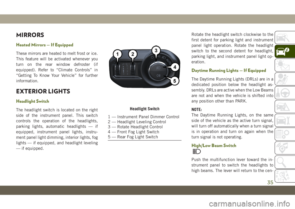
Headlight Switch
The headlight switch is located on the right
side of the instrument panel. This switch
controls the operation of the headlights,
parking lights, automatic headlights — if
equipped, instrument panel lights, instru-
ment panel light dimming, interior lights, fog
lights — if equipped, and headlight leveling
— if equipped.Rotate the headlight switch clockwise to the
first detent for parking light and instrument
panel light operation. Rotate the headlight
switch to the second detent for headlight,
parking light, and instrument panel light op-
eration.
Daytime Running Lights — If Equipped
The Daytime Running Lights (DRLs) are in a
dedicated position below the headlight as-
sembly. DRLs are active when the Low Beams
are not and when the vehicle is shifted into
any position other than PARK.
NOTE:
The Daytime Running Lights, on the same
side of the vehicle as the active turn signal,
will turn off automatically when a turn signal
is in operation and turn on again when the
turn signal is not operating.
High/Low Beam Switch
Push the multifunction lever toward the in-
strument panel to switch the headlights to
high beams. The lever will return to the cen-
Headlight Switch
1 — Instrument Panel Dimmer Control
2 — Headlight Leveling Control
3 — Rotate Headlight Control
4 — Front Fog Light Switch
5 — Rear Fog Light Switch
35
Page 39 of 348
Lane Change Assist — If Equipped
Tap the multifunction lever up or down once,
without moving beyond the detent, and the
turn signal (right or left) will flash three times
then automatically turn off.
Lights-On Reminder
If the headlights, parking lights, or cargo
lights are left on after the ignition is turned
OFF, a chime will sound when the driver’s
door is opened.
Headlight Leveling System — If Equipped
Your vehicle may be equipped with a head-
light leveling system. This system allows the
driver to maintain proper headlight beam
position with the road surface regardless of
vehicle load.
The control switch is located on the instru-
ment panel next to the dimmer control.
To operate, rotate the control switch until the
appropriate number, which corresponds to
the load listed on the chart, aligns with the
indicator line on the switch.
0/1Driver only, or driver and
front passenger.
2All seating positions occu-
pied, plus an evenly dis-
tributed load in the lug-
gage compartment. The
total weight of passengers
and load does not exceed
the maximum load capacity
of the vehicle.
3Driver, plus an evenly dis-
tributed load in the lug-
gage compartment. The
total weight of the driver
and load does not exceed
the maximum load capacity
of the vehicle.
WINDSHIELD WIPERS AND
WASHERS
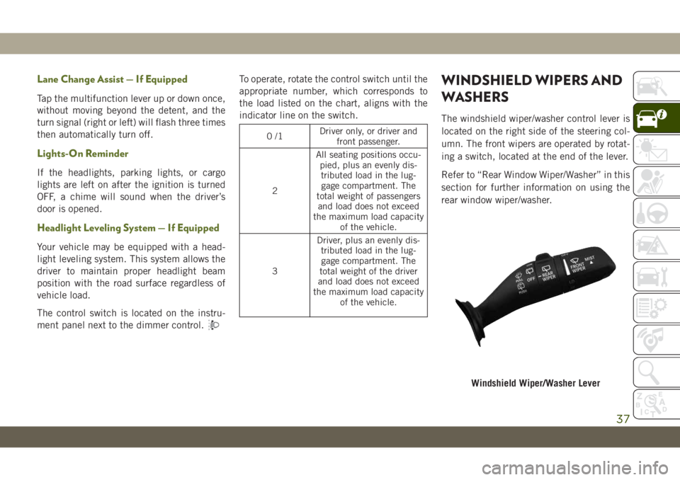
The windshield wiper/washer control lever is
located on the right side of the steering col-
umn. The front wipers are operated by rotat-
ing a switch, located at the end of the lever.
Refer to “Rear Window Wiper/Washer” in this
section for further information on using the
rear window wiper/washer.
Windshield Wiper/Washer Lever
37
Page 40 of 348
Windshield Wiper Operation
Rotate the end of the lever upward to the
second detent past the intermittent settings
for low-speed wiper operation. Rotate the end
of the lever upward to the third detent past
the intermittent settings for high-speed wiper
operation.
CAUTION!
In cold weather, always turn off the wiper
switch and allow the wipers to return to the
park position before turning off the en-
gine. If the wiper switch is left on and the
wipers freeze to the windshield, damage to
the wiper motor may occur when the ve-
hicle is restarted.
NOTE:
Do not operate the windshield wipers with the
blades lifted from the windshield.
Intermittent Wiper System
Use the intermittent wiper when weather
conditions make a single wiping cycle, with a
variable pause between cycles, desirable. Ro-tate the end of the lever to the first detent
position for one of four intermittent settings.
The delay cycle can be set anywhere between
1 to 18 seconds.
NOTE:
The wiper delay times depend on vehicle
speed. If the vehicle is moving less than
10 mph (16 km/h), delay times will be
doubled.
Windshield Washers
To use the washer, pull the lever toward you
and hold while spray is desired. If the lever is
pulled while in the delay range, the wiper will
start and continue to operate for two or three
wipe cycles after the lever is released. Then,
the intermittent interval previously selected
will resume.
If the lever is pulled while in the off position,
the wipers will operate for two or three wipe
cycles. Then, the wipers will turn off.
WARNING!
Sudden loss of visibility through the wind-
shield could lead to a collision. You might
WARNING!
not see other vehicles or other obstacles.
To avoid sudden icing of the windshield
during freezing weather, warm the wind-
shield with the defroster before and during
windshield washer use.
Mist Feature
Push upward on the wiper lever to activate a
single wipe to clear off road mist or spray
from a passing vehicle. As long as the lever is
held up, the wipers will continue to operate.
NOTE:
The mist feature does not activate the washer
pump; therefore, no washer fluid will be
sprayed on the windshield. The wash func-
tion must be used in order to spray the
windshield with washer fluid.
Rear Window Wiper/Washer — If Equipped
A rotary switch on the center portion of the
windshield wiper/washer lever controls the
operation of the rear wiper/washer function.
GETTING TO KNOW YOUR VEHICLE
38
Page 41 of 348
Rotate the switch upward to the first detent
position for intermittent operation and to the
second detent for continuous rear wiper op-
eration.
Push the wiper lever toward the instrument
panel to activate the rear washer. The washer
pump and wiper will continue to operate as
long as the lever is held.
If the rear wiper is operating when the igni-
tion is placed in the OFF position, the wiper
will automatically return to the “park” posi-
tion. When the vehicle is restarted, the wiper
will resume function at whichever position
the switch is set at.CLIMATE CONTROLS
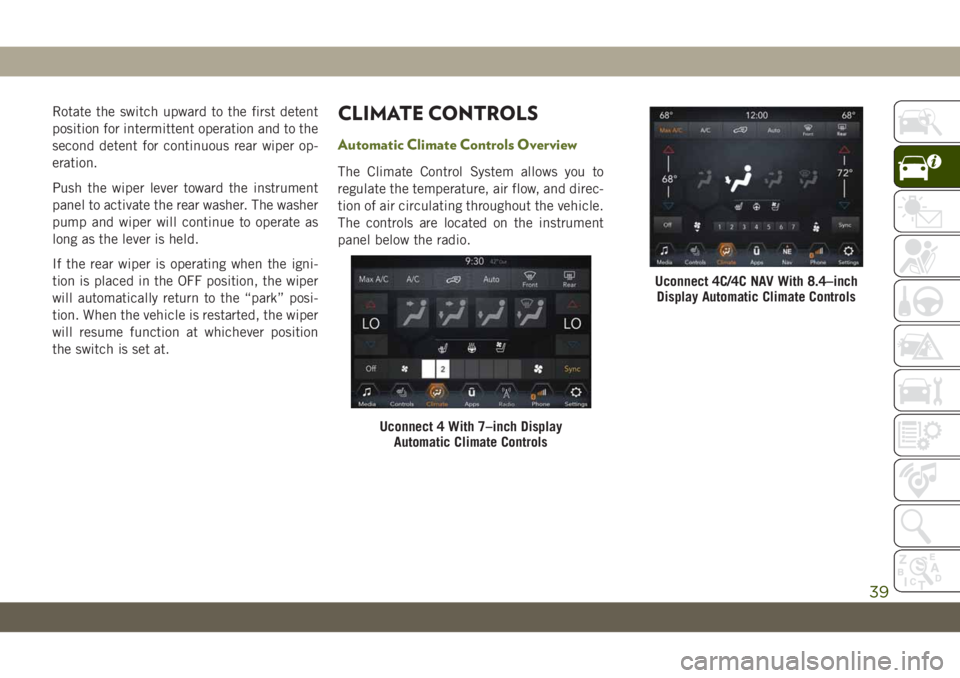
Automatic Climate Controls Overview
The Climate Control System allows you to
regulate the temperature, air flow, and direc-
tion of air circulating throughout the vehicle.
The controls are located on the instrument
panel below the radio.
Uconnect 4 With 7–inch Display
Automatic Climate Controls
Uconnect 4C/4C NAV With 8.4–inch
Display Automatic Climate Controls
39
Page 68 of 348
MESSAGE DESCRIPTION
Engine Will Not Start Service Ad-
Blue System See DealerNOTE:
• The display may take up to five seconds to update after adding 2 gallons (7.5 Liters) or more of AdBlue
(UREA) to the AdBlue (UREA) tank. If you have a fault related to the AdBlue (UREA) system, the display
may not update to the new level. See an authorized dealer for service.
• AdBlue freezes at temperatures lower than 51.8°F (11°C). If the car stands for a long time at this tem-
perature, refilling could be difficult. For this reason, it is advised to park the vehicle in a garage and/or
heated environment, and wait for the AdBlue (UREA) to return to liquid state before topping up.
Gasoline Particulate Filter (GPF) System Messages — If Equipped:
Exhaust System Service Re-
quiredThe engine control unit has detected an issue with the gasoline particulate filter system. See an autho-
rized dealer.
Exhaust System Regeneration in
Process Continue DrivingThe regeneration procedure is controlled automatically by the engine control unit according to the filter
conditions and car use conditions. The following may occur during regeneration: increased levels of noise
vibration and harshness (NVH) and reduced engine performance. The driver should continue driving nor-
mally. This message will continue to appear until regeneration is complete.
Exhaust System Regeneration
CompleteThe exhaust gas filter regeneration has been completed. This message will briefly appear.
WARNING LIGHTS AND
MESSAGES
The warning/indicator lights will illuminate in
the instrument panel together with a dedi-
cated message and/or acoustic signal when
applicable. These indications are indicative
and precautionary and as such must not be
considered as exhaustive and/or alternativeto the information contained in the Owner’s
Manual, which you are advised to read care-
fully in all cases. Always refer to the informa-
tion in this chapter in the event of a failure
indication. All active telltales will display first
if applicable. The system check menu may
appear different based upon equipment op-
tions and current vehicle status. Some tell-
tales are optional and may not appear.
Red Warning Lights
— Air Bag Warning Light
This warning light will illuminate to indicate
a fault with the air bag, and will turn on for
four to eight seconds as a bulb check when
the ignition is placed in the ON/RUN or
ACC/ON/RUN position. This light will illumi-
nate with a single chime when a fault with the
GETTING TO KNOW YOUR INSTRUMENT PANEL
66
Page 69 of 348
air bag has been detected, it will stay on until
the fault is cleared. If the light is either not on
during startup, stays on, or turns on while
driving, have the system inspected at an
authorized dealer as soon as possible.
— Brake Warning Light
This warning light monitors various brake
functions, including brake fluid level and
parking brake application. If the brake light
turns on it may indicate that the parking
brake is applied, that the brake fluid level is
low, or that there is a problem with the
anti-lock brake system.
If the light remains on when the parking
brake has been disengaged, and the fluid
level is at the full mark on the master cylinder
reservoir, it indicates a possible brake hy-
draulic system malfunction or that a problem
with the Brake Booster has been detected by
the Anti-Lock Brake System (ABS) / Elec-
tronic Stability Control (ESC) system. In this
case, the light will remain on until the condi-
tion has been corrected. If the problem is
related to the brake booster, the ABS pump
will run when applying the brake, and a brake
pedal pulsation may be felt during each stop.
The dual brake system provides a reserve brak-
ing capacity in the event of a failure to a portion
of the hydraulic system. A leak in either half of
the dual brake system is indicated by the Brake
Warning Light, which will turn on when the
brake fluid level in the master cylinder has
dropped below a specified level.
The light will remain on until the cause is
corrected.
NOTE:
The light may flash momentarily during sharp
cornering maneuvers, which change fluid
level conditions. The vehicle should have
service performed, and the brake fluid level
checked.
If brake failure is indicated, immediate repair
is necessary.
WARNING!
Driving a vehicle with the red brake light
on is dangerous. Part of the brake system
may have failed. It will take longer to stop
the vehicle. You could have a collision.
Have the vehicle checked immediately.Vehicles equipped with the Anti-Lock Brake
System (ABS) are also equipped with Elec-
tronic Brake Force Distribution (EBD). In the
event of an EBD failure, the Brake Warning
Light will turn on along with the ABS Light.
Immediate repair to the ABS system is re-
quired.
Operation of the Brake Warning Light can be
checked by turning the ignition switch from
the OFF position to the ON/RUN position.
The light should illuminate for approximately
four seconds. The light should then turn off
unless the parking brake is applied or a brake
fault is detected. If the light does not illumi-
nate, have the light inspected by an autho-
rized dealer.
The light also will turn on when the parking
brake is applied with the ignition switch in
the ON/RUN position.
NOTE:
This light shows only that the parking brake is
applied. It does not show the degree of brake
application.
67
Page 70 of 348
— Battery Charge Warning Light
This warning light will illuminate when the
battery is not charging properly. If it stays on
while the engine is running, there may be a
malfunction with the charging system. Con-
tact an authorized dealer as soon as possible.
This indicates a possible problem with the
electrical system or a related component.
— Door Open Warning Light
This indicator will illuminate when a door is
ajar/open and not fully closed.
NOTE:
If the vehicle is moving, there will also be a
single chime.
— Electric Power Steering Fault
Warning Light
This warning light will turn on when there's a
fault with the EPS (Electric Power Steering)
system. Refer to “Power Steering” in “Start-
ing And Operating” in the Owner’s Manual for
further information.
WARNING!
Continued operation with reduced assist
could pose a safety risk to yourself and
others. Service should be obtained as soon
as possible.
— Electronic Throttle Control (ETC)
Warning Light
This warning light will illuminate to indicate
a problem with the Electronic Throttle Con-
trol (ETC) system. If a problem is detected
while the vehicle is running, the light will
either stay on or flash depending on the
nature of the problem. Cycle the ignition
when the vehicle is safely and completely
stopped and the transmission is placed in the
PARK position. The light should turn off. If
the light remains on with the vehicle running,
your vehicle will usually be drivable; however,
see an authorized dealer for service as soon
as possible.
NOTE:
This light may turn on if the accelerator and
brake pedals are pressed at the same time.If the light continues to flash when the ve-
hicle is running, immediate service is re-
quired and you may experience reduced per-
formance, an elevated/rough idle, or engine
stall and your vehicle may require towing.
The light will come on when the ignition is
placed in the ON/RUN or ACC/ON/RUN posi-
tion and remain on briefly as a bulb check. If
the light does not come on during starting,
have the system checked by an authorized
dealer.
— Engine Coolant Temperature Warn-
ing Light
This warning light warns of an overheated
engine condition. If the engine coolant tem-
perature is too high, this indicator will illumi-
nate and a single chime will sound. If the
temperature reaches the upper limit, a con-
tinuous chime will sound for four minutes or
until the engine is able to cool: whichever
comes first.
If the light turns on while driving, safely pull
over and stop the vehicle. If the A/C system is
on, turn it off. Also, shift the transmission
GETTING TO KNOW YOUR INSTRUMENT PANEL
68