In case of emergency JEEP WRANGLER UNLIMITED 2018 Owner handbook (in English)
[x] Cancel search | Manufacturer: JEEP, Model Year: 2018, Model line: WRANGLER UNLIMITED, Model: JEEP WRANGLER UNLIMITED 2018Pages: 348, PDF Size: 6.5 MB
Page 190 of 348
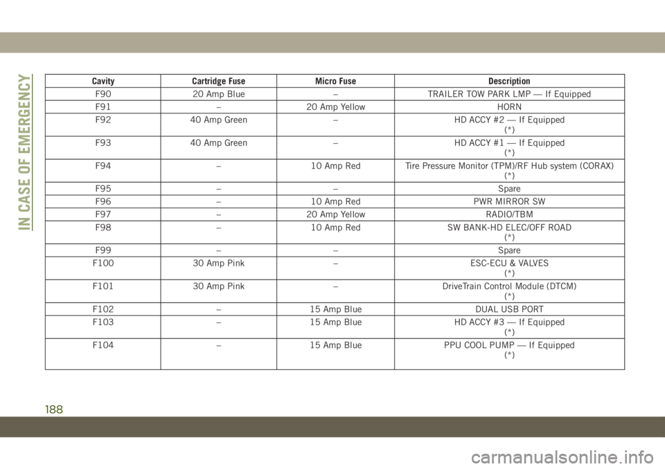
Cavity Cartridge Fuse Micro Fuse Description
F90 20 Amp Blue – TRAILER TOW PARK LMP — If Equipped
F91 – 20 Amp Yellow HORN
F92 40 Amp Green – HD ACCY #2 — If Equipped
(*)
F93 40 Amp Green – HD ACCY #1 — If Equipped
(*)
F94 – 10 Amp Red Tire Pressure Monitor (TPM)/RF Hub system (CORAX)
(*)
F95 – – Spare
F96 – 10 Amp Red PWR MIRROR SW
F97 – 20 Amp Yellow RADIO/TBM
F98 – 10 Amp Red SW BANK-HD ELEC/OFF ROAD
(*)
F99 – – Spare
F100 30 Amp Pink – ESC-ECU & VALVES
(*)
F101 30 Amp Pink – DriveTrain Control Module (DTCM)
(*)
F102 – 15 Amp Blue DUAL USB PORT
F103 – 15 Amp Blue HD ACCY #3 — If Equipped
(*)
F104 – 15 Amp Blue PPU COOL PUMP — If Equipped
(*)
IN CASE OF EMERGENCY
188
Page 192 of 348
WARNING!
• Being under a jacked-up vehicle is dan-
gerous. The vehicle could slip off the
jack and fall on you. You could be
crushed. Never put any part of your body
under a vehicle that is on a jack. If you
need to get under a raised vehicle, take
it to a service center where it can be
raised on a lift.
• Never start or run the engine while the
vehicle is on a jack.
• The jack is designed to be used as a tool
for changing tires only. The jack should
not be used to lift the vehicle for service
purposes. The vehicle should be jacked
on a firm level surface only. Avoid ice or
slippery areas.
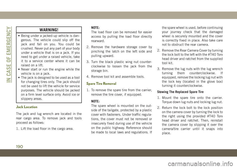
Jack Location
The jack and lug wrench are located in the
rear cargo area. To remove jack and tools
proceed as follows:
1. Lift the load floor in the cargo area.NOTE:
The load floor can be removed for easier
access by pulling the load floor directly
rearward.
2. Remove the hardware storage cover by
pinching the latch on the left side and
pulling upward.
3. Turn the black plastic wing nut counter-
clockwise to loosen the jack from the
storage bin.
4. Remove tool kit and assemble tools.
Spare Tire Removal
1. To remove the spare tire from the carrier,
remove the tire cover, if equipped.
NOTE:
The spare wheel is mounted on the out-
side of the tailgate, protected by a plastic
cover with fasteners. Under traffic regula-
tions, the cover must not be removed or
insecurely fixed during use of the vehicle
on the public highway. Reference should
be made to local laws and regulations. Ifthe spare wheel is used, before continuing
your journey check that the damaged
wheel is securely mounted and the cover
is correctly fixed in place. Also take care
not to obstruct the rear camera.
2. Remove the Rear Camera Cover by turning
the lock bolt to the left with the #T40 Torx
head driver and ratchet from the supplied
tool kit.
3. Remove the lug nuts with the lug wrench
turning them counterclockwise. If
equipped, remove the locking lug nut with
the lock key (located in the glove box)
turning it counterclockwise.
Stowing The Replaced Spare Tire
1. Mount the spare tire onto the carrier.
Torque down lug nuts and locking lug nut.
2. Return the lock bolt to the lock position
on the camera cover by turning the lock to
the right using the provided #T40 Torx
head driver and ratchet. Then, reinstall
the camera cover by slipping it over the
camera/tire carrier until it snaps into
place.
IN CASE OF EMERGENCY
190
Page 194 of 348
WARNING!
• If working on or near a roadway, be
extremely careful of motor traffic.
• To assure that spare tires, flat or in-
flated, are securely stowed, spares must
be stowed with the valve stem facing the
ground.
CAUTION!
Do not attempt to raise the vehicle by
jacking on locations other than those indi-
cated.
1. Remove the spare tire, jack and tools from
the stored location.
2. Loosen (but do not remove) the wheel lug
nuts by turning them to the left one turn
while the wheel is still on the ground.
3. Assemble the jack and jacking tools. Con-
nect the jack handle driver to the exten-
sion, then to the lug wrench.
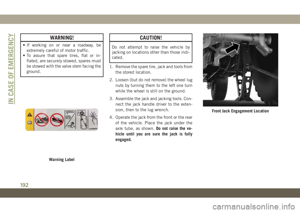
4. Operate the jack from the front or the rear
of the vehicle. Place the jack under the
axle tube, as shown.Do not raise the ve-
hicle until you are sure the jack is fully
engaged.
Warning Label
Front Jack Engagement Location
IN CASE OF EMERGENCY
192
Page 196 of 348
Road Tire Installation
1. Mount the road tire on the axle.
2. Install the remaining lug nuts with the
cone shaped end of the nut toward the
wheel. Lightly tighten the lug nuts.
WARNING!
To avoid the risk of forcing the vehicle off
the jack, do not tighten the wheel nuts
fully until the vehicle has been lowered.
Failure to follow this warning may result in
serious injury.
3. Lower the vehicle to the ground by turning
the jack handle counterclockwise.
4. Finish tightening the lug nuts. Push down
on the wrench while at the end of the
handle for increased leverage. Tighten the
lug nuts in a star pattern until each nut
has been tightened twice. For the correct
lug nut torque refer to “Torque Specifica-
tions” in “Technical Specifications”. If in
doubt about the correct tightness, have
them checked with a torque wrench by an
authorized dealer or service station.5. After 25 miles (40 km), check the lug nut
torque with a torque wrench to ensure that
all lug nuts are properly seated against the
wheel.
Declaration Of Conformance
1. The undersigned, FlexNGate, represent-
ing the manufacturer, herewith declares
that the machinery described below ful-
fills all relevant provisions of:
•The EC-directive 2006/42/EC on
Machinery
2. Description of machinery.
a) Generic Denomination: Vehicle Jack
b) Function: Lifting Vehicle
d) Ve-
hicle
Modelc) Model
Codef) Work-
ing Loade) Jack
Type
Jeep
WranglerJL 1000 kg
MaxFGLF2
3. Manufacturers (1):
FlexNGate Seeburn, a division of Ventra
Group Co
P.O. Box 1170, 65 Industrial Road, Totten-
ham, ON CANADA L0G 1W04. Manufacturers (2):
FlexNGate Querétaro Ventramex, S.A. de
C.V
Av. Manantiales No. 3
Parque Industrial Bernardo Quintana, El
Marqués Querétaro C.P. 76249 – Mexico
5. Legal Person authorized to compile the
technical file:
FlexNGate – Barcelona
Avda de la Riera, 7-9
Sant Just Desvern, Barcelona, SPAIN 08960
6. References to harmonized standards:
PF-90065
7. Done at: Bradford, ON CANADA
8. Date: 10/02/2017FlexNGate Representative
IN CASE OF EMERGENCY
194
Page 198 of 348
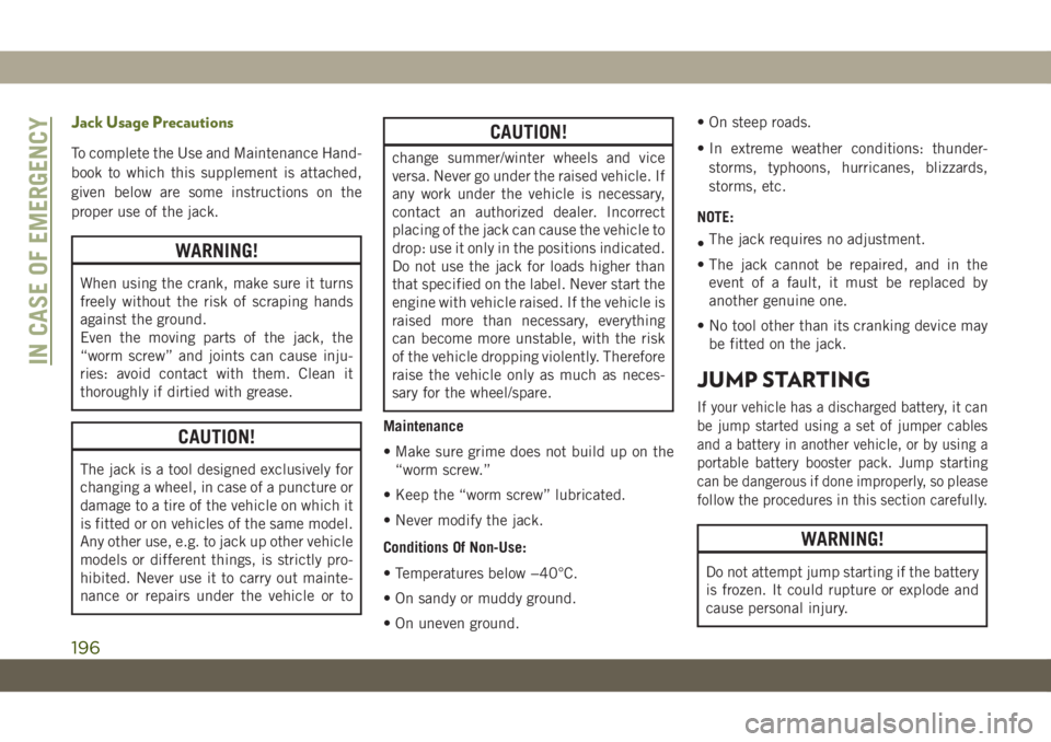
Jack Usage Precautions
To complete the Use and Maintenance Hand-
book to which this supplement is attached,
given below are some instructions on the
proper use of the jack.
WARNING!
When using the crank, make sure it turns
freely without the risk of scraping hands
against the ground.
Even the moving parts of the jack, the
“worm screw” and joints can cause inju-
ries: avoid contact with them. Clean it
thoroughly if dirtied with grease.
CAUTION!
The jack is a tool designed exclusively for
changing a wheel, in case of a puncture or
damage to a tire of the vehicle on which it
is fitted or on vehicles of the same model.
Any other use, e.g. to jack up other vehicle
models or different things, is strictly pro-
hibited. Never use it to carry out mainte-
nance or repairs under the vehicle or to
CAUTION!
change summer/winter wheels and vice
versa. Never go under the raised vehicle. If
any work under the vehicle is necessary,
contact an authorized dealer. Incorrect
placing of the jack can cause the vehicle to
drop: use it only in the positions indicated.
Do not use the jack for loads higher than
that specified on the label. Never start the
engine with vehicle raised. If the vehicle is
raised more than necessary, everything
can become more unstable, with the risk
of the vehicle dropping violently. Therefore
raise the vehicle only as much as neces-
sary for the wheel/spare.
Maintenance
• Make sure grime does not build up on the
“worm screw.”
• Keep the “worm screw” lubricated.
• Never modify the jack.
Conditions Of Non-Use:
• Temperatures below −40°C.
• On sandy or muddy ground.
• On uneven ground.• On steep roads.
• In extreme weather conditions: thunder-
storms, typhoons, hurricanes, blizzards,
storms, etc.
NOTE:
•The jack requires no adjustment.
• The jack cannot be repaired, and in the
event of a fault, it must be replaced by
another genuine one.
• No tool other than its cranking device may
be fitted on the jack.
JUMP STARTING
If your vehicle has a discharged battery, it can
be jump started using a set of jumper cables
and a battery in another vehicle, or by using a
portable battery booster pack. Jump starting
can be dangerous if done improperly, so please
follow the procedures in this section carefully.
WARNING!
Do not attempt jump starting if the battery
is frozen. It could rupture or explode and
cause personal injury.
IN CASE OF EMERGENCY
196
Page 200 of 348
WARNING!
Do not allow vehicles to touch each other
as this could establish a ground connec-
tion and personal injury could result.
Jump Starting Procedure
WARNING!
Failure to follow this jump starting proce-
dure could result in personal injury or
property damage due to battery explosion.
CAUTION!
Failure to follow these procedures could
result in damage to the charging system of
the booster vehicle or the discharged ve-
hicle.
NOTE:
Make sure at all times that unused ends of
jumper cables are not contacting each other
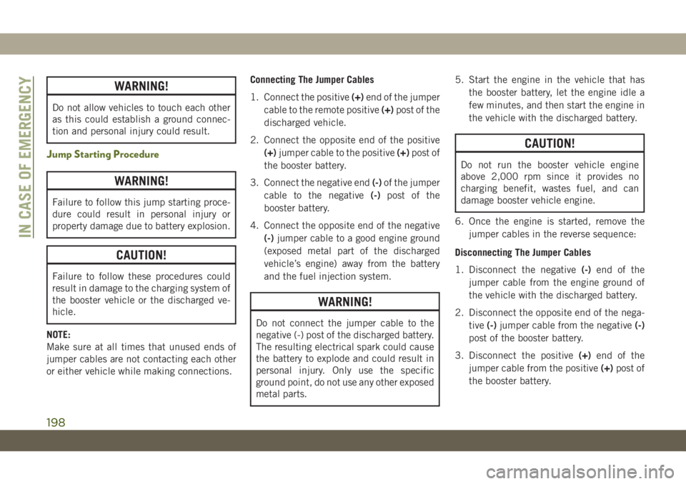
or either vehicle while making connections.Connecting The Jumper Cables
1. Connect the positive(+)end of the jumper
cable to the remote positive(+)post of the
discharged vehicle.
2. Connect the opposite end of the positive
(+)jumper cable to the positive(+)post of
the booster battery.
3. Connect the negative end(-)of the jumper
cable to the negative(-)post of the
booster battery.
4. Connect the opposite end of the negative
(-)jumper cable to a good engine ground
(exposed metal part of the discharged
vehicle’s engine) away from the battery
and the fuel injection system.
WARNING!
Do not connect the jumper cable to the
negative (-) post of the discharged battery.
The resulting electrical spark could cause
the battery to explode and could result in
personal injury. Only use the specific
ground point, do not use any other exposed
metal parts.5. Start the engine in the vehicle that has
the booster battery, let the engine idle a
few minutes, and then start the engine in
the vehicle with the discharged battery.
CAUTION!
Do not run the booster vehicle engine
above 2,000 rpm since it provides no
charging benefit, wastes fuel, and can
damage booster vehicle engine.
6. Once the engine is started, remove the
jumper cables in the reverse sequence:
Disconnecting The Jumper Cables
1. Disconnect the negative(-)end of the
jumper cable from the engine ground of
the vehicle with the discharged battery.
2. Disconnect the opposite end of the nega-
tive(-)jumper cable from the negative(-)
post of the booster battery.
3. Disconnect the positive(+)end of the
jumper cable from the positive(+)post of
the booster battery.
IN CASE OF EMERGENCY
198
Page 202 of 348
MANUAL PARK RELEASE
WARNING!
Always secure your vehicle by fully apply-
ing the parking brake before activating the
Manual Park Release. In addition, you
should be seated in the driver’s seat with
your foot firmly on the brake pedal when
activating the Manual Park Release. Acti-
vating the Manual Park Release will allow
your vehicle to roll away if it is not secured
by the parking brake, or by proper connec-
tion to a tow vehicle. Activating the
Manual Park Release on an unsecured
vehicle could lead to serious injury or
death for those in or around the vehicle.
In order to push or tow the vehicle in cases
where the transmission will not shift out of
PARK (such as a dead battery), a Manual
Park Release is available.
Follow these steps to use the Manual Park
Release:
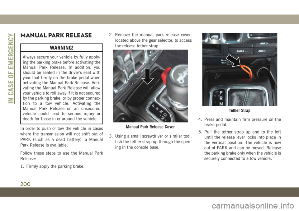
1. Firmly apply the parking brake.2. Remove the manual park release cover,
located above the gear selector, to access
the release tether strap.
3. Using a small screwdriver or similar tool,
fish the tether strap up through the open-
ing in the console base.4. Press and maintain firm pressure on the
brake pedal.
5. Pull the tether strap up and to the left
until the release lever locks into place in
the vertical position. The vehicle is now
out of PARK and can be moved. Release
the parking brake only when the vehicle is
securely connected to a tow vehicle.
Manual Park Release Cover
Tether Strap
IN CASE OF EMERGENCY
200
Page 204 of 348
TOWING A DISABLED
VEHICLE
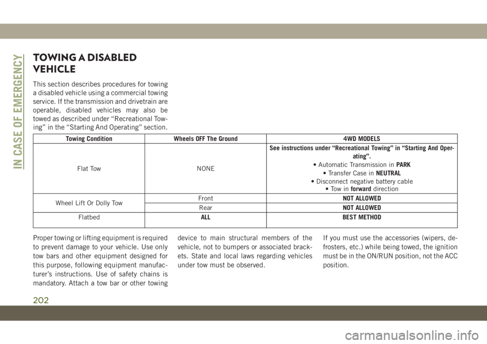
This section describes procedures for towing
a disabled vehicle using a commercial towing
service. If the transmission and drivetrain are
operable, disabled vehicles may also be
towed as described under “Recreational Tow-
ing” in the “Starting And Operating” section.
Towing Condition Wheels OFF The Ground 4WD MODELS
Flat Tow NONESee instructions under “Recreational Towing” in “Starting And Oper-
ating”.
• Automatic Transmission inPARK
• Transfer Case inNEUTRAL
• Disconnect negative battery cable
• Tow inforwarddirection
Wheel Lift Or Dolly TowFrontNOT ALLOWED
RearNOT ALLOWED
FlatbedALL BEST METHOD
Proper towing or lifting equipment is required
to prevent damage to your vehicle. Use only
tow bars and other equipment designed for
this purpose, following equipment manufac-
turer’s instructions. Use of safety chains is
mandatory. Attach a tow bar or other towingdevice to main structural members of the
vehicle, not to bumpers or associated brack-
ets. State and local laws regarding vehicles
under tow must be observed.If you must use the accessories (wipers, de-
frosters, etc.) while being towed, the ignition
must be in the ON/RUN position, not the ACC
position.
IN CASE OF EMERGENCY
202
Page 206 of 348
WARNING!
• Do not use a tow strap with a tow eye.
Tow straps may break or become disen-
gaged, causing serious injury or death.
• Failure to follow proper tow eye usage
may cause components to break result-
ing in serious injury or death.
• The brake and steering power assist sys-
tems will not function while the vehicle
is being towed. You will, therefore, need
to apply more force on the brake pedal
and steering wheel. Do not use flexible
ropes when towing, and avoid jerky
movements. Do not start the engine
while towing the car. Before tightening
the ring, clean the threaded housing
thoroughly. Make sure that the ring is
fully screwed into the housing before
towing the car.
CAUTION!
• The tow eye must only be used for road-
side emergencies. Use with an appropri-
ate device in accordance with highway
code (a rigid bar) to maneuver the ve-
hicle in preparation for transport via a
tow truck.
• The tow eye must not be used to move
the vehicle off the road or where there
are obstacles.
• Do not use the tow eyes for tow truck
hookup or highway towing.
• Do not use the tow eye to free a stuck
vehicle. Refer to the “Freeing A Stuck
Vehicle” section for further information.
• Please refer to the “Towing A Disabled
Vehicle” section for detailed instruc-
tions. Damage to your vehicle may occur
if these guidelines are not followed.NOTE:
• Ensure that the tow eye is properly
mounted.
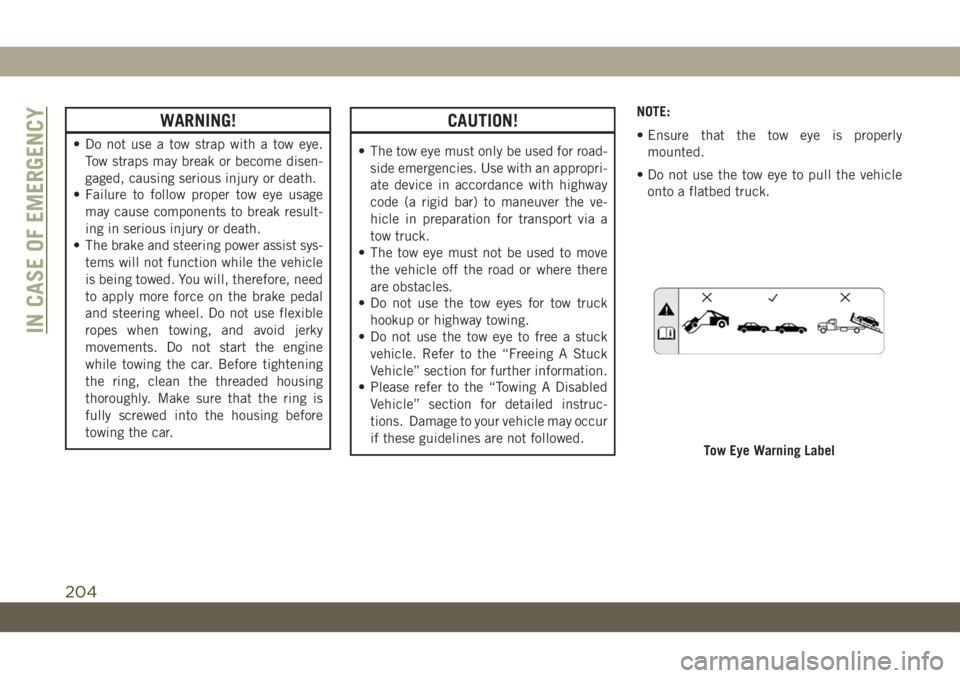
• Do not use the tow eye to pull the vehicle
onto a flatbed truck.
Tow Eye Warning Label
IN CASE OF EMERGENCY
204
Page 223 of 348
Maintenance-Free Battery
Your vehicle is equipped with a maintenance-
free battery. You will never have to add water,
nor is periodic maintenance required.
WARNING!
• Using the battery with low fluid will
irreparably damage the battery and may
cause an explosion.
• When performing any operation on the
battery or near it, always protect your
eyes with special goggles.
• Batteries contain substances which are
very dangerous for the environment. For
battery replacement, contact an autho-
rized dealership.
• Battery fluid is a corrosive acid solution
and can burn or even blind you. Do not
allow battery fluid to contact your eyes,
skin, or clothing. Do not lean over a
battery when attaching clamps. If acid
splashes in eyes or on skin, flush the
area immediately with large amounts of
water. Refer to “Jump Starting Proce-
WARNING!
dure” in “In Case Of Emergency” for
further information.
• Battery gas is flammable and explosive.
Keep flame or sparks away from the
battery. Do not use a booster battery or
any other booster source with an output
greater than 12 Volts. Do not allow cable
clamps to touch each other.
• Battery posts, terminals, and related ac-
cessories contain lead and lead com-
pounds. Wash hands after handling.
CAUTION!
• It is essential when replacing the cables
on the battery that the positive cable is
attached to the positive post and the
negative cable is attached to the nega-
tive post. Battery posts are marked posi-
tive (+) and negative (-) and are identi-
fied on the battery case. Cable clamps
should be tight on the terminal posts
and free of corrosion.
• If a “fast charger” is used while the
battery is in the vehicle, disconnect both
CAUTION!
vehicle battery cables before connecting
the charger to the battery. Do not use a
“fast charger” to provide starting volt-
age.
DEALER SERVICE
An authorized dealer has the qualified service
personnel, special tools, and equipment to
perform all service operations in an expert
manner. Service Manuals are available which
include detailed service information for your
vehicle. Refer to these Service Manuals be-
fore attempting any procedure yourself.
NOTE:
Intentional tampering with emissions control
systems may void your warranty and could
result in civil penalties being assessed
against you.
WARNING!
You can be badly injured working on or
around a motor vehicle. Only do service
221