In case of emergency JEEP WRANGLER UNLIMITED 2018 Owner handbook (in English)
[x] Cancel search | Manufacturer: JEEP, Model Year: 2018, Model line: WRANGLER UNLIMITED, Model: JEEP WRANGLER UNLIMITED 2018Pages: 348, PDF Size: 6.5 MB
Page 7 of 348
GRAPHICAL TABLE OF CONTENTS
GETTING TO KNOW YOUR VEHICLE
GETTING TO KNOW YOUR INSTRUMENT PANEL
SAFETY
STARTING AND OPERATING
IN CASE OF EMERGENCY
SERVICING AND MAINTENANCE
TECHNICAL SPECIFICATIONS
MULTIMEDIA
CUSTOMER ASSISTANCE
INDEX
Page 17 of 348
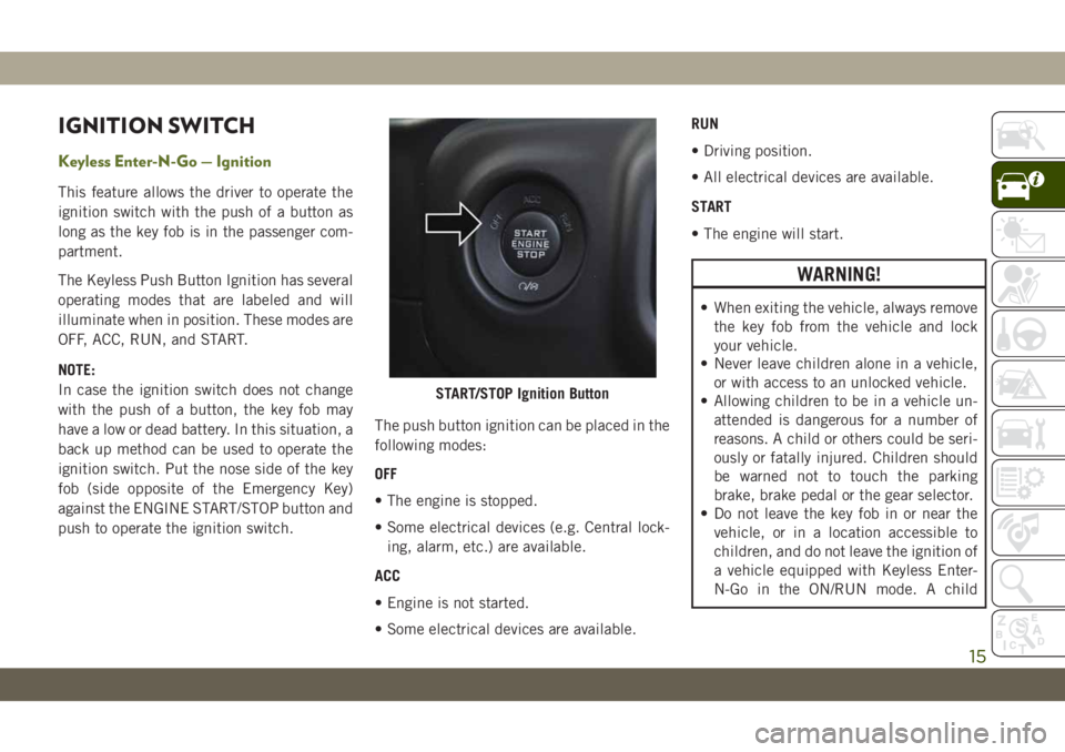
IGNITION SWITCH
Keyless Enter-N-Go — Ignition
This feature allows the driver to operate the
ignition switch with the push of a button as
long as the key fob is in the passenger com-
partment.
The Keyless Push Button Ignition has several
operating modes that are labeled and will
illuminate when in position. These modes are
OFF, ACC, RUN, and START.
NOTE:
In case the ignition switch does not change
with the push of a button, the key fob may
have a low or dead battery. In this situation, a
back up method can be used to operate the
ignition switch. Put the nose side of the key
fob (side opposite of the Emergency Key)
against the ENGINE START/STOP button and
push to operate the ignition switch.The push button ignition can be placed in the
following modes:
OFF
• The engine is stopped.
• Some electrical devices (e.g. Central lock-
ing, alarm, etc.) are available.
ACC
• Engine is not started.
• Some electrical devices are available.RUN
• Driving position.
• All electrical devices are available.
START
• The engine will start.
WARNING!
• When exiting the vehicle, always remove
the key fob from the vehicle and lock
your vehicle.
• Never leave children alone in a vehicle,
or with access to an unlocked vehicle.
• Allowing children to be in a vehicle un-
attended is dangerous for a number of
reasons. A child or others could be seri-
ously or fatally injured. Children should
be warned not to touch the parking
brake, brake pedal or the gear selector.
• Do not leave the key fob in or near the
vehicle, or in a location accessible to
children, and do not leave the ignition of
a vehicle equipped with Keyless Enter-
N-Go in the ON/RUN mode. A child
START/STOP Ignition Button
15
Page 71 of 348
into NEUTRAL and idle the vehicle. If the
temperature reading does not return to nor-
mal, turn the engine off immediately and call
for service.
Refer to “If Your Engine Overheats” in “In
Case Of Emergency” for further information.
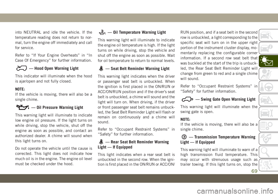
— Hood Open Warning Light
This indicator will illuminate when the hood
is ajar/open and not fully closed.
NOTE:
If the vehicle is moving, there will also be a
single chime.
— Oil Pressure Warning Light
This warning light will illuminate to indicate
low engine oil pressure. If the light turns on
while driving, stop the vehicle, shut off the
engine as soon as possible, and contact an
authorized dealer. A chime will sound when
this light turns on.
Do not operate the vehicle until the cause is
corrected. This light does not indicate how
much oil is in the engine. The engine oil level
must be checked under the hood.
— Oil Temperature Warning Light
This warning light will illuminate to indicate
the engine oil temperature is high. If the light
turns on while driving, stop the vehicle and
shut off the engine as soon as possible. Wait
for oil temperature to return to normal levels.
— Seat Belt Reminder Warning Light
This warning light indicates when the driver
or passenger seat belt is unbuckled. When
the ignition is first placed in the ON/RUN or
ACC/ON/RUN position and if the driver’s seat
belt is unbuckled, a chime will sound and the
light will turn on. When driving, if the driver
or front passenger seat belt remains unbuck-
led, the Seat Belt Reminder Light will flash or
remain on continuously and a chime will
sound.
Refer to “Occupant Restraint Systems” in
“Safety” for further information.
— Rear Seat Belt Reminder Warning
Light — If Equipped
This light indicates when a rear seat belt is
unbuckled in the second row. When the igni-
tion is first placed in the ON/RUN or ACC/ON/RUN position, and if a seat belt in the second
row is unbuckled, a light corresponding to the
specific seat will turn on in the upper right
portion of the instrument cluster display, mo-
mentarily replacing the configurable corner
information. If a second row seat belt that
was buckled at the start of the trip is unbuck-
led, the Rear Seat Belt Reminder Light will
change from green to red and a single chime
will sound.
Refer to “Occupant Restraint Systems” in
“Safety” for further information.
— Swing Gate Open Warning Light
This warning light will illuminate when the
swing gate is open.
NOTE:
If the vehicle is moving, there will also be a
single chime.
— Transmission Temperature Warning
Light — If Equipped
This warning light will illuminate to warn of a
high transmission fluid temperature. This
may occur with strenuous usage such as
trailer towing. If this light turns on, stop the
69
Page 177 of 348
IN CASE OF EMERGENCY
HAZARD WARNING FLASHERS .176
BULB REPLACEMENT........176
Replacement Bulbs............176
Bulb Replacement.............178
FUSES...................180
General Information.............181
Power Distribution Center (PDC).....181
JACKING AND TIRE CHANGING. .189
Jack Location................190
Spare Tire Removal.............190Preparations For Jacking.........191
Jacking Instructions............191
Road Tire Installation............194
Declaration Of Conformance.......194
Jack Usage Precautions..........196
JUMP STARTING............196
Preparations For Jump Start........197
Jump Starting Procedure..........198
IF YOUR ENGINE OVERHEATS . .199
MANUAL PARK RELEASE.....200FREEING A STUCK VEHICLE . . .201
TOWING A DISABLED VEHICLE.202
Without The Key Fob............203
Four–Wheel Drive Models.........203
Tow Eye Usage................203
ENHANCED ACCIDENT RESPONSE
SYSTEM (EARS)............205
EVENT DATA RECORDER
(EDR)....................205
IN CASE OF EMERGENCY
175
Page 178 of 348
HAZARD WARNING
FLASHERS
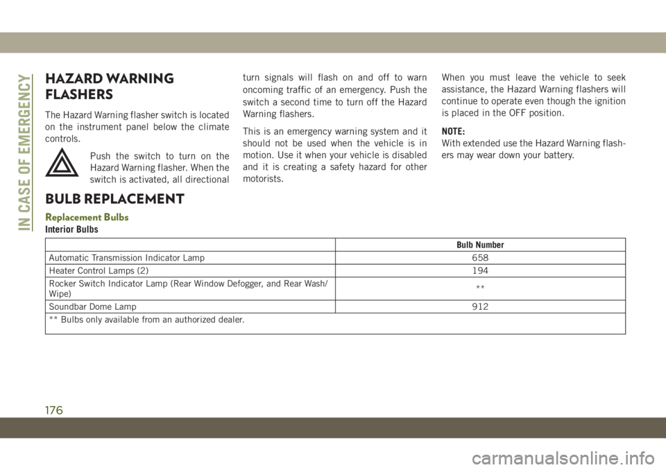
The Hazard Warning flasher switch is located
on the instrument panel below the climate
controls.
Push the switch to turn on the
Hazard Warning flasher. When the
switch is activated, all directionalturn signals will flash on and off to warn
oncoming traffic of an emergency. Push the
switch a second time to turn off the Hazard
Warning flashers.
This is an emergency warning system and it
should not be used when the vehicle is in
motion. Use it when your vehicle is disabled
and it is creating a safety hazard for other
motorists.When you must leave the vehicle to seek
assistance, the Hazard Warning flashers will
continue to operate even though the ignition
is placed in the OFF position.
NOTE:
With extended use the Hazard Warning flash-
ers may wear down your battery.
BULB REPLACEMENT
Replacement Bulbs
Interior Bulbs
Bulb Number
Automatic Transmission Indicator Lamp 658
Heater Control Lamps (2)194
Rocker Switch Indicator Lamp (Rear Window Defogger, and Rear Wash/
Wipe)**
Soundbar Dome Lamp912
** Bulbs only available from an authorized dealer.
IN CASE OF EMERGENCY
176
Page 180 of 348
Bulb Replacement
NOTE:
Lens fogging can occur under certain atmo-
spheric conditions. This will usually clear as
atmospheric conditions change to allow the
condensation to change back into a vapor.
Turning the lamps on will usually accelerate
the clearing process.
Halogen Headlamps
NOTE:
We advise referring to an authorized dealer
for service.
1. Open hood and support using prop rod.
2. Remove the front grille. Turn the retainers
along the top 1/4 turn counterclockwise
and remove.
3. Pull the bottom of the grille away starting
at one side and working toward the other.
4. Remove the three screws holding the
headlamp to the vehicle.
5. Remove lamp from the vehicle.
6. Remove the lamp from the collar.7. Grasp the bulb and turn 1/4 turn
counterclockwise.
8. Pull the bulb from the housing.
9. Push connector locking tab to the unlock
position.
10. Remove connector from bulb.
11. Push connector onto new bulb base, and
push the connector locking tab to the
lock position.CAUTION!
Do not touch the new bulb with your fin-
gers. Oil contamination will severely
shorten bulb life. If the bulb comes in
contact with any oily surface, clean the
bulb with rubbing alcohol.
12. Reinstall bulb housing. Rotate the bulb
1/4 turn clockwise.
Front Park/Turn Signal
NOTE:
We advise referring to an authorized dealer
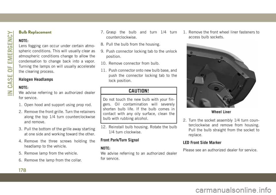
for service.1. Remove the front wheel liner fasteners to
access bulb sockets.
2. Turn the socket assembly 1/4 turn coun-
terclockwise and remove from housing.
Pull the bulb straight from the socket to
replace.
LED Front Side Marker
Please see an authorized dealer for service.
Wheel Liner
IN CASE OF EMERGENCY
178
Page 182 of 348
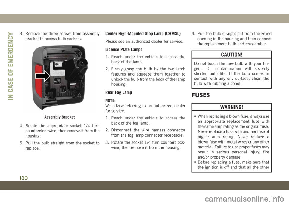
3. Remove the three screws from assembly
bracket to access bulb sockets.
4. Rotate the appropriate socket 1/4 turn
counterclockwise, then remove it from the
housing.
5. Pull the bulb straight from the socket to
replace.Center High-Mounted Stop Lamp (CHMSL)
Please see an authorized dealer for service.
License Plate Lamps
1. Reach under the vehicle to access the
back of the lamp.
2. Firmly grasp the bulb by the two latch
features and squeeze them together to
unlock the bulb from the back of the lamp
housing.
Rear Fog Lamp
NOTE:
We advise referring to an authorized dealer
for service.
1. Reach under the vehicle to access the
back of the fog lamp.
2. Disconnect the wire harness connector
from the fog lamp connector receptacle.
3. Rotate the socket 1/4 turn counterclock-
wise, then remove it from the housing.4. Pull the bulb straight out from the keyed
opening in the housing and then connect
the replacement bulb and reassemble.
CAUTION!
Do not touch the new bulb with your fin-
gers. Oil contamination will severely
shorten bulb life. If the bulb comes in
contact with any oily surface, clean the
bulb with rubbing alcohol.
FUSES
WARNING!
• When replacing a blown fuse, always use
an appropriate replacement fuse with
the same amp rating as the original fuse.
Never replace a fuse with another fuse of
higher amp rating. Never replace a
blown fuse with metal wires or any other
material. Failure to use proper fuses may
result in serious personal injury, fire
and/or property damage.
• Before replacing a fuse, make sure that
the ignition is off and that all the otherAssembly Bracket
IN CASE OF EMERGENCY
180
Page 184 of 348
Cavity Cartridge Fuse Micro Fuse Description
F05 – 5 Amp Tan Security Gateway
(*)
F06 – – Spare
F07 – 15 Amp Blue Low Temp Radiator Cooling Pump (LTR) — If Equipped
(*)
F08 – 15 Amp Blue Trans Control Module TCM-8HP CYGNUS
(*)
F09 – – Spare
F10 – 15 Amp Blue Key Ignition Node (KIN)/Radio Frequency Hub(RF HUB)/
Electric Steering Column Lock (ESCL)
(*)
F11 – 10 Amp Red UCI Port (USB & AUX)
F12 – 25 Amp Clear HIFI Amplifier
F13 – – Spare
F14 – – Spare
F15 – 15 Amp Blue Instrument Panel Cluster (IPC)/Switch Bank-Heavy Duty
Electrical Pkg (SWITCH BANK-HD ELEC)
(*)
F16 – – Spare
F17 – – Spare
F18 – 10 Amp Red Air Conditioning Clutch (AC CLUTCH)
(*)
F19 – – Spare
F20 30 Amp Pink – Central Body Controller (CBC) 1-INTERIOR LIGHTS
F21 – 20 Amp Yellow REAR WIPER
IN CASE OF EMERGENCY
182
Page 186 of 348
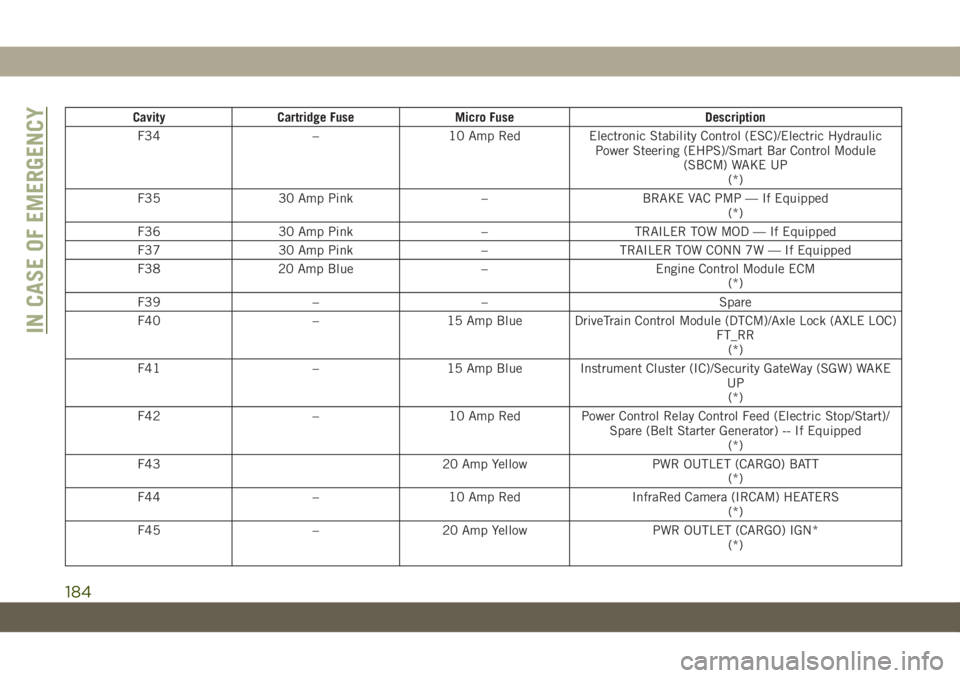
Cavity Cartridge Fuse Micro Fuse Description
F34 – 10 Amp Red Electronic Stability Control (ESC)/Electric Hydraulic
Power Steering (EHPS)/Smart Bar Control Module
(SBCM) WAKE UP
(*)
F35 30 Amp Pink – BRAKE VAC PMP — If Equipped
(*)
F36 30 Amp Pink – TRAILER TOW MOD — If Equipped
F37 30 Amp Pink – TRAILER TOW CONN 7W — If Equipped
F38 20 Amp Blue – Engine Control Module ECM
(*)
F39 – – Spare
F40 – 15 Amp Blue DriveTrain Control Module (DTCM)/Axle Lock (AXLE LOC)
FT_RR
(*)
F41 – 15 Amp Blue Instrument Cluster (IC)/Security GateWay (SGW) WAKE
UP
(*)
F42 – 10 Amp Red Power Control Relay Control Feed (Electric Stop/Start)/
Spare (Belt Starter Generator) -- If Equipped
(*)
F43 20 Amp Yellow PWR OUTLET (CARGO) BATT
(*)
F44 – 10 Amp Red InfraRed Camera (IRCAM) HEATERS
(*)
F45 – 20 Amp Yellow PWR OUTLET (CARGO) IGN*
(*)
IN CASE OF EMERGENCY
184
Page 188 of 348
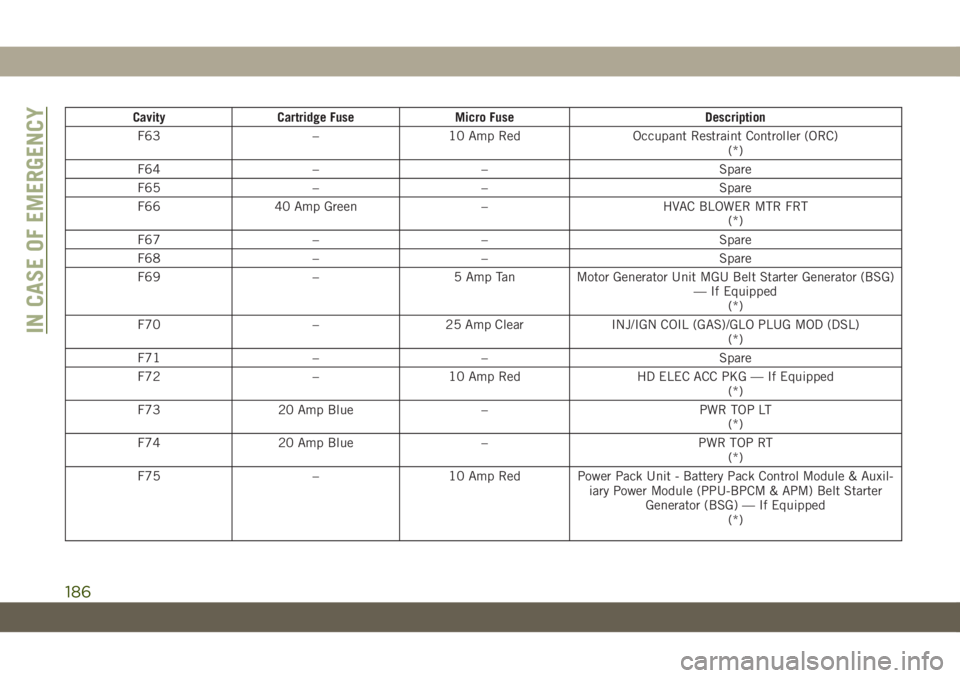
Cavity Cartridge Fuse Micro Fuse Description
F63 – 10 Amp Red Occupant Restraint Controller (ORC)
(*)
F64 – – Spare
F65 – – Spare
F66 40 Amp Green – HVAC BLOWER MTR FRT
(*)
F67 – – Spare
F68 – – Spare
F69 – 5 Amp Tan Motor Generator Unit MGU Belt Starter Generator (BSG)
— If Equipped
(*)
F70 – 25 Amp Clear INJ/IGN COIL (GAS)/GLO PLUG MOD (DSL)
(*)
F71 – – Spare
F72 – 10 Amp Red HD ELEC ACC PKG — If Equipped
(*)
F73 20 Amp Blue – PWR TOP LT
(*)
F74 20 Amp Blue – PWR TOP RT
(*)
F75 – 10 Amp Red Power Pack Unit - Battery Pack Control Module & Auxil-
iary Power Module (PPU-BPCM & APM) Belt Starter
Generator (BSG) — If Equipped
(*)
IN CASE OF EMERGENCY
186