steering JEEP WRANGLER UNLIMITED 2018 Owner handbook (in English)
[x] Cancel search | Manufacturer: JEEP, Model Year: 2018, Model line: WRANGLER UNLIMITED, Model: JEEP WRANGLER UNLIMITED 2018Pages: 348, PDF Size: 6.5 MB
Page 117 of 348

Following the actions listed in the table above
will DISABLE (OFF) the Passenger Advanced
Front Air Bag. The Passenger Air Bag DIS-
ABLE (OFF) Indicator light on the overhead
sports bar will illuminate
to show that the
Passenger Advanced Front Air Bag will not
deploy during a collision.
ENABLING (ON) The Passenger Advanced Front
Air Bag
Access the instrument cluster display main
menu located in the instrument cluster by
pushing the Up or Down arrow button located
on the steering wheel, then complete the
following actions:
Action Information
Scroll Up or Down to
“Vehicle Set-Up”
Press the “OK” on
the vehicle steering
wheel to enter “Ve-
hicle Settings”
Scroll Up or Down
using the arrow but-
tons on the steering
wheel to select “Se-
curity”
Action Information
Press the “OK” but-
ton on the steering
wheel to select “Se-
curity”
Press the “OK” but-
ton on the steering
wheel to select “Pas-
senger AIRBAG”
Scroll Up or Down to
Passenger AIRBAG
ON “
ON”NOTE:
If the Passenger Ad-
vanced Front Air Bag
was previously DIS-
ABLED (OFF) it will
default to OFF and
user will have to
scroll down to select
ON.
Press the “OK” but-
ton on the steering
wheel to select Pas-
senger AIRBAG ON “
ON”
Action Information
Press the “OK” but-
ton on the steering
wheel to select “Yes”NOTE:
If this step is not
completed within
1 minute this option
will timeout and this
process will have to
be repeated.
A single chime will
sound with the Pas-
senger AIRBAG ON
indicator light
illuminated for 4 to
5 seconds confirming
the enabling of the
Passenger Advanced
Front Air Bag.
The Passenger AIR-
BAG ON
indica-
tor light will remain
continuously illumi-
nated telling the
driver and front pas-
senger that the Pas-
senger Advanced
Front Air Bag is EN-
ABLED (ON).
115
Page 120 of 348

WARNING!
inflate, even if they are in an infant or
child restraint.
• Seat belts (and child restraints where
appropriate) are necessary for your pro-
tection in all collisions. They also help
keep you in position, away from an in-
flating Side Air Bag. To get the best
protection from the Side Air Bags, occu-
pants must wear their seat belts properly
and sit upright with their backs against
the seats. Children must be properly
restrained in a child restraint or booster
seat that is appropriate for the size of the
child.
WARNING!
• Side Air Bags need room to inflate. Do
not lean against the door or window. Sit
upright in the center of the seat.
• Being too close to the Side Air Bags
during deployment could cause you to
be severely injured or killed.
• Relying on the Side Air Bags alone could
lead to more severe injuries in a colli-
WARNING!
sion. The Side Air Bags work with your
seat belt to restrain you properly. In
some collisions, Side Air Bags won’t
deploy at all. Always wear your seat belt
even though you have Side Air Bags.
NOTE:
Air bag covers may not be obvious in the
interior trim, but they will open during air bag
deployment.
Air Bag System Components
NOTE:
The Occupant Restraint Controller (ORC)
monitors the internal circuits and intercon-
necting wiring associated with electrical Air
Bag System Components listed below:
• Occupant Restraint Controller (ORC)
• Air Bag Warning Light
• Steering Wheel and Column
• Instrument Panel
• Knee Impact Bolsters
• Driver and Front Passenger Air Bags• Seat Belt Buckle Switch
• Supplemental Side Air Bags
• Front and Side Impact Sensors
• Seat Belt Pretensioners
If A Deployment Occurs
The front air bags are designed to deflate
immediately after deployment.
NOTE:
Front and/or side air bags will not deploy in
all collisions. This does not mean something
is wrong with the air bag system.
If you do have a collision which deploys the
air bags, any or all of the following may occur:
• The air bag material may sometimes cause
abrasions and/or skin reddening to the oc-
cupants as the air bags deploy and unfold.
The abrasions are similar to friction rope
burns or those you might get sliding along a
carpet or gymnasium floor. They are not
caused by contact with chemicals. They are
not permanent and normally heal quickly.
However, if you haven’t healed significantly
within a few days, or if you have any blis-
tering, see your doctor immediately.
SAFETY
118
Page 121 of 348
• As the air bags deflate, you may see some
smoke-like particles. The particles are a
normal by-product of the process that gen-
erates the non-toxic gas used for air bag
inflation. These airborne particles may irri-
tate the skin, eyes, nose, or throat. If you
have skin or eye irritation, rinse the area
with cool water. For nose or throat irritation,
move to fresh air. If the irritation continues,
see your doctor. If these particles settle on
your clothing, follow the garment manufac-
turer’s instructions for cleaning.
Do not drive your vehicle after the air bags
have deployed. If you are involved in another
collision, the air bags will not be in place to
protect you.
WARNING!
Deployed air bags and seat belt preten-
sioners cannot protect you in another col-
lision. Have the air bags, seat belt preten-
sioners, and the seat belt retractor
assemblies replaced by an authorized
dealer immediately. Also, have the Occu-
pant Restraint Controller System serviced
as well.NOTE:
• Air bag covers may not be obvious in the
interior trim, but they will open during air
bag deployment.
• After any collision, the vehicle should be
taken to an authorized dealer immediately.
Enhanced Accident Response System
In the event of an impact, if the communica-
tion network remains intact, and the power
remains intact, depending on the nature of
the event, the ORC will determine whether to
have the Enhanced Accident Response Sys-
tem perform the following functions:
• Cut off fuel to the engine (If Equipped)
• Cut off battery power to the electric motor
(If Equipped)
• Flash hazard lights as long as the battery
has power
• Turn on the interior lights, which remain on
as long as the battery has power or for 15
minutes from the intervention of the En-
hanced Accident Response System.
• Unlock the power door locks.Your vehicle may also be designed to perform
any of these other functions in response to
the Enhanced Accident Response System:
• Turn off the Fuel Filter Heater, Turn off the
HVAC Blower Motor, Close the HVAC Circu-
lation Door
• Cut off battery power to the:
– Engine
– Electric Motor (if equipped)
– Electric power steering
– Brake booster
– Electric park brake
– Automatic transmission gear selector
– Horn
– Front wiper
– Headlamp washer pump
NOTE:
After an accident, remember to cycle the
ignition to the STOP (OFF/LOCK) position
and remove the key from the ignition switch
to avoid draining the battery. Carefully check
the vehicle for fuel leaks in the engine com-
partment and on the ground near the engine
compartment and fuel tank before resetting
the system and starting the engine. If there
are no fuel leaks or damage to the vehicle
119
Page 122 of 348

electrical devices (e.g. headlights) after an
accident, reset the system by following the
procedure described below. If you have any
doubt, contact an authorized dealer.
Enhanced Accident Response System Reset
Procedure
In order to reset the Enhanced Accident Re-
sponse System functions after an event, the
ignition switch must be changed from igni-
tion START or ON/RUN to ignition OFF. Care-
fully check the vehicle for fuel leaks in the
engine compartment and on the ground near
the engine compartment and fuel tank before
resetting the system and starting the engine.
Maintaining Your Air Bag System
WARNING!
• Modifications to any part of the air bag
system could cause it to fail when you
need it. You could be injured if the air
bag system is not there to protect you.
Do not modify the components or wiring,
including adding any kind of badges or
stickers to the steering wheel hub trim
WARNING!
cover or the upper passenger side of the
instrument panel. Do not modify the
front bumper, vehicle body structure, or
add aftermarket side steps or running
boards.
• It is dangerous to try to repair any part of
the air bag system yourself. Be sure to
tell anyone who works on your vehicle
that it has an air bag system.
• Do not attempt to modify any part of your
air bag system. The air bag may inflate
accidentally or may not function prop-
erly if modifications are made. Take your
vehicle to an authorized dealer for any
air bag system service. If your seat, in-
cluding your trim cover and cushion,
needs to be serviced in any way (includ-
ing removal or loosening/tightening of
seat attachment bolts), take the vehicle
to an authorized dealer. Only manufac-
turer approved seat accessories may be
used. If it is necessary to modify the air
bag system for persons with disabilities,
contact an authorized dealer.
Event Data Recorder (EDR)
This vehicle is equipped with an event data
recorder (EDR). The main purpose of an EDR
is to record, in certain crash or near crash-
like situations, such as an air bag deployment
or hitting a road obstacle, data that will assist
in understanding how a vehicle’s systems
performed. The EDR is designed to record
data related to vehicle dynamics and safety
systems for a short period of time, typically
30 seconds or less. The EDR in this vehicle is
designed to record such data as:
• How various systems in your vehicle were
operating;
• Whether or not the driver and passenger
safety belts were buckled/fastened;
• How far (if at all) the driver was depressing
the accelerator and/or brake pedal; and,
• How fast the vehicle was traveling.
These data can help provide a better under-
standing of the circumstances in which
crashes and injuries occur.
SAFETY
120
Page 158 of 348
Axle Lock (Tru-Lok) — Rubicon Models
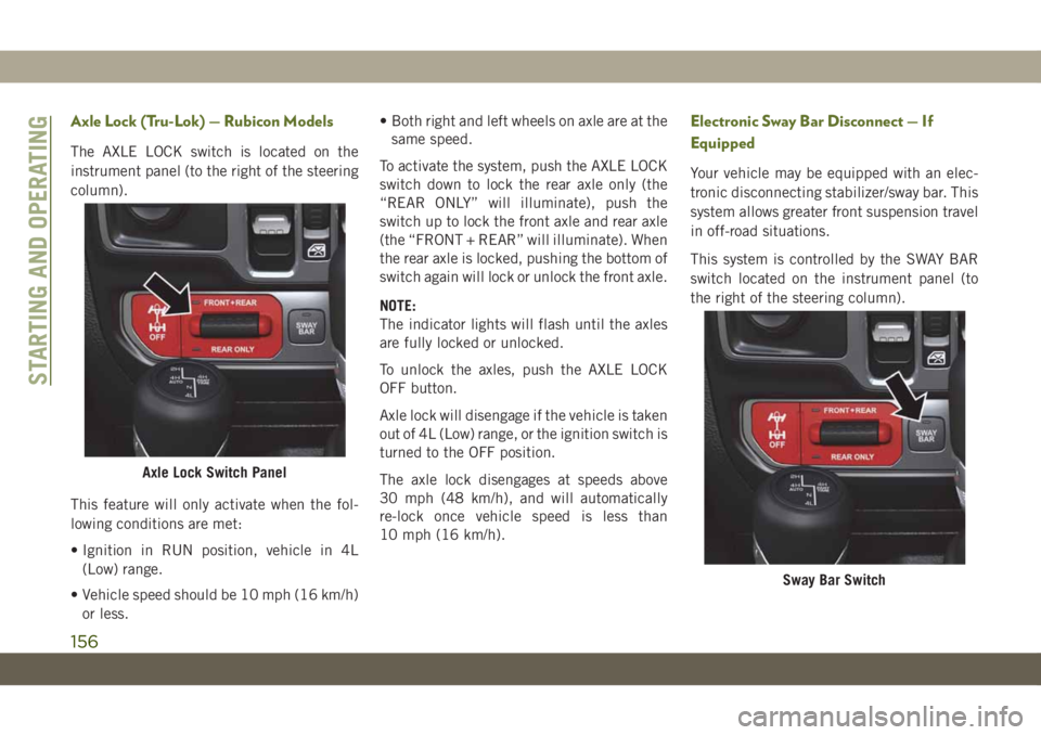
The AXLE LOCK switch is located on the
instrument panel (to the right of the steering
column).
This feature will only activate when the fol-
lowing conditions are met:
• Ignition in RUN position, vehicle in 4L
(Low) range.
• Vehicle speed should be 10 mph (16 km/h)
or less.• Both right and left wheels on axle are at the
same speed.
To activate the system, push the AXLE LOCK
switch down to lock the rear axle only (the
“REAR ONLY” will illuminate), push the
switch up to lock the front axle and rear axle
(the “FRONT + REAR” will illuminate). When
the rear axle is locked, pushing the bottom of
switch again will lock or unlock the front axle.
NOTE:
The indicator lights will flash until the axles
are fully locked or unlocked.
To unlock the axles, push the AXLE LOCK
OFF button.
Axle lock will disengage if the vehicle is taken
out of 4L (Low) range, or the ignition switch is
turned to the OFF position.
The axle lock disengages at speeds above
30 mph (48 km/h), and will automatically
re-lock once vehicle speed is less than
10 mph (16 km/h).
Electronic Sway Bar Disconnect — If
Equipped
Your vehicle may be equipped with an elec-
tronic disconnecting stabilizer/sway bar. This
system allows greater front suspension travel
in off-road situations.
This system is controlled by the SWAY BAR
switch located on the instrument panel (to
the right of the steering column).
Axle Lock Switch Panel
Sway Bar Switch
STARTING AND OPERATING
156
Page 161 of 348
Other Factors Which Can Inhibit Autostop In-
clude:
• Accelerator pedal input.
• Vehicle speed threshold not achieved from
previous auto-stop.
• Steering angle beyond threshold. (ESS
Models Only)
• ACC is on and speed is set.
• Vehicle is at high altitude.
• System fault present.
It may be possible for the vehicle to be driven
several times without the STOP/START sys-
tem going into a STOP/START READY state
under more extreme conditions of the items
listed above.
To Start The Engine While In Autostop
Mode
While in a forward gear, the engine will start
when the brake pedal is released or the
throttle pedal is depressed. The transmission
will automatically re-engage upon engine re-
start.Conditions That Will Cause The Engine To Start
Automatically While In Autostop Mode:
• The transmission selector is moved out of
DRIVE.
• To maintain cabin temperature comfort.
• Actual cabin temperature is significantly
different than temperature set on Auto
HVAC.
• HVAC is set to full defrost mode.
• HVAC system temperature or fan speed is
manually adjusted.
• Battery voltage drops too low.
• Low brake vacuum (e.g. after several brake
pedal applications).
• STOP/START OFF switch is pushed.
• A STOP/START system error occurs.
• STOP/START AUTO STOP ACTIVE time ex-
ceeds 5 minutes.
• 4WD system is put into 4LO or Neutral
mode.
• Steering wheel is turned beyond threshold.
(ESS Models Only)
To Manually Turn Off The Stop/Start
System
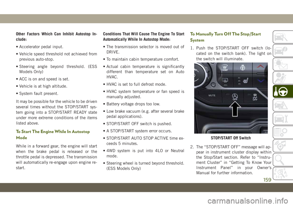
1. Push the STOP/START OFF switch (lo-
cated on the switch bank). The light on
the switch will illuminate.
2. The “STOP/START OFF” message will ap-
pear in instrument cluster display within
the Stop/Start section. Refer to “Instru-
ment Cluster” in “Getting To Know Your
Instrument Panel” in your Owner’s
Manual for further information.
STOP/START Off Switch
159
Page 162 of 348
3. At the next vehicle stop (after turning off
the STOP/START system), the engine will
not be stopped.
4. The STOP/START system will reset itself
back to an ON condition every time the
ignition is turned off and back on.
To Manually Turn On The Stop/Start
System
Push the STOP/START OFF switch (located
on the switch bank). The light on the switch
will turn off.
For complete details on the Stop/Start Sys-
tem refer to the “Stop/Start System” in the
“Starting And Operating” section located in
your Owner’s Manual for further information.
System Malfunction
If there is a malfunction in the STOP/START
system, the system will not shut down the
engine. A “SERVICE STOP/START SYSTEM”
message will appear in the instrument cluster
display. Refer to “Instrument Cluster Dis-
play“ in “Getting to Know Your Instrument
Panel” for further information.
If the “SERVICE STOP/START SYSTEM”
message appears in the instrument cluster
display, have the system checked by an au-
thorized dealer.
SPEED CONTROL
When engaged, the Speed Control takes over
accelerator operations at speeds greater than
20 mph (32 km/h).
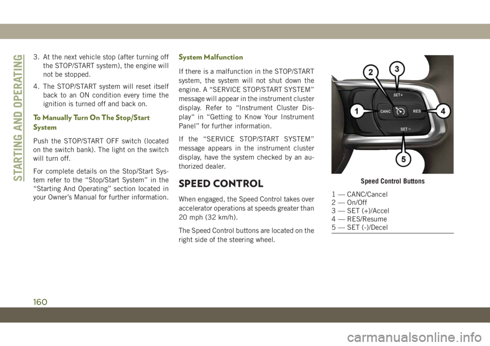
The Speed Control buttons are located on the
right side of the steering wheel.
Speed Control Buttons
1 — CANC/Cancel
2 — On/Off
3 — SET (+)/Accel
4 — RES/Resume
5 — SET (-)/Decel
STARTING AND OPERATING
160
Page 167 of 348
PARKVIEW REAR BACK UP
CAMERA — IF EQUIPPED
The ParkView Rear Back Up Camera allows
you to see an on-screen image of the rear
surroundings of your vehicle whenever the
gear selector is put into REVERSE. The image
will be displayed in the touchscreen display
along with a caution note to “check entire
surroundings” across the top of the screen.
After five seconds this note will disappear.
The ParkView camera is located on the rear of
the vehicle in the center of the spare tire.
Manual Activation Of The Rear View Camera
1. Press the “Controls” button located on
the bottom of the Uconnect display.
2. Press the “Backup Camera” button to
turn the Rear View Camera system on.
NOTE:
The ParkView Rear Back Up Camera has
programmable modes of operation that may
be selected through the Uconnect System.
Refer to “Uconnect Settings” in “Multime-
dia” in your Owner’s Manual for further infor-
mation.When the vehicle is shifted out of REVERSE
(with camera delay turned off), the rear cam-
era mode is exited and the previous screen
appears again. When the vehicle is shifted
out of REVERSE (with camera delay turned
on), the camera image will continue to be
displayed for up to ten seconds after shifting
out of REVERSE unless the vehicle speed
exceeds 8 mph (13 km/h), the vehicle is
shifted into PARK, the vehicle’s ignition is
cycled to the OFF position, or the user
presses image defeat [X] to exit out of the
camera video display.
NOTE:
• If the vehicle speed remains below 8 mph
(13 km/h), the Rear View Camera image will
be displayed continuously until deactivated
via the touchscreen button “X”, the vehicle
is shifted into PARK, or the ignition is
placed in the OFF position.
• The touchscreen button “X” to disable dis-
play of the camera image is made available
ONLY when the vehicle is not in REVERSE.
When enabled, active guide lines are overlaid
on the image to illustrate the width of the
vehicle and its projected backup path basedon the steering wheel position. A dashed
center line overlay indicates the center of the
vehicle to assist with parking or aligning to a
hitch/receiver.
When enabled, fixed guide lines are overlaid
on the image to illustrate the width of the
vehicle.
Different colored zones indicate the distance
to the rear of the vehicle.
WARNING!
Drivers must be careful when backing up
even when using the ParkView Rear Back
Up Camera. Always check carefully behind
your vehicle, and be sure to check for
pedestrians, animals, other vehicles, ob-
structions, or blind spots before backing
up. You are responsible for the safety of
your surroundings and must continue to
pay attention while backing up. Failure to
do so can result in serious injury or death.
165
Page 183 of 348
WARNING!
services are switched off and/or disen-
gaged.
• If the replaced fuse blows again, contact
an authorized dealer.
• If a general protection fuse for safety
systems (air bag system, braking sys-
tem), power unit systems (engine sys-
tem, gearbox system) or steering system
blows, contact an authorized dealer.
CAUTION!
If it is necessary to wash the engine com-
partment, take care not to directly hit the
CAUTION!
fuse box, and the windshield wiper motors
with water.
General Information
The fuses protect electrical systems against
excessive current.
When a device does not work, you must check
the fuse element inside the blade fuse for a
break/melt.
Also, please be aware that when using power
outlets for extended periods of time with the
engine off may result in vehicle battery dis-
charge.
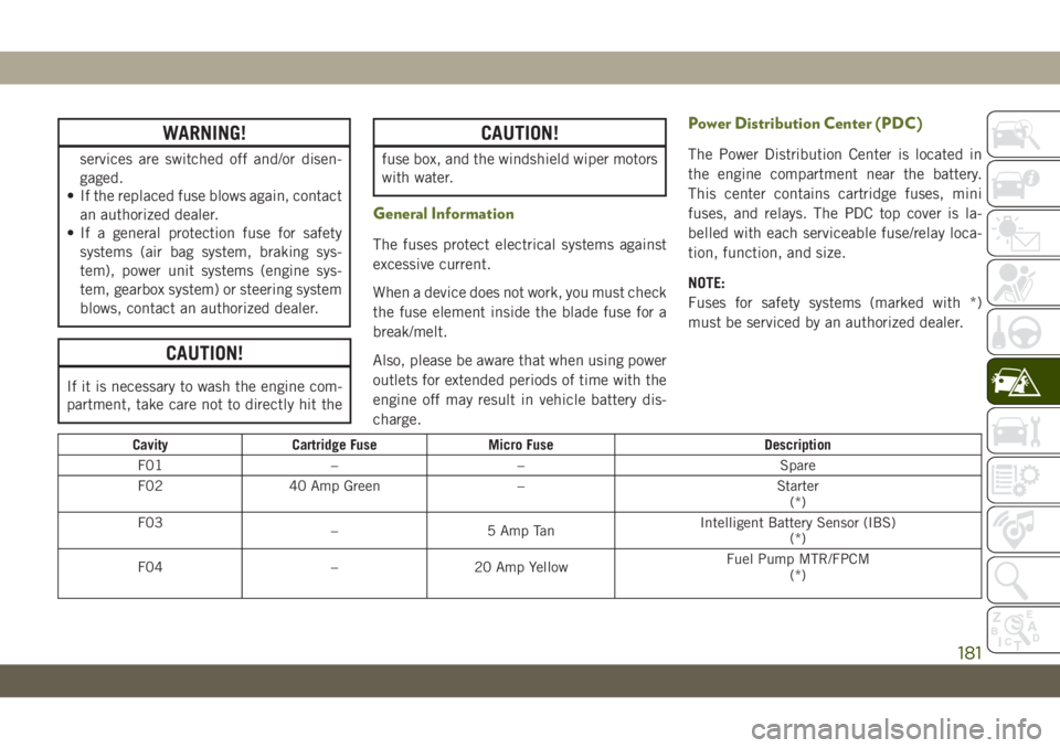
Power Distribution Center (PDC)
The Power Distribution Center is located in
the engine compartment near the battery.
This center contains cartridge fuses, mini
fuses, and relays. The PDC top cover is la-
belled with each serviceable fuse/relay loca-
tion, function, and size.
NOTE:
Fuses for safety systems (marked with *)
must be serviced by an authorized dealer.
Cavity Cartridge Fuse Micro Fuse Description
F01 – – Spare
F02 40 Amp Green – Starter
(*)
F03
– 5 Amp TanIntelligent Battery Sensor (IBS)
(*)
F04 – 20 Amp YellowFuel Pump MTR/FPCM
(*)
181
Page 184 of 348
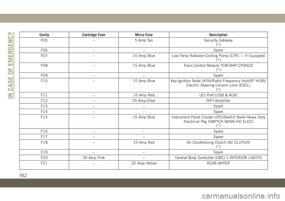
Cavity Cartridge Fuse Micro Fuse Description
F05 – 5 Amp Tan Security Gateway
(*)
F06 – – Spare
F07 – 15 Amp Blue Low Temp Radiator Cooling Pump (LTR) — If Equipped
(*)
F08 – 15 Amp Blue Trans Control Module TCM-8HP CYGNUS
(*)
F09 – – Spare
F10 – 15 Amp Blue Key Ignition Node (KIN)/Radio Frequency Hub(RF HUB)/
Electric Steering Column Lock (ESCL)
(*)
F11 – 10 Amp Red UCI Port (USB & AUX)
F12 – 25 Amp Clear HIFI Amplifier
F13 – – Spare
F14 – – Spare
F15 – 15 Amp Blue Instrument Panel Cluster (IPC)/Switch Bank-Heavy Duty
Electrical Pkg (SWITCH BANK-HD ELEC)
(*)
F16 – – Spare
F17 – – Spare
F18 – 10 Amp Red Air Conditioning Clutch (AC CLUTCH)
(*)
F19 – – Spare
F20 30 Amp Pink – Central Body Controller (CBC) 1-INTERIOR LIGHTS
F21 – 20 Amp Yellow REAR WIPER
IN CASE OF EMERGENCY
182