tow JEEP WRANGLER UNLIMITED 2018 Owner handbook (in English)
[x] Cancel search | Manufacturer: JEEP, Model Year: 2018, Model line: WRANGLER UNLIMITED, Model: JEEP WRANGLER UNLIMITED 2018Pages: 348, PDF Size: 6.5 MB
Page 95 of 348
WARNING!
The Blind Spot Monitoring system is only
an aid to help detect objects in the blind
spot zones. The BSM system is not de-
signed to detect pedestrians, bicyclists, or
animals. Even if your vehicle is equipped
with the BSM system, always check your
vehicle’s mirrors, glance over your shoul-
der, and use your turn signal before chang-
ing lanes. Failure to do so can result in
serious injury or death.
Rear Cross Path (RCP)
The Rear Cross Path (RCP) feature is in-
tended to aid the driver when backing out of
parking spaces where their vision of oncom-
ing vehicles may be blocked. Proceed slowly
and cautiously out of the parking space until
the rear end of the vehicle is exposed. The
RCP system will then have a clear view of the
cross traffic and if an oncoming vehicle is
detected, alert the driver.
RCP monitors the rear detection zones on
both sides of the vehicle, for objects that are
moving toward the side of the vehicle with a
minimum speed of approximately 3 mph(5 km/h), to objects moving a maximum of
approximately 20 mph (32 km/h), such as in
parking lot situations.
NOTE:
In a parking lot situation, oncoming vehicles
can be obscured by vehicles parked on either
side. If the sensors are blocked by other
structures or vehicles, the system will not be
able to alert the driver.
When RCP is on and the vehicle is in RE-
VERSE, the driver is alerted using both the
visual and audible alarms, including reduc-
ing the radio volume.WARNING!
Rear Cross Path Detection (RCP) is not a
back up aid system. It is intended to be
used to help a driver detect an oncoming
vehicle in a parking lot situation. Drivers
must be careful when backing up, even
when using RCP. Always check carefully
behind your vehicle, look behind you, and
be sure to check for pedestrians, animals,
other vehicles, obstructions, and blind
spots before backing up. Failure to do so
can result in serious injury or death.
Modes Of Operation
Three selectable modes of operation are
available in the Uconnect System. Refer to
“Uconnect Settings” in “Multimedia” in the
Owner’s Manual for further information.
Blind Spot Alert Lights Only
When operating in Blind Spot Alert mode, the
BSM system will provide a visual alert in the
appropriate side view mirror based on a de-
tected object. However, when the system is
operating in Rear Cross Path (RCP) mode, the
system will respond with both visual and
audible alerts when a detected object is pres-
ent. Whenever an audible alert is requested,
the radio is muted.
Blind Spot Alert Lights/Chime
When operating in Blind Spot Alert Lights/
Chime mode, the BSM system will provide a
visual alert in the appropriate side view mirror
based on a detected object. If the turn signal
is then activated, and it corresponds to an
alert present on that side of the vehicle, an
audible chime will also be sounded. When-
ever a turn signal and detected object are
present on the same side at the same time,
93
Page 103 of 348
Initial Indication
If the driver is unbuckled when the ignition
switch is first in the START or ON/RUN posi-
tion, a chime will signal for a few seconds. If
the driver or outboard front seat passenger is
unbuckled when the ignition switch is first in
the START or ON/RUN position, the respec-
tive Seat Belt Reminder Light will turn solid
red and remain red until the seat belt is
buckled. The respective Seat Belt Reminder
Light will turn solid green once the seat belt
is buckled. After the driver and outboard front
seat passenger have buckled their seat belts
all Seat Belt Reminder Lights will turn off.
The outboard front passenger seat BeltAlert
is not active when the outboard front passen-
ger seat is unoccupied.
BeltAlert Warning Sequence
The BeltAlert warning sequence is activated
when the vehicle is moving above a specified
vehicle speed range and the driver or out-
board front seat passenger is unbuckled (the
outboard front passenger seat BeltAlert is not
active when the outboard front passenger
seat is unoccupied). The BeltAlert warning
sequence starts by blinking the respectiveSeat Belt Reminder Light and sounding an
intermittent chime. Once the BeltAlert warn-
ing sequence has completed, the Seat Belt
Reminder Light will remain solid red until the
driver and outboard front seat passenger are
buckled. The BeltAlert warning sequence
may repeat based on vehicle speed until the
driver and occupied outboard front seat pas-
senger seat belts are buckled. The driver
should instruct all occupants to buckle their
seat belts.
Change of Status
If the driver or outboard front seat passenger
unbuckles their seat belt while the vehicle is
traveling, the BeltAlert warning sequence will
begin until the seat belts are buckled again.
The outboard front passenger seat BeltAlert
is not active when the outboard front passen-
ger seat is unoccupied. BeltAlert may be
triggered when an animal or other items are
placed on the outboard front passenger seat
or when the seat is folded flat (if equipped). It
is recommended that pets be restrained in
the rear seat (if equipped) in pet harnesses or
pet carriers that are secured by seat belts,
and cargo is properly stowed.Rear Seat BeltAlert (If Equipped)
Rear Seat BeltAlert shows the driver whether
the seat belts in the rear seat are buckled or
unbuckled (if equipped with Rear Seat
BeltAlert). When the ignition switch is in the
START or ON/RUN position, a Seat Belt Re-
minder Light
located in the upper right
corner of the instrument cluster turns on for
each second row seat position (if equipped
with Rear Seat BeltAlert). The Rear BeltAlert
warning sequence is activated when the ve-
hicle is moving above a specified vehicle
speed range.
If a second row seat belt is buckled, the Rear
BeltAlert Reminder light for that seating po-
sition will illuminate solid green. If a rear seat
passenger is not wearing the seat belt, the
BeltAlert warning sequence will start (if
equipped with Rear Seat BeltAlert). The re-
spective Seat Belt Reminder light will illumi-
nate solid red. If the seat belt is not buckled
when the vehicle exceeds a specified speed,
the Rear Seat Belt Reminder light will flash
red and a continuous chime will sound for
approximately 30 seconds if there is no
change of status of the rear seat belt buckles.
101
Page 106 of 348
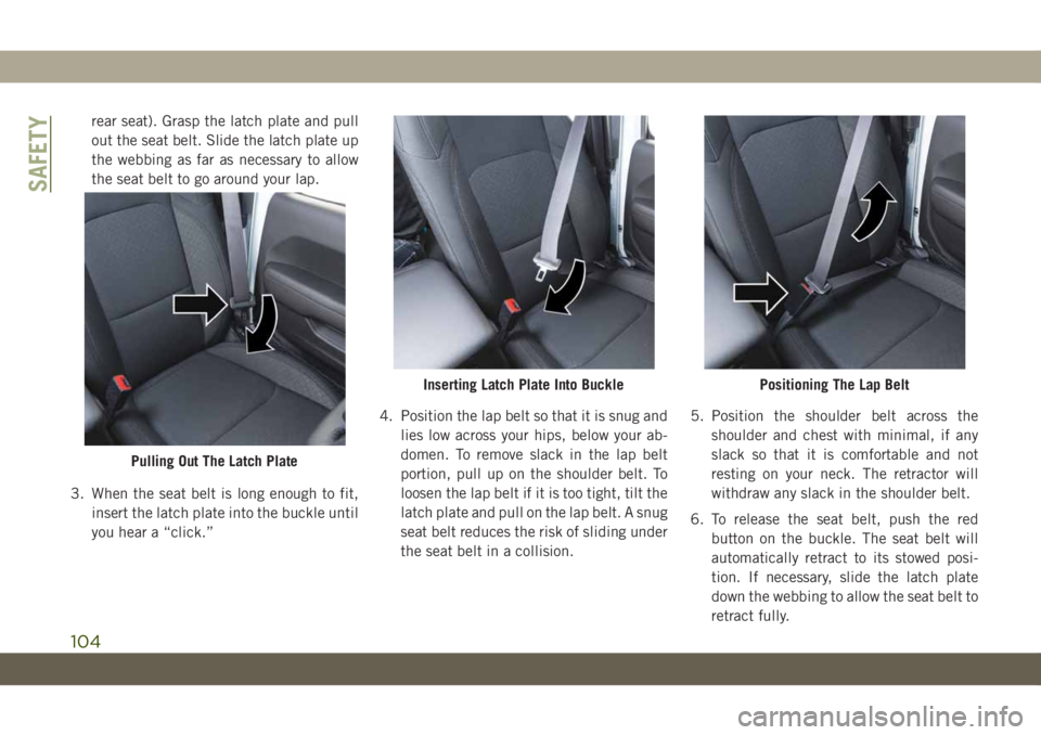
rear seat). Grasp the latch plate and pull
out the seat belt. Slide the latch plate up
the webbing as far as necessary to allow
the seat belt to go around your lap.
3. When the seat belt is long enough to fit,
insert the latch plate into the buckle until
you hear a “click.”4. Position the lap belt so that it is snug and
lies low across your hips, below your ab-
domen. To remove slack in the lap belt
portion, pull up on the shoulder belt. To
loosen the lap belt if it is too tight, tilt the
latch plate and pull on the lap belt. A snug
seat belt reduces the risk of sliding under
the seat belt in a collision.5. Position the shoulder belt across the
shoulder and chest with minimal, if any
slack so that it is comfortable and not
resting on your neck. The retractor will
withdraw any slack in the shoulder belt.
6. To release the seat belt, push the red
button on the buckle. The seat belt will
automatically retract to its stowed posi-
tion. If necessary, slide the latch plate
down the webbing to allow the seat belt to
retract fully.
Pulling Out The Latch Plate
Inserting Latch Plate Into BucklePositioning The Lap Belt
SAFETY
104
Page 134 of 348
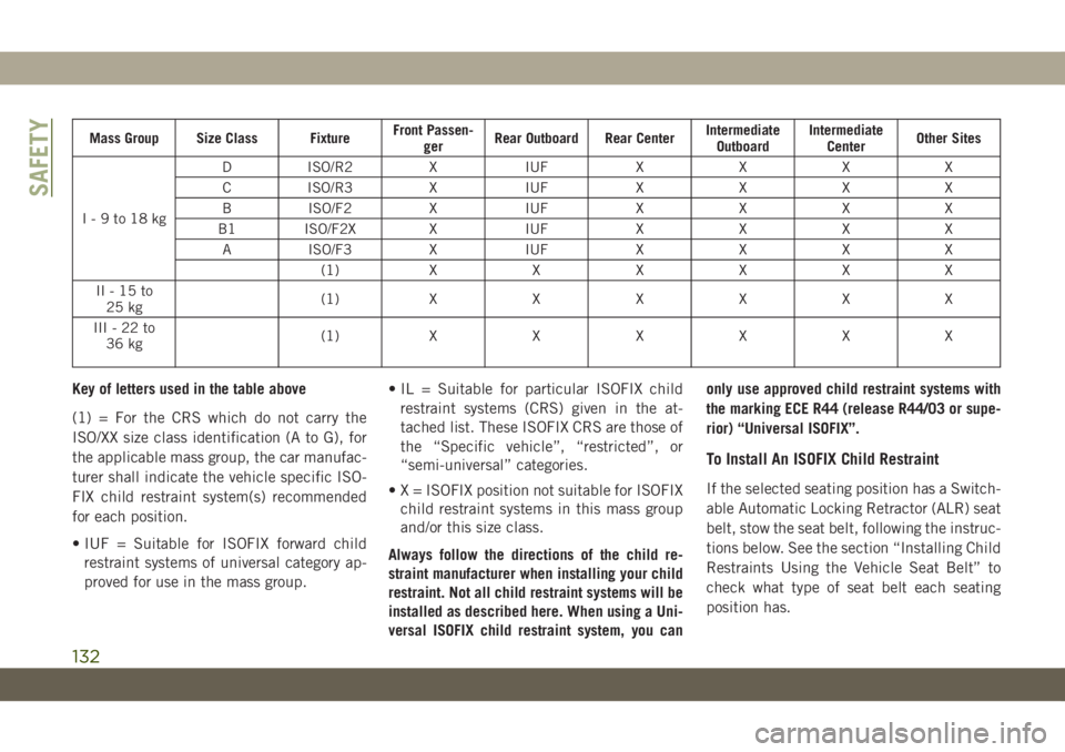
Mass Group Size Class FixtureFront Passen-
gerRear Outboard Rear CenterIntermediate
OutboardIntermediate
CenterOther Sites
I-9to18kgD ISO/R2 X IUF X X X X
C ISO/R3 X IUF X X X X
B ISO/F2 X IUF X X X X
B1 ISO/F2X X IUF X X X X
A ISO/F3 X IUF X X X X
(1)XXXXXX
II-15to
25 kg(1)XXXXXX
III-22to
36 kg(1)XXXXXX
Key of letters used in the table above
(1) = For the CRS which do not carry the
ISO/XX size class identification (A to G), for
the applicable mass group, the car manufac-
turer shall indicate the vehicle specific ISO-
FIX child restraint system(s) recommended
for each position.
• IUF = Suitable for ISOFIX forward child
restraint systems of universal category ap-
proved for use in the mass group.• IL = Suitable for particular ISOFIX child
restraint systems (CRS) given in the at-
tached list. These ISOFIX CRS are those of
the “Specific vehicle”, “restricted”, or
“semi-universal” categories.
• X = ISOFIX position not suitable for ISOFIX
child restraint systems in this mass group
and/or this size class.
Always follow the directions of the child re-
straint manufacturer when installing your child
restraint. Not all child restraint systems will be
installed as described here. When using a Uni-
versal ISOFIX child restraint system, you canonly use approved child restraint systems with
the marking ECE R44 (release R44/03 or supe-
rior) “Universal ISOFIX”.
To Install An ISOFIX Child Restraint
If the selected seating position has a Switch-
able Automatic Locking Retractor (ALR) seat
belt, stow the seat belt, following the instruc-
tions below. See the section “Installing Child
Restraints Using the Vehicle Seat Belt” to
check what type of seat belt each seating
position has.
SAFETY
132
Page 136 of 348
two posts. If not possible, lower the head
restraint and pass the tether strap around
the outboard side of the head restraint.
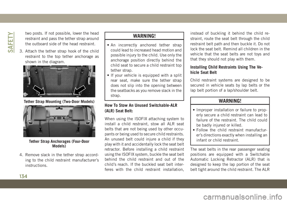
3. Attach the tether strap hook of the child
restraint to the top tether anchorage as
shown in the diagram.
4. Remove slack in the tether strap accord-
ing to the child restraint manufacturer’s
instructions.WARNING!
• An incorrectly anchored tether strap
could lead to increased head motion and
possible injury to the child. Use only the
anchorage position directly behind the
child seat to secure a child restraint top
tether strap.
• If your vehicle is equipped with a split
rear seat, make sure the tether strap
does not slip into the opening between
the seatbacks as you remove slack in the
strap.
How To Stow An Unused Switchable-ALR
(ALR) Seat Belt:
When using the ISOFIX attaching system to
install a child restraint, stow all ALR seat
belts that are not being used by other occu-
pants or being used to secure child restraints.
An unused belt could injure a child if they
play with it and accidentally lock the seat belt
retractor. Before installing a child restraint
using the ISOFIX system, buckle the seat belt
behind the child restraint and out of the
child’s reach. If the buckled seat belt inter-
feres with the child restraint installation,instead of buckling it behind the child re-
straint, route the seat belt through the child
restraint belt path and then buckle it. Do not
lock the seat belt. Remind all children in the
vehicle that the seat belts are not toys and
that they should not play with them.
Installing Child Restraints Using The Ve-
hicle Seat Belt
Child restraint systems are designed to be
secured in vehicle seats by lap belts or the
lap belt portion of a lap/shoulder belt.
WARNING!
• Improper installation or failure to prop-
erly secure a child restraint can lead to
failure of the restraint. The child could
be badly injured or killed.
• Follow the child restraint manufactur-
er’s directions exactly when installing an
infant or child restraint.
The seat belts in the rear passenger seating
positions are equipped with a Switchable
Automatic Locking Retractor (ALR) that is
designed to keep the lap portion of the seat
belt tight around the child restraint. The ALR
Tether Strap Mounting (Two-Door Models)
Tether Strap Anchorages (Four-Door
Models)
SAFETY
134
Page 141 of 348
WARNING!
• NEVER place any objects under the floor
mat (e.g., towels, keys, etc.). These ob-
jects could change the position of the
floor mat and may cause interference
with the accelerator, brake, or clutch
pedals.
• If the vehicle carpet has been removed
and re-installed, always properly attach
carpet to the floor and check the floor
mat fasteners are secure to the vehicle
carpet. Fully depress each pedal to
check for interference with the accelera-
tor, brake, or clutch pedals then re-
install the floor mats.
• It is recommended to only use mild soap
and water to clean your floor mats. After
cleaning, always check your floor mat
WARNING!
has been properly installed and is se-
cured to your vehicle using the floor mat
fasteners by lightly pulling mat.
Periodic Safety Checks You Should Make
Outside The Vehicle
Tires
Examine tires for excessive tread wear and
uneven wear patterns. Check for stones,
nails, glass, or other objects lodged in the
tread or sidewall. Inspect the tread for cuts
and cracks. Inspect sidewalls for cuts,
cracks, and bulges. Check the wheel nuts for
tightness. Check the tires (including spare)
for proper cold inflation pressure.
Lights
Have someone observe the operation of brake
lights and exterior lights while you work the
controls. Check turn signal and high beam
indicator lights on the instrument panel.
Door Latches
Check for proper closing, latching, and lock-
ing.
Fluid Leaks
Check area under the vehicle after overnight
parking for fuel, coolant, oil, or other fluid
leaks. Also, if gasoline fumes are detected or
if fuel, or brake fluid leaks are suspected. The
cause should be located and corrected imme-
diately.
139
Page 143 of 348
STARTING AND OPERATING
STARTING THE ENGINE.......142
Normal Starting — Gasoline Engine . . .142
Normal Starting — Diesel Engine. . . .145
ENGINE BREAK-IN RECOMMENDA-
TIONS....................146
AUTOMATIC TRANSMISSION . . .147
Ignition Park Interlock...........148
Brake/Transmission Shift Interlock
System....................148
Eight–Speed Automatic Transmission . .148
FOUR–WHEEL DRIVE OPERA-
TION.....................150
Four-Position Transfer Case........150
Five-Position Transfer Case........153
Trac-Lok Rear Axle — If Equipped . . .155
Axle Lock (Tru-Lok) — Rubicon Models
.........................156
Electronic Sway Bar Disconnect — If
Equipped...................156
STOP/START SYSTEM — AUTOMATIC
TRANSMISSION (IF EQUIPPED)
. .157
Automatic Mode...............158
Possible Reasons The Engine Does Not
Autostop...................158
To Start The Engine While In Autostop
Mode.....................159
To Manually Turn Off The Stop/Start
System....................159
To Manually Turn On The Stop/Start
System....................160
System Malfunction............160
SPEED CONTROL...........160
To Activate..................161
To Set A Desired Speed..........161
To Vary The Speed Setting.........161
To Accelerate For Passing.........162
To Resume Speed.............162
To Deactivate................162
PARKSENSE REAR PARK ASSIST —
IF EQUIPPED...............163
ParkSense Sensors.............163
Enabling And Disabling ParkSense . . .163
ParkSense System Usage Precautions . .163
PARKVIEW REAR BACK UP CAM-
ERA — IF EQUIPPED..........165
REFUELING THE VEHICLE.....166
Fuel Filler Cap...............166
Loose Fuel Filler Cap Message......167
REFUELING THE VEHICLE — DIE-
SEL......................167
Adblue (UREA) — If Equipped......168
TRAILER TOWING...........171
Trailer Towing Weights (Maximum Trailer
Weight Ratings)...............171
RECREATIONAL TOWING (BEHIND
MOTORHOME, ETC.).........171
Towing This Vehicle Behind Another
Vehicle....................171
Recreational Towing — Four-Wheel Drive
Models....................172
STARTING AND OPERATING
141
Page 151 of 348
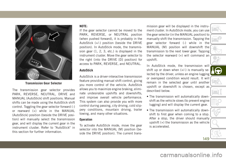
The transmission gear selector provides
PARK, REVERSE, NEUTRAL, DRIVE and
MANUAL (AutoStick) shift positions. Manual
shifts can be made using the AutoStick shift
control. Toggling the gear selector forward (-)
or rearward (+) while in the MANUAL
(AutoStick) position (beside the DRIVE posi-
tion) will manually select the transmission
gear, and will display the current gear in the
instrument cluster. Refer to "AutoStick" in
this section for further information.NOTE:
If the gear selector cannot be moved to the
PARK, REVERSE, or NEUTRAL position
(when pushed forward), it is probably in the
AutoStick (+/-) position (beside the DRIVE
position). In AutoStick mode, the transmis-
sion gear (1, 2, 3, etc.) is displayed in the
instrument cluster. Move the gear selector to
the right (into the DRIVE [D] position) for
access to PARK, REVERSE, and NEUTRAL.
AutoStick
AutoStick is a driver-interactive transmission
feature providing manual shift control, giving
you more control of the vehicle. AutoStick
allows you to maximize engine braking, elimi-
nate undesirable upshifts and downshifts,
and improve overall vehicle performance.
This system can also provide you with more
control during passing, city driving, cold slip-
pery conditions, mountain driving, trailer
towing, and many other situations.
Operation
To activate AutoStick mode, move the gear
selector into the MANUAL (M) position (be-
side the DRIVE position). The current trans-mission gear will be displayed in the instru-
ment cluster. In AutoStick mode, you can use
the gear selector (in the MANUAL position) to
manually shift the transmission. Tapping the
gear selector forward (-) while in the
MANUAL (M) position will downshift the
transmission to the next lower gear. Tapping
the selector rearward (+) will command an
upshift.
In AutoStick mode, the transmission will
shift up or down when (+/-) is manually se-
lected by the driver, unless an engine lugging
or overspeed condition would result. It will
remain in the selected gear until another
upshift or downshift is chosen, except as
described below.
• The transmission will automatically down-
shift as the vehicle slows (to prevent engine
lugging) and will display the current gear.
• The transmission will automatically down-
shift to first gear when coming to a stop.
After a stop, the driver should manually
upshift (+) the transmission as the vehicle
is accelerated.
Transmission Gear Selector
149
Page 153 of 348
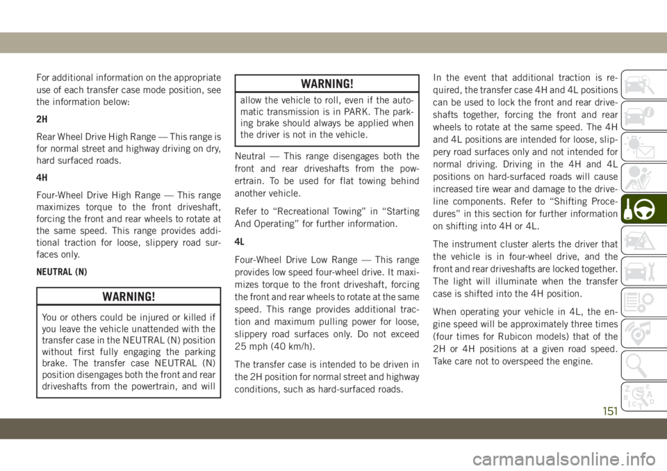
For additional information on the appropriate
use of each transfer case mode position, see
the information below:
2H
Rear Wheel Drive High Range — This range is
for normal street and highway driving on dry,
hard surfaced roads.
4H
Four-Wheel Drive High Range — This range
maximizes torque to the front driveshaft,
forcing the front and rear wheels to rotate at
the same speed. This range provides addi-
tional traction for loose, slippery road sur-
faces only.
NEUTRAL (N)
WARNING!
You or others could be injured or killed if
you leave the vehicle unattended with the
transfer case in the NEUTRAL (N) position
without first fully engaging the parking
brake. The transfer case NEUTRAL (N)
position disengages both the front and rear
driveshafts from the powertrain, and will
WARNING!
allow the vehicle to roll, even if the auto-
matic transmission is in PARK. The park-
ing brake should always be applied when
the driver is not in the vehicle.
Neutral — This range disengages both the
front and rear driveshafts from the pow-
ertrain. To be used for flat towing behind
another vehicle.
Refer to “Recreational Towing” in “Starting
And Operating” for further information.
4L
Four-Wheel Drive Low Range — This range
provides low speed four-wheel drive. It maxi-
mizes torque to the front driveshaft, forcing
the front and rear wheels to rotate at the same
speed. This range provides additional trac-
tion and maximum pulling power for loose,
slippery road surfaces only. Do not exceed
25 mph (40 km/h).
The transfer case is intended to be driven in
the 2H position for normal street and highway
conditions, such as hard-surfaced roads.In the event that additional traction is re-
quired, the transfer case 4H and 4L positions
can be used to lock the front and rear drive-
shafts together, forcing the front and rear
wheels to rotate at the same speed. The 4H
and 4L positions are intended for loose, slip-
pery road surfaces only and not intended for
normal driving. Driving in the 4H and 4L
positions on hard-surfaced roads will cause
increased tire wear and damage to the drive-
line components. Refer to “Shifting Proce-
dures” in this section for further information
on shifting into 4H or 4L.
The instrument cluster alerts the driver that
the vehicle is in four-wheel drive, and the
front and rear driveshafts are locked together.
The light will illuminate when the transfer
case is shifted into the 4H position.
When operating your vehicle in 4L, the en-
gine speed will be approximately three times
(four times for Rubicon models) that of the
2H or 4H positions at a given road speed.
Take care not to overspeed the engine.
151
Page 155 of 348
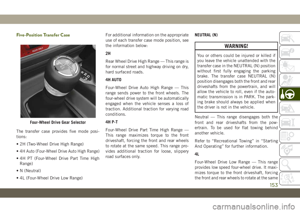
Five-Position Transfer Case
The transfer case provides five mode posi-
tions:
• 2H (Two-Wheel Drive High Range)
•
4H Auto (Four-Wheel Drive Auto High Range)
• 4H PT (Four-Wheel Drive Part Time High
Range)
• N (Neutral)
• 4L (Four-Wheel Drive Low Range)For additional information on the appropriate
use of each transfer case mode position, see
the information below:
2H
Rear Wheel Drive High Range — This range is
for normal street and highway driving on dry,
hard surfaced roads.
4H AUTO
Four-Wheel Drive Auto High Range — This
range sends power to the front wheels. The
four-wheel drive system will be automatically
engaged when the vehicle senses a loss of
traction. Additional traction for varying road
conditions.
4H P-T
Four-Wheel Drive Part Time High Range —
This range maximizes torque to the front
driveshaft, forcing the front and rear wheels
to rotate at the same speed. This range pro-
vides additional traction for loose, slippery
road surfaces only.NEUTRAL (N)
WARNING!
You or others could be injured or killed if
you leave the vehicle unattended with the
transfer case in the NEUTRAL (N) position
without first fully engaging the parking
brake. The transfer case NEUTRAL (N)
position disengages both the front and rear
driveshafts from the powertrain, and will
allow the vehicle to roll, even if the auto-
matic transmission is in PARK. The park-
ing brake should always be applied when
the driver is not in the vehicle.
Neutral — This range disengages both the
front and rear driveshafts from the pow-
ertrain. To be used for flat towing behind
another vehicle.
Refer to “Recreational Towing” in “Starting
And Operating” for further information.
4L
Four-Wheel Drive Low Range — This range
provides low speed four-wheel drive. It maxi-
mizes torque to the front driveshaft, forcing
the front and rear wheels to rotate at the same
Four-Wheel Drive Gear Selector
153