reset JEEP WRANGLER UNLIMITED 2018 Owner handbook (in English)
[x] Cancel search | Manufacturer: JEEP, Model Year: 2018, Model line: WRANGLER UNLIMITED, Model: JEEP WRANGLER UNLIMITED 2018Pages: 348, PDF Size: 6.5 MB
Page 61 of 348
CAUTION!
life and/or prevent the engine from start-
ing.
• Accessories that draw higher power (i.e.,
coolers, vacuum cleaners, lights, etc.),
will degrade the battery even more
quickly. Only use these intermittently
and with greater caution.
• After the use of high power draw acces-
sories, or long periods of the vehicle not
being started (with accessories still
plugged in), the vehicle must be driven a
sufficient length of time to allow the
alternator to recharge the vehicle's bat-
tery.
• Power outlets are designed for accessory
plugs only. Do not hang any type of
accessory or accessory bracket from the
plug. Improper use of the power outlet
can cause damage.
Power Inverter — If Equipped
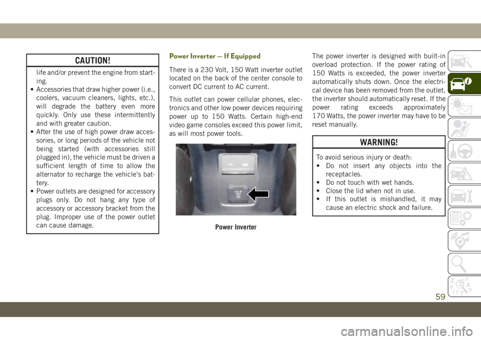
There is a 230 Volt, 150 Watt inverter outlet
located on the back of the center console to
convert DC current to AC current.
This outlet can power cellular phones, elec-
tronics and other low power devices requiring
power up to 150 Watts. Certain high-end
video game consoles exceed this power limit,
as will most power tools.The power inverter is designed with built-in
overload protection. If the power rating of
150 Watts is exceeded, the power inverter
automatically shuts down. Once the electri-
cal device has been removed from the outlet,
the inverter should automatically reset. If the
power rating exceeds approximately
170 Watts, the power inverter may have to be
reset manually.
WARNING!
To avoid serious injury or death:
• Do not insert any objects into the
receptacles.
• Do not touch with wet hands.
• Close the lid when not in use.
• If this outlet is mishandled, it may
cause an electric shock and failure.
Power Inverter
59
Page 65 of 348
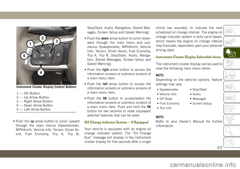
• Push theuparrow button to scroll upward
through the main menus (Speedometer,
MPH/km/h, Vehicle Info, Terrain, Driver As-
sist, Fuel Economy, Trip A, Trip B,Stop/Start, Audio, Navigation, Stored Mes-
sages, Screen Setup and Speed Warning).
• Push thedownarrow button to scroll down-
ward through the main menu and sub-
menus (Speedometer, MPH/km/h, Vehicle
Info, Terrain, Driver Assist, Fuel Economy,
Trip A, Trip B, Stop/Start, Audio, Naviga-
tion, Stored Messages, Screen Setup and
Speed Warning).
• Push therightarrow button to access the
information screens or submenu screens of
a main menu item.
• Push theleftarrow button to access the
information screens or submenu screens of
a main menu item.
• Push theOKbutton to access/select the
information screens or submenu screens of
a main menu item. Push and hold theOK
button for two seconds to reset displayed/
selected features that can be reset.Oil Change Indicator System — If Equipped
Your vehicle is equipped with an engine oil
change indicator system. The “Oil Change
Due” message will display in the instrument
cluster display for five seconds after a singlechime has sounded, to indicate the next
scheduled oil change interval. The engine oil
change indicator system is duty cycle based,
which means the engine oil change interval
may fluctuate, dependent upon your personal
driving style.
Instrument Cluster Display Selectable Items
The instrument cluster display can be used to
view the following main menu items:
NOTE:
Depending on the vehicles options, feature
settings may vary.
• Speedometer • Stop/Start
• Vehicle Info • Audio
• Off Road • Messages
• Fuel Economy • Screen Setup
• Trip Info
NOTE:
Refer to your Owner’s Manual for further
information.
Instrument Cluster Display Control Buttons
1 — OK Button
2 — Up Arrow Button
3 — Right Arrow Button
4 — Down Arrow Button
5 — Left Arrow Button
63
Page 121 of 348
• As the air bags deflate, you may see some
smoke-like particles. The particles are a
normal by-product of the process that gen-
erates the non-toxic gas used for air bag
inflation. These airborne particles may irri-
tate the skin, eyes, nose, or throat. If you
have skin or eye irritation, rinse the area
with cool water. For nose or throat irritation,
move to fresh air. If the irritation continues,
see your doctor. If these particles settle on
your clothing, follow the garment manufac-
turer’s instructions for cleaning.
Do not drive your vehicle after the air bags
have deployed. If you are involved in another
collision, the air bags will not be in place to
protect you.
WARNING!
Deployed air bags and seat belt preten-
sioners cannot protect you in another col-
lision. Have the air bags, seat belt preten-
sioners, and the seat belt retractor
assemblies replaced by an authorized
dealer immediately. Also, have the Occu-
pant Restraint Controller System serviced
as well.NOTE:
• Air bag covers may not be obvious in the
interior trim, but they will open during air
bag deployment.
• After any collision, the vehicle should be
taken to an authorized dealer immediately.
Enhanced Accident Response System
In the event of an impact, if the communica-
tion network remains intact, and the power
remains intact, depending on the nature of
the event, the ORC will determine whether to
have the Enhanced Accident Response Sys-
tem perform the following functions:
• Cut off fuel to the engine (If Equipped)
• Cut off battery power to the electric motor
(If Equipped)
• Flash hazard lights as long as the battery
has power
• Turn on the interior lights, which remain on
as long as the battery has power or for 15
minutes from the intervention of the En-
hanced Accident Response System.
• Unlock the power door locks.Your vehicle may also be designed to perform
any of these other functions in response to
the Enhanced Accident Response System:
• Turn off the Fuel Filter Heater, Turn off the
HVAC Blower Motor, Close the HVAC Circu-
lation Door
• Cut off battery power to the:
– Engine
– Electric Motor (if equipped)
– Electric power steering
– Brake booster
– Electric park brake
– Automatic transmission gear selector
– Horn
– Front wiper
– Headlamp washer pump
NOTE:
After an accident, remember to cycle the
ignition to the STOP (OFF/LOCK) position
and remove the key from the ignition switch
to avoid draining the battery. Carefully check
the vehicle for fuel leaks in the engine com-
partment and on the ground near the engine
compartment and fuel tank before resetting
the system and starting the engine. If there
are no fuel leaks or damage to the vehicle
119
Page 122 of 348

electrical devices (e.g. headlights) after an
accident, reset the system by following the
procedure described below. If you have any
doubt, contact an authorized dealer.
Enhanced Accident Response System Reset
Procedure
In order to reset the Enhanced Accident Re-
sponse System functions after an event, the
ignition switch must be changed from igni-
tion START or ON/RUN to ignition OFF. Care-
fully check the vehicle for fuel leaks in the
engine compartment and on the ground near
the engine compartment and fuel tank before
resetting the system and starting the engine.
Maintaining Your Air Bag System
WARNING!
• Modifications to any part of the air bag
system could cause it to fail when you
need it. You could be injured if the air
bag system is not there to protect you.
Do not modify the components or wiring,
including adding any kind of badges or
stickers to the steering wheel hub trim
WARNING!
cover or the upper passenger side of the
instrument panel. Do not modify the
front bumper, vehicle body structure, or
add aftermarket side steps or running
boards.
• It is dangerous to try to repair any part of
the air bag system yourself. Be sure to
tell anyone who works on your vehicle
that it has an air bag system.
• Do not attempt to modify any part of your
air bag system. The air bag may inflate
accidentally or may not function prop-
erly if modifications are made. Take your
vehicle to an authorized dealer for any
air bag system service. If your seat, in-
cluding your trim cover and cushion,
needs to be serviced in any way (includ-
ing removal or loosening/tightening of
seat attachment bolts), take the vehicle
to an authorized dealer. Only manufac-
turer approved seat accessories may be
used. If it is necessary to modify the air
bag system for persons with disabilities,
contact an authorized dealer.
Event Data Recorder (EDR)
This vehicle is equipped with an event data
recorder (EDR). The main purpose of an EDR
is to record, in certain crash or near crash-
like situations, such as an air bag deployment
or hitting a road obstacle, data that will assist
in understanding how a vehicle’s systems
performed. The EDR is designed to record
data related to vehicle dynamics and safety
systems for a short period of time, typically
30 seconds or less. The EDR in this vehicle is
designed to record such data as:
• How various systems in your vehicle were
operating;
• Whether or not the driver and passenger
safety belts were buckled/fastened;
• How far (if at all) the driver was depressing
the accelerator and/or brake pedal; and,
• How fast the vehicle was traveling.
These data can help provide a better under-
standing of the circumstances in which
crashes and injuries occur.
SAFETY
120
Page 162 of 348
3. At the next vehicle stop (after turning off
the STOP/START system), the engine will
not be stopped.
4. The STOP/START system will reset itself
back to an ON condition every time the
ignition is turned off and back on.
To Manually Turn On The Stop/Start
System
Push the STOP/START OFF switch (located
on the switch bank). The light on the switch
will turn off.
For complete details on the Stop/Start Sys-
tem refer to the “Stop/Start System” in the
“Starting And Operating” section located in
your Owner’s Manual for further information.
System Malfunction
If there is a malfunction in the STOP/START
system, the system will not shut down the
engine. A “SERVICE STOP/START SYSTEM”
message will appear in the instrument cluster
display. Refer to “Instrument Cluster Dis-
play“ in “Getting to Know Your Instrument
Panel” for further information.
If the “SERVICE STOP/START SYSTEM”
message appears in the instrument cluster
display, have the system checked by an au-
thorized dealer.
SPEED CONTROL
When engaged, the Speed Control takes over
accelerator operations at speeds greater than
20 mph (32 km/h).
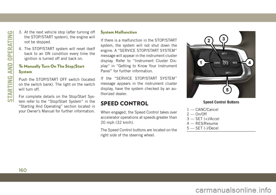
The Speed Control buttons are located on the
right side of the steering wheel.
Speed Control Buttons
1 — CANC/Cancel
2 — On/Off
3 — SET (+)/Accel
4 — RES/Resume
5 — SET (-)/Decel
STARTING AND OPERATING
160
Page 163 of 348
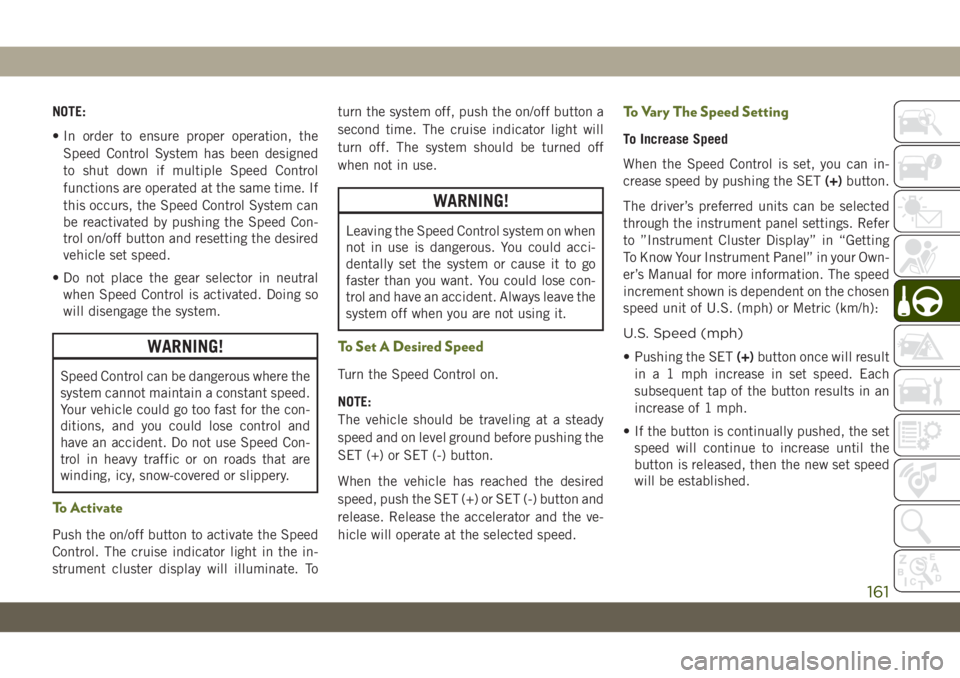
NOTE:
• In order to ensure proper operation, the
Speed Control System has been designed
to shut down if multiple Speed Control
functions are operated at the same time. If
this occurs, the Speed Control System can
be reactivated by pushing the Speed Con-
trol on/off button and resetting the desired
vehicle set speed.
• Do not place the gear selector in neutral
when Speed Control is activated. Doing so
will disengage the system.
WARNING!
Speed Control can be dangerous where the
system cannot maintain a constant speed.
Your vehicle could go too fast for the con-
ditions, and you could lose control and
have an accident. Do not use Speed Con-
trol in heavy traffic or on roads that are
winding, icy, snow-covered or slippery.
To Activate
Push the on/off button to activate the Speed
Control. The cruise indicator light in the in-
strument cluster display will illuminate. Toturn the system off, push the on/off button a
second time. The cruise indicator light will
turn off. The system should be turned off
when not in use.
WARNING!
Leaving the Speed Control system on when
not in use is dangerous. You could acci-
dentally set the system or cause it to go
faster than you want. You could lose con-
trol and have an accident. Always leave the
system off when you are not using it.
To Set A Desired Speed
Turn the Speed Control on.
NOTE:
The vehicle should be traveling at a steady
speed and on level ground before pushing the
SET (+) or SET (-) button.
When the vehicle has reached the desired
speed, push the SET (+) or SET (-) button and
release. Release the accelerator and the ve-
hicle will operate at the selected speed.
To Vary The Speed Setting
To Increase Speed
When the Speed Control is set, you can in-
crease speed by pushing the SET(+)button.
The driver’s preferred units can be selected
through the instrument panel settings. Refer
to ”Instrument Cluster Display” in “Getting
To Know Your Instrument Panel” in your Own-
er’s Manual for more information. The speed
increment shown is dependent on the chosen
speed unit of U.S. (mph) or Metric (km/h):
U.S. Speed (mph)
• Pushing the SET(+)button once will result
in a 1 mph increase in set speed. Each
subsequent tap of the button results in an
increase of 1 mph.
• If the button is continually pushed, the set
speed will continue to increase until the
button is released, then the new set speed
will be established.
161
Page 169 of 348
WARNING!
• Do not apply any object/cap to the end of
the filler which is not provided for the
car. The use of non-compliant objects/
plugs could cause a pressure increase
inside the tank, resulting in dangerous
situations.
• A fire may result if fuel is pumped into a
portable container that is inside of a
vehicle. You could be burned. Always
place fuel containers on the ground
while filling.
CAUTION!
• Damage to the fuel system or emission
control system could result from using
an improper fuel filler cap. A poorly
fitting cap could let impurities into the
fuel system. Also, a poorly fitting after-
market cap can cause the “Malfunction
Indicator Light (MIL)” to illuminate, due
to fuel vapors escaping from the system.
• To avoid fuel spillage and overfilling, do
not “top off” the fuel tank after filling.NOTE:
• When the fuel nozzle “clicks” or shuts off,
the fuel tank is full.
• Tighten the fuel filler cap about 1/4 turn
until you hear one click. This is an indica-
tion that the cap is properly tightened.
• If the fuel filler cap is not tightened prop-
erly, the MIL will come on. Be sure the cap
is tightened every time the vehicle is
refueled.
Loose Fuel Filler Cap Message
After fuel has been added, the vehicle diag-
nostic system can determine if the fuel filler
cap is possibly loose, improperly installed, or
damaged. If the system detects a malfunc-
tion, the “gASCAP” message will display in
the odometer display. Tighten the gas cap
until a "clicking" sound is heard. This is an
indication that the gas cap is properly tight-
ened. Push the odometer reset button to turn
the message off. If the problem persists, the
message will appear the next time the vehicle
is started. This might indicate a damagedcap. If the problem is detected twice in a row,
the system will turn on the MIL. Resolving the
problem will turn the MIL off.
REFUELING THE VEHICLE —
DIESEL
The fuel filler cap is located on the driver's
side of the vehicle. If the fuel filler cap is lost
or damaged, be sure the replacement cap is
the correct one for this vehicle.
Fuel Filler Door
167
Page 203 of 348
To Reset The Manual Park Release:
1. Pull upward on the tether strap, releasing
it from the “locked” position.
2. Lower the Manual Park Release lever
downward and to the right, into its original
position.
3. Tuck the tether strap into the base of the
console, and reinstall the cover.
FREEING A STUCK VEHICLE
If your vehicle becomes stuck in mud, sand or
snow, it can often be moved using a rocking
motion. Turn the steering wheel right and left
to clear the area around the front wheels. For
vehicles with automatic transmission, push
and hold the lock button on the gear selector.
Then, shift back and forth between DRIVE
and REVERSE, while gently pressing the ac-
celerator. Use the least amount of accelerator
pedal pressure that will maintain the rocking
motion, without spinning the wheels or racing
the engine.NOTE:
• For vehicles with automatic transmission:
Shifts between DRIVE and REVERSE can
only be achieved at wheel speeds of 5 mph
(8 km/h) or less. Whenever the transmis-
sion remains in NEUTRAL for more than
2 seconds, you must press the brake pedal
to engage DRIVE or REVERSE.
• Push the "ESC Off" switch, to place the
Electronic Stability Control (ESC) system in
"Partial Off" mode, before rocking the ve-
hicle. Refer to “Electronic Brake Control
System” in “Safety” in your Owner’s
Manual for further details. Once the vehicle
has been freed, push the "ESC Off" switch
again to restore "ESC On" mode.
WARNING!
Fast spinning tires can be dangerous.
Forces generated by excessive wheel
speeds may cause damage, or even failure,
of the axle and tires. A tire could explode
and injure someone. Do not spin your ve-
hicle's wheels faster than 30 mph
(48 km/h) or for longer than 30 seconds
continuously without stopping when you
WARNING!
are stuck and do not let anyone near a
spinning wheel, no matter what the speed.
CAUTION!
• Racing the engine or spinning the
wheels may lead to transmission over-
heating and failure. Allow the engine to
idle with the transmission in NEUTRAL
for at least one minute after every five
rocking-motion cycles. This will mini-
mize overheating and reduce the risk of
clutch or transmission failure during
prolonged efforts to free a stuck vehicle.
• When “rocking” a stuck vehicle by shift-
ing between DRIVE/SECOND GEAR and
REVERSE, do not spin the wheels faster
than 15 mph (24 km/h), or drivetrain
damage may result.
• Revving the engine or spinning the
wheels too fast may lead to transmission
overheating and failure. It can also dam-
age the tires. Do not spin the wheels
above 30 mph (48 km/h) while in gear
(no transmission shifting occurring).
201
Page 211 of 348
Your authorized dealer will reset the oil
change indicator message after completing
the scheduled oil change.
Once A Month Or Before A Long Trip
• Check the engine oil level about five min-
utes after a fully warmed engine is shut off.
Checking the oil level while the vehicle is
on level ground will improve the accuracy of
the oil level reading. Add oil only when the
level is at or below the ADD or MIN mark.
• Check the windshield washer solvent and
add if required.
• Check tire pressure and look for unusual
wear or damage. Rotate tires at the first
sign of irregular wear, even if it occurs
before the oil indicator system turns on.• Inspect the battery and clean and tighten
the terminals as required.
• Check the fluid levels of coolant reservoir,
brake master cylinder and power steering
and fill as needed.
• Check all lights and other electrical items
for correct operation.
At Each Oil Change
• Change the engine oil filter.
• Inspect the brake hoses and lines.
CAUTION!
Failure to perform the required mainte-
nance items may result in damage to the
vehicle.Required Maintenance Intervals
Refer to the Maintenance Plan on the follow-
ing pages for the required maintenance inter-
vals.
Maintenance Plan
NOTE:
Once you have carried out the last interven-
tion in the table, continue with the scheduled
servicing, maintaining the frequency indi-
cated in the plan by marking each operation
with a dot or dedicated note. Simply restart-
ing the maintenance from the start of the
plan may cause the allowed interval to be
exceeded for some operations.
209
Page 227 of 348
light is on. If necessary, add fluid to bring
level within the designated marks on the side
of the reservoir of the brake master cylinder.
Be sure to clean the top of the master cylin-
der area before removing cap. With disc
brakes, fluid level can be expected to fall as
the brake pads wear. Brake fluid level should
be checked when pads are replaced. If the
brake fluid is abnormally low, check the sys-
tem for leaks.
Refer to “Fluids And Lubricants” in “Techni-
cal Specifications” for further information.
WARNING!
• Brake fluid is poisonous and highly cor-
rosive. In the event of accidental con-
tact, immediately wash the affected
parts with water and neutral soap. Then
rinse thoroughly. Call a doctor immedi-
ately if swallowed.
• Use only manufacturer's recommended
brake fluid. Refer to “Fluids And Lubri-
cants” in “Technical Specifications” for
further information. Using the wrong
type of brake fluid can severely damage
WARNING!
your brake system and/or impair its per-
formance. The proper type of brake fluid
for your vehicle is also identified on the
original factory installed hydraulic mas-
ter cylinder reservoir.
• To avoid contamination from foreign
matter or moisture, use only new brake
fluid or fluid that has been in a tightly
closed container. Keep the master cylin-
der reservoir cap secured at all times.
Brake fluid in a open container absorbs
moisture from the air resulting in a lower
boiling point. This may cause it to boil
unexpectedly during hard or prolonged
braking, resulting in sudden brake fail-
ure. This could result in a collision.
• Overfilling the brake fluid reservoir can
result in spilling brake fluid on hot en-
gine parts, causing the brake fluid to
catch fire. Brake fluid can also damage
painted and vinyl surfaces, care should
be taken to avoid its contact with these
surfaces.
• Do not allow petroleum based fluid to
contaminate the brake fluid. Brake seal
WARNING!
components could be damaged, causing
partial or complete brake failure. This
could result in a collision.
Automatic Transmission
Fluid Level Check
The fluid level is preset at the factory and
does not require adjustment under normal
operating conditions. Routine fluid level
checks are not required; therefore the trans-
mission has no dipstick. An authorized dealer
can check your transmission fluid level using
special service tools. If you notice fluid leak-
age or transmission malfunction, visit an au-
thorized dealer immediately to have the
transmission fluid level checked. Operating
the vehicle with an improper fluid level can
cause severe transmission damage.
CAUTION!
If a transmission fluid leak occurs, visit an
authorized dealer immediately. Severe
transmission damage may occur. An au-
225