steering JEEP WRANGLER UNLIMITED 2018 Owner handbook (in English)
[x] Cancel search | Manufacturer: JEEP, Model Year: 2018, Model line: WRANGLER UNLIMITED, Model: JEEP WRANGLER UNLIMITED 2018Pages: 348, PDF Size: 6.5 MB
Page 3 of 348
Congratulations on selecting your new FCA
vehicle. Be assured that it represents preci-
sion workmanship, distinctive styling, and
high quality.
ALWAYS drive safely and pay attention to the
road. ALWAYS drive safely with your hands on
the steering wheel. You have full responsibil-
ity and assume all risks related to the use of
the features and applications in this vehicle.
Only use the features and applications when
it is safe to do so. Failure to do so may result
in an accident involving serious injury or
death.
This guide illustrates and describes the op-
eration of features and equipment that are
either standard or optional on this vehicle.
This guide may also include a description of
features and equipment that are no longer
available or were not ordered on this vehicle.
Please disregard any features and equipment
described in this guide that are not available
on this vehicle. FCA reserves the right to
make changes in design and specificationsand/or make additions to or improvements to
its products without imposing any obligation
upon itself to install them on products previ-
ously manufactured.
This User Guide has been prepared to help
you quickly become acquainted with the im-
portant features of your vehicle. It contains
most things you will need to operate and
maintain the vehicle, including emergency
information.
When it comes to service, remember that your
authorized dealer knows your Jeep
®vehicle
best, has factory-trained technicians and
genuine MOPAR
®parts, and cares about your
satisfaction.
HOW TO FIND YOUR
OWNER’S MANUAL ONLINE
This publication has been prepared as a ref-
erence item to help you quickly become ac-
quainted with the most important features
and processes of your vehicle. It contains
most things you will need to operate and
maintain the vehicle, including emergency
information and procedures.This User Guide is not a replacement for the full
Owner’s Manual, and does not fully cover every
operation and procedure possible with your ve-
hicle.
For more detailed descriptions of the topics
discussed in this User Guide, as well as
information covering features and processes
not covered in this User Guide, the full ve-
hicle Owner’s Manual can be accessed for
free online in a printer-friendly PDF format.
To get the full Owner’s Manual or applicable
supplement for your vehicle, follow the appro-
priate web address below:
www.mopar.eu/owneror alternatively, to ac-
cess this information, go to the Internet web-
site athttp://aftersales.fiat.com/elum/.
FCA is committed to protecting our environ-
ment and natural resources. By converting
from paper to electronic delivery for the ma-
jority of the user information for your vehicle,
together we greatly reduce the demand for
tree-based products and lessen the stress on
our environment.
1
Page 11 of 348
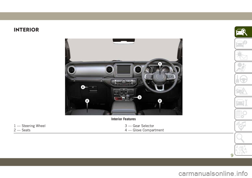
INTERIOR
Interior Features
1 — Steering Wheel 3 — Gear Selector
2 — Seats 4 — Glove Compartment
9
Page 13 of 348
GETTING TO KNOW YOUR VEHICLE
KEYS .....................13
KeyFob.....................13
IGNITION SWITCH............15
Keyless Enter-N-Go — Ignition.......15
REMOTE STARTING SYSTEM — IF
EQUIPPED.................16
How To Use Remote Start..........16
To Enter Remote Start Mode........17
VEHICLE SECURITY ALARM — IF
EQUIPPED..................17
To Arm The System.............17
To Disarm The System............18
DOORS....................18
Keyless Enter-N-Go — Passive Entry (If
Equipped)...................18
Child-Protection Door Lock System — Rear
Doors......................21
Front Door Removal.............22
Rear Door Removal (Four-Door Models) . .24
SEATS ....................26
Heated Seats — If Equipped........26Front Passenger Easy Entry Seat — Two
Door Models..................27
60/40 Split Folding Rear Seat — Four Door
Models.....................28
Fold And Tumble Rear Seat — Two Door
Models.....................29
HEAD RESTRAINTS...........30
Front Head Restraints............30
Rear Head Restraints — Two Door
Models.....................31
Rear Head Restraints — Four Door
Models.....................32
STEERING WHEEL............33
Tilt/Telescoping Steering Column......33
Heated Steering Wheel — If Equipped . .34
MIRRORS..................35
Heated Mirrors — If Equipped.......35
EXTERIOR LIGHTS...........35
Headlight Switch...............35
Daytime Running Lights — If Equipped .35
High/Low Beam Switch...........35
Flash-To-Pass.................36Automatic Headlights — If Equipped . . .36
Front And Rear Fog Lights — If
Equipped...................36
Turn Signals..................36
Lane Change Assist — If Equipped....37
Lights-On Reminder.............37
Headlight Leveling System — If
Equipped...................37
WINDSHIELD WIPERS AND WASH-
ERS ......................37
Windshield Wiper Operation.........38
CLIMATE CONTROLS..........39
Automatic Climate Controls Overview . . .39
Climate Control Functions..........44
Automatic Temperature Control (ATC) — If
Equipped....................44
Operating Tips................45
POWER WINDOWS — IF
EQUIPPED.................46
Auto-Down Feature..............46
Wind Buffeting................47
GETTING TO KNOW YOUR VEHICLE
11
Page 18 of 348
WARNING!
could operate power windows, other con-
trols, or move the vehicle.
• Do not leave children or animals inside
parked vehicles in hot weather. Interior
heat build-up may cause serious injury
or death.
CAUTION!
An unlocked vehicle is an invitation for
thieves. Always remove key fob from the
vehicle and lock all doors when leaving the
vehicle unattended.
NOTE:
Refer to "Starting The Engine," in "Starting
And Operating" in the Owner’s Manual for
further information.
REMOTE STARTING
SYSTEM — IF EQUIPPED
This system uses the key fob to
start the engine conveniently from
outside the vehicle while still main-
taining security. The system has a
range of 328 ft (100 m).
The Remote Starting System also activates
the Climate Control, vented seats (if
equipped) in temperatures above 80° F
(26.7° C), and the heated seats (if
equipped), and heated steering wheel (if
equipped) in temperatures below 40° F
(4.4° C). Refer to “Heated Seats” in “Getting
To Know Your Vehicle” in the Owner’s Manual
for further information.
NOTE:
• The vehicle must be equipped with an
automatic transmission to be equipped
with Remote Start.
• Obstructions between the vehicle and key
fob may reduce this range.
How To Use Remote Start
• Push Remote Start button on the key fob
twice within five seconds. Pushing the Re-
mote Start button a third time shuts the
engine off.
• To drive the vehicle, push unlock button,
and place the ignition in the ON/RUN po-
sition.
• With remote start, the engine will only run
for 15 minutes (timeout) unless the igni-
tion key is placed in the ON/RUN position.
• The vehicle must be started with the key
after two consecutive timeouts.
All of the following conditions must be met
before the engine will remote start:
• Gear Selector in PARK
• Doors closed
• Hood closed
• Swing Gate closed
• Hazard switch off
• Brake switch inactive (brake pedal not
pushed)
• Battery at an acceptable charge level
GETTING TO KNOW YOUR VEHICLE
16
Page 35 of 348
To raise the center head restraint, lift up on
the head restraint. To lower the center head
restraint, push the adjustment button, lo-
cated at the base of the head restraint, and
push down on the head restraint.
To remove the center head restraint, push the
release button, located on the base of the
head restraint, and pull upward on the head
restraint.
To install the head restraint, hold the release
button while pushing downward on the head
restraint. Refer to “Occupant Restraint Sys-
tems” in “Safety” for information on child
seat tether routing.
NOTE:
Lower the center head restraint to avoid con-
tact with the center console when folding the
seat down.
WARNING!
• Do not drive the vehicle without the rear
seat head restraints installed while pas-
sengers are occupying the rear seat. In a
collision, people riding in this area with-
WARNING!
out the head restraints installed are
more likely to be seriously injured or
killed.
• A loose head restraint thrown forward in
a collision or hard stop could cause se-
rious injury or death to occupants of the
vehicle. Always securely stow removed
head restraints in a location outside the
occupant compartment.
• ALL the head restraints MUST be rein-
stalled in the vehicle to properly protect
the occupants. Follow the reinstallation
instructions above prior to operating the
vehicle or occupying a seat.
STEERING WHEEL
Tilt/Telescoping Steering Column
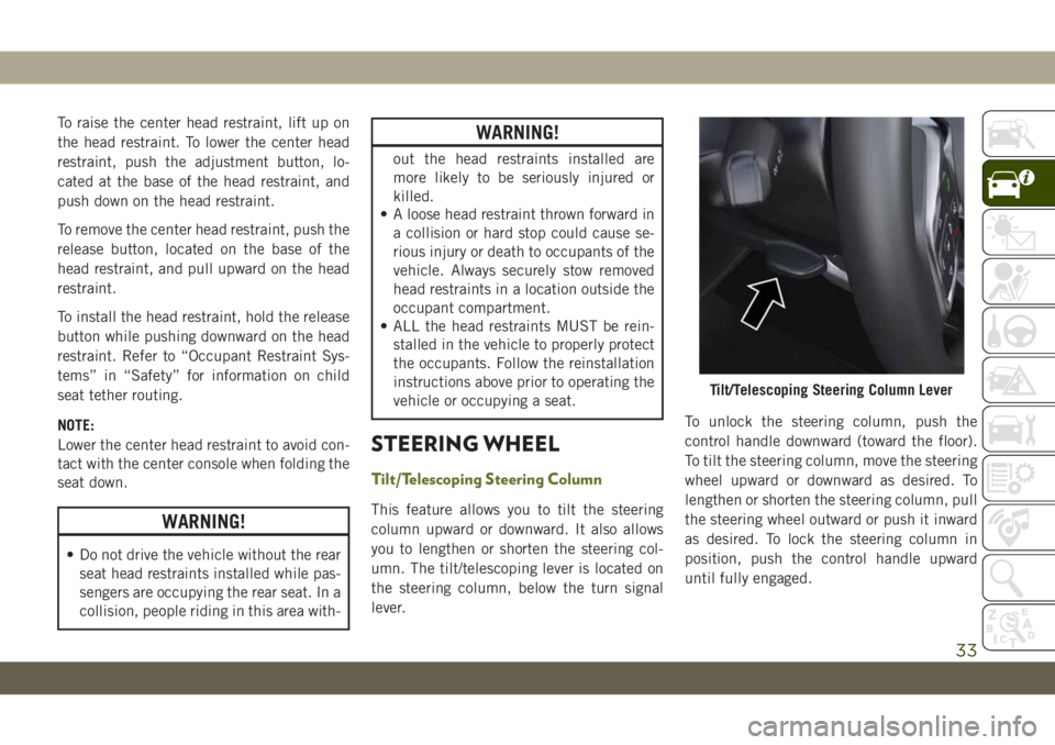
This feature allows you to tilt the steering
column upward or downward. It also allows
you to lengthen or shorten the steering col-
umn. The tilt/telescoping lever is located on
the steering column, below the turn signal
lever.To unlock the steering column, push the
control handle downward (toward the floor).
To tilt the steering column, move the steering
wheel upward or downward as desired. To
lengthen or shorten the steering column, pull
the steering wheel outward or push it inward
as desired. To lock the steering column in
position, push the control handle upward
until fully engaged.
Tilt/Telescoping Steering Column Lever
33
Page 36 of 348
WARNING!
Do not adjust the steering column while
driving. Adjusting the steering column
while driving or driving with the steering
column unlocked, could cause the driver
to lose control of the vehicle. Failure to
follow this warning may result in serious
injury or death.
Heated Steering Wheel — If Equipped
The steering wheel contains a heating ele-
ment that helps warm your hands in cold
weather. The heated steering wheel has only
one temperature setting. Once the heated
steering wheel has been turned on, it will stay
on until the operator turns it off. The heated
steering wheel may not turn on when it is
already warm.
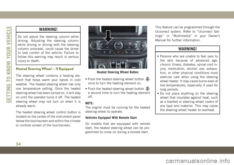
The heated steering wheel control button is
located on the center of the instrument panel
below the touchscreen and within the climate
or controls screen of the touchscreen.• Push the heated steering wheel button
once to turn the heating element on.
• Push the heated steering wheel button
a second time to turn the heating element
off.
NOTE:
The engine must be running for the heated
steering wheel to operate.
Vehicles Equipped With Remote Start
On models that are equipped with remote
start, the heated steering wheel can be pro-
grammed to come on during a remote start.This feature can be programmed through the
Uconnect system. Refer to “Uconnect Set-
tings” in “Multimedia” in your Owner’s
Manual for further information.
WARNING!
• Persons who are unable to feel pain to
the skin because of advanced age,
chronic illness, diabetes, spinal cord in-
jury, medication, alcohol use, exhaus-
tion, or other physical conditions must
exercise care when using the steering
wheel heater. It may cause burns even at
low temperatures, especially if used for
long periods.
• Do not place anything on the steering
wheel that insulates against heat, such
as a blanket or steering wheel covers of
any type and material. This may cause
the steering wheel heater to overheat.
Heated Steering Wheel Button
GETTING TO KNOW YOUR VEHICLE
34
Page 38 of 348
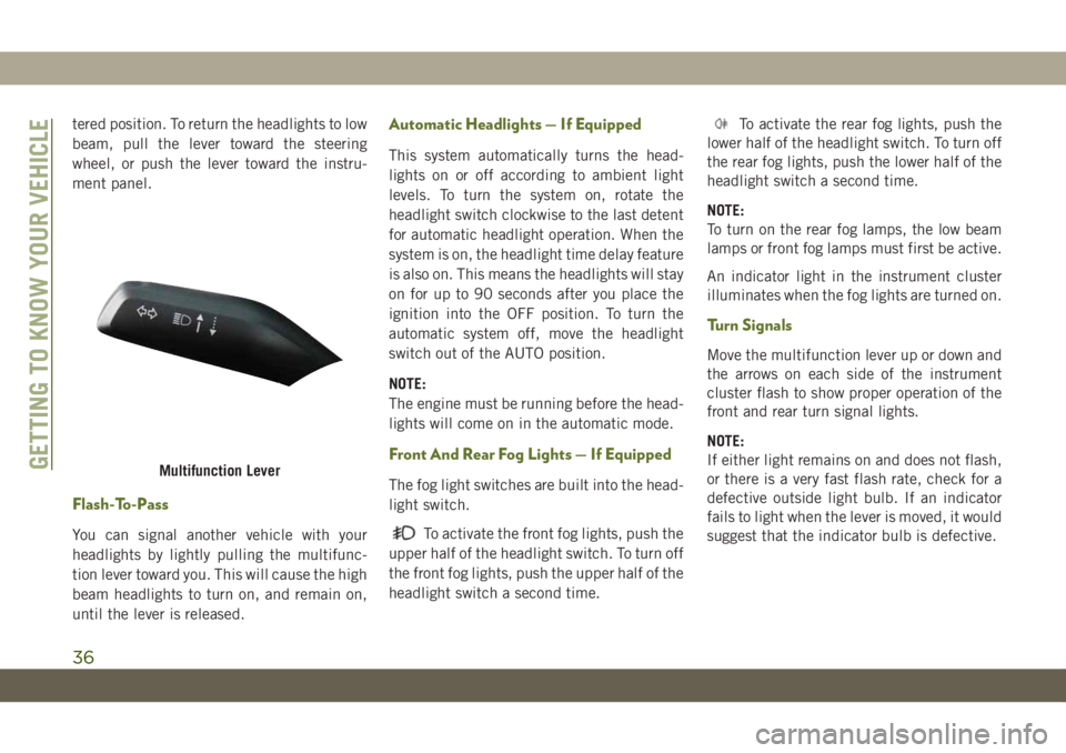
tered position. To return the headlights to low
beam, pull the lever toward the steering
wheel, or push the lever toward the instru-
ment panel.
Flash-To-Pass
You can signal another vehicle with your
headlights by lightly pulling the multifunc-
tion lever toward you. This will cause the high
beam headlights to turn on, and remain on,
until the lever is released.
Automatic Headlights — If Equipped
This system automatically turns the head-
lights on or off according to ambient light
levels. To turn the system on, rotate the
headlight switch clockwise to the last detent
for automatic headlight operation. When the
system is on, the headlight time delay feature
is also on. This means the headlights will stay
on for up to 90 seconds after you place the
ignition into the OFF position. To turn the
automatic system off, move the headlight
switch out of the AUTO position.
NOTE:
The engine must be running before the head-
lights will come on in the automatic mode.
Front And Rear Fog Lights — If Equipped
The fog light switches are built into the head-
light switch.
To activate the front fog lights, push the
upper half of the headlight switch. To turn off
the front fog lights, push the upper half of the
headlight switch a second time.
To activate the rear fog lights, push the
lower half of the headlight switch. To turn off
the rear fog lights, push the lower half of the
headlight switch a second time.
NOTE:
To turn on the rear fog lamps, the low beam
lamps or front fog lamps must first be active.
An indicator light in the instrument cluster
illuminates when the fog lights are turned on.
Turn Signals
Move the multifunction lever up or down and
the arrows on each side of the instrument
cluster flash to show proper operation of the
front and rear turn signal lights.
NOTE:
If either light remains on and does not flash,
or there is a very fast flash rate, check for a
defective outside light bulb. If an indicator
fails to light when the lever is moved, it would
suggest that the indicator bulb is defective.
Multifunction LeverGETTING TO KNOW YOUR VEHICLE
36
Page 39 of 348
Lane Change Assist — If Equipped
Tap the multifunction lever up or down once,
without moving beyond the detent, and the
turn signal (right or left) will flash three times
then automatically turn off.
Lights-On Reminder
If the headlights, parking lights, or cargo
lights are left on after the ignition is turned
OFF, a chime will sound when the driver’s
door is opened.
Headlight Leveling System — If Equipped
Your vehicle may be equipped with a head-
light leveling system. This system allows the
driver to maintain proper headlight beam
position with the road surface regardless of
vehicle load.
The control switch is located on the instru-
ment panel next to the dimmer control.
To operate, rotate the control switch until the
appropriate number, which corresponds to
the load listed on the chart, aligns with the
indicator line on the switch.
0/1Driver only, or driver and
front passenger.
2All seating positions occu-
pied, plus an evenly dis-
tributed load in the lug-
gage compartment. The
total weight of passengers
and load does not exceed
the maximum load capacity
of the vehicle.
3Driver, plus an evenly dis-
tributed load in the lug-
gage compartment. The
total weight of the driver
and load does not exceed
the maximum load capacity
of the vehicle.
WINDSHIELD WIPERS AND
WASHERS
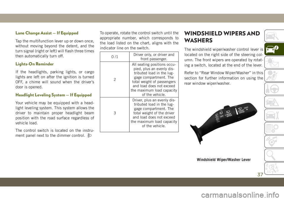
The windshield wiper/washer control lever is
located on the right side of the steering col-
umn. The front wipers are operated by rotat-
ing a switch, located at the end of the lever.
Refer to “Rear Window Wiper/Washer” in this
section for further information on using the
rear window wiper/washer.
Windshield Wiper/Washer Lever
37
Page 64 of 348
INSTRUMENT CLUSTER
DISPLAY
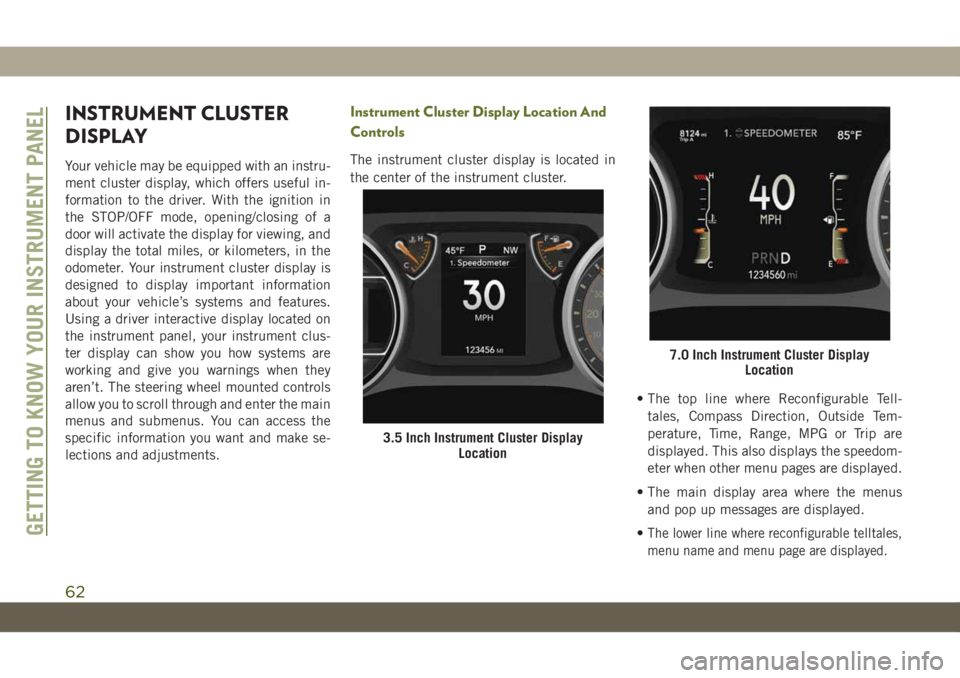
Your vehicle may be equipped with an instru-
ment cluster display, which offers useful in-
formation to the driver. With the ignition in
the STOP/OFF mode, opening/closing of a
door will activate the display for viewing, and
display the total miles, or kilometers, in the
odometer. Your instrument cluster display is
designed to display important information
about your vehicle’s systems and features.
Using a driver interactive display located on
the instrument panel, your instrument clus-
ter display can show you how systems are
working and give you warnings when they
aren’t. The steering wheel mounted controls
allow you to scroll through and enter the main
menus and submenus. You can access the
specific information you want and make se-
lections and adjustments.
Instrument Cluster Display Location And
Controls
The instrument cluster display is located in
the center of the instrument cluster.
• The top line where Reconfigurable Tell-
tales, Compass Direction, Outside Tem-
perature, Time, Range, MPG or Trip are
displayed. This also displays the speedom-
eter when other menu pages are displayed.
• The main display area where the menus
and pop up messages are displayed.
•
The lower line where reconfigurable telltales,
menu name and menu page are displayed.
3.5 Inch Instrument Cluster Display
Location
7.0 Inch Instrument Cluster Display
Location
GETTING TO KNOW YOUR INSTRUMENT PANEL
62
Page 70 of 348
— Battery Charge Warning Light
This warning light will illuminate when the
battery is not charging properly. If it stays on
while the engine is running, there may be a
malfunction with the charging system. Con-
tact an authorized dealer as soon as possible.
This indicates a possible problem with the
electrical system or a related component.
— Door Open Warning Light
This indicator will illuminate when a door is
ajar/open and not fully closed.
NOTE:
If the vehicle is moving, there will also be a
single chime.
— Electric Power Steering Fault
Warning Light
This warning light will turn on when there's a
fault with the EPS (Electric Power Steering)
system. Refer to “Power Steering” in “Start-
ing And Operating” in the Owner’s Manual for
further information.
WARNING!
Continued operation with reduced assist
could pose a safety risk to yourself and
others. Service should be obtained as soon
as possible.
— Electronic Throttle Control (ETC)
Warning Light
This warning light will illuminate to indicate
a problem with the Electronic Throttle Con-
trol (ETC) system. If a problem is detected
while the vehicle is running, the light will
either stay on or flash depending on the
nature of the problem. Cycle the ignition
when the vehicle is safely and completely
stopped and the transmission is placed in the
PARK position. The light should turn off. If
the light remains on with the vehicle running,
your vehicle will usually be drivable; however,
see an authorized dealer for service as soon
as possible.
NOTE:
This light may turn on if the accelerator and
brake pedals are pressed at the same time.If the light continues to flash when the ve-
hicle is running, immediate service is re-
quired and you may experience reduced per-
formance, an elevated/rough idle, or engine
stall and your vehicle may require towing.
The light will come on when the ignition is
placed in the ON/RUN or ACC/ON/RUN posi-
tion and remain on briefly as a bulb check. If
the light does not come on during starting,
have the system checked by an authorized
dealer.
— Engine Coolant Temperature Warn-
ing Light
This warning light warns of an overheated
engine condition. If the engine coolant tem-
perature is too high, this indicator will illumi-
nate and a single chime will sound. If the
temperature reaches the upper limit, a con-
tinuous chime will sound for four minutes or
until the engine is able to cool: whichever
comes first.
If the light turns on while driving, safely pull
over and stop the vehicle. If the A/C system is
on, turn it off. Also, shift the transmission
GETTING TO KNOW YOUR INSTRUMENT PANEL
68