tow JEEP WRANGLER UNLIMITED 2019 Owner handbook (in English)
[x] Cancel search | Manufacturer: JEEP, Model Year: 2019, Model line: WRANGLER UNLIMITED, Model: JEEP WRANGLER UNLIMITED 2019Pages: 348, PDF Size: 6.5 MB
Page 166 of 348
• When you turn ParkSense OFF, the instru-
ment cluster display will read
“PARKSENSE OFF.” Furthermore, once
you turn ParkSense OFF, it remains off until
you turn it on again, even if you cycle the
ignition.
• ParkSense, when on, will reduce the vol-
ume of the radio when it is sounding a tone.
• Clean the ParkSense sensors regularly, tak-
ing care not to scratch or damage them.
The sensors must not be covered with ice,
snow, slush, mud, dirt or debris. Failure to
do so can result in the system not working
properly. The ParkSense system might not
detect an obstacle behind the fascia/
bumper, or it could provide a false indica-
tion that an obstacle is behind the fascia/
bumper.
• Use the ParkSense switch to turn the
ParkSense system OFF if objects such as
bicycle carriers, trailer hitches, etc. are
placed within 12 inches (30 cm) from the
rear fascia/bumper. Failure to do so can
result in the system misinterpreting a close
object as a sensor problem, causing the“PARKSENSE UNAVAILABLE SERVICE
REQUIRED” message to be displayed in
the instrument cluster display.
• The operation of the rear sensors is auto-
matically deactivated when the trailer's
electric plug is inserted in the vehicle's tow
hook socket. The rear sensors are automati-
cally reactivated when the trailer's cable
plug is removed.
WARNING!
• Drivers must be careful when backing up
even when using ParkSense. Always
check carefully behind your vehicle,
look behind you, and be sure to check
for pedestrians, animals, other vehicles,
obstructions, and blind spots before
backing up. You are responsible for
safety and must continue to pay atten-
tion to your surroundings. Failure to do
so can result in serious injury or death.
• Before using ParkSense, it is strongly
recommended that the ball mount and
hitch ball assembly is disconnected
from the vehicle when the vehicle is not
used for towing. Failure to do so can
WARNING!
result in injury or damage to vehicles or
obstacles because the hitch ball will be
much closer to the obstacle than the
rear fascia when the loudspeaker sounds
the continuous tone. Also, the sensors
could detect the ball mount and hitch
ball assembly, depending on its size and
shape, giving a false indication that an
obstacle is behind the vehicle.
CAUTION!
• ParkSense is only a parking aid and it is
unable to recognize every obstacle, in-
cluding small obstacles. Parking curbs
might be temporarily detected or not
detected at all. Obstacles located above
or below the sensors will not be detected
when they are in close proximity.
• The vehicle must be driven slowly when
using ParkSense in order to be able to
stop in time when an obstacle is de-
tected. It is recommended that the
driver looks over his/her shoulder when
using ParkSense.STARTING AND OPERATING
164
Page 173 of 348

TRAILER TOWING
Trailer Towing Weights (Maximum Trailer Weight Ratings)
Model Frontal Area Max. GTW (Gross Trailer Wt.) Max. Trailer Tongue Wt. (See Note)
Two–Door 20 ft2 (1.86 m2) 3,300 lb (1,497 kg) 165 lb (75 kg)
Four–Door 30 ft2 (2.79 m2) 5,500 lbs (2,495 kg) 275 lbs (125 kg)
When towing a trailer the technically permissible laden weight may be exceeded by not more than 10% or 220 lbs (100 kg), whichever is lower
provided the operating speed is restricted to 62mph (100km/h) or less. Trailer sway control device is recommended when towing more than
1000 lbs (454 kg).
RECREATIONAL TOWING (BEHIND MOTORHOME, ETC.)
Towing This Vehicle Behind Another Vehicle
Towing Condition Wheels OFF the Ground Four-Wheel Drive Models
Flat Tow NONESee Instructions
•
Automatic transmission in PARK.
• Transfer case in NEUTRAL (N).
• Disconnect negative battery cable.
• Tow in forward direction.
Dolly TowFront NOT ALLOWED
Rear NOT ALLOWED
On Trailer ALL OK
NOTE:
When towing your vehicle, always follow applicable laws. Contact local authorities for additional details.
171
Page 174 of 348
Recreational Towing — Four-Wheel Drive
Models
NOTE:
The transfer case must be shifted into NEU-
TRAL (N), transmission must be in PARK, for
recreational towing.
CAUTION!
• DO NOT dolly tow any 4WD vehicle.
Towing with only one set of wheels on
the ground (front or rear) will cause
severe transmission and/or transfer case
damage. Tow with all four wheels either
ON the ground, or OFF the ground (using
a vehicle trailer).
• Tow only in the forward direction. Towing
this vehicle backwards can cause severe
damage to the transfer case.
• Automatic transmissions must be
placed in PARK for recreational towing.
• Before recreational towing, perform the
procedure outlined under “Shifting Into
NEUTRAL (N)” to be certain that the
transfer case is fully in NEUTRAL (N).
Otherwise, internal damage will result.
CAUTION!
• Towing this vehicle in violation of the
above requirements can cause severe
transmission and/or transfer case dam-
age. Damage from improper towing is
not covered under the New Vehicle Lim-
ited Warranty.
• Do not use a bumper-mounted clamp-on
tow bar on your vehicle. The bumper
face bar will be damaged.
Shifting Into NEUTRAL (N)
Use the following procedure to prepare your
vehicle for recreational towing.
WARNING!
You or others could be injured or killed if
you leave the vehicle unattended with the
transfer case in the NEUTRAL (N) position
without first fully engaging the parking
brake. The transfer case NEUTRAL (N)
position disengages both the front and rear
driveshafts from the powertrain, and will
allow the vehicle to roll, even if the auto-
matic transmission is in PARK. The park-
WARNING!
ing brake should always be applied when
the driver is not in the vehicle.
CAUTION!
It is necessary to follow these steps to be
certain that the transfer case is fully in
NEUTRAL (N) before recreational towing
to prevent damage to internal parts.
1. Bring the vehicle to a complete stop on
level ground.
2. Press and hold the brake pedal.
3. Shift the transmission into NEUTRAL.
4. Turn the engine OFF.
5. Shift the transfer case lever into NEU-
TRAL (N).
6. Start the engine.
7. Shift the transmission into REVERSE.
8. Release the brake pedal for five seconds
and ensure that there is no vehicle
movement.
STARTING AND OPERATING
172
Page 175 of 348
9. Repeat steps seven and eight with the
transmission in DRIVE.
10. Turn the engine OFF and leave the igni-
tion in the unlocked ACC position.
11. Firmly apply the parking brake.
12. Shift the transmission into PARK (NOT
in NEUTRAL).
CAUTION!
Damage to the transmission may occur if
the transmission is shifted into PARK with
the transfer case in NEUTRAL (N) and the
engine running. With the transfer case in
NEUTRAL (N) ensure that the engine is
OFF before shifting the transmission into
PARK.13. Attach the vehicle to the tow vehicle
using a suitable tow bar.
14. Release the parking brake.
15. Disconnect the negative battery cable,
and secure it away from the negative
battery post.
Shifting Out of NEUTRAL (N)
Use the following procedure to prepare your
vehicle for normal usage.
1. Bring the vehicle to a complete stop, leav-
ing it connected to the tow vehicle.
2. Firmly apply the parking brake.
3. Reconnect the negative battery cable.
4. Start the engine.
5. Press and hold the brake pedal.
6. Shift the transmission into NEUTRAL.7. Turn the engine OFF.
8. Shift the transfer case lever to the desired
position.
NOTE:
When shifting the transfer case out of
NEUTRAL (N), the engine should remain
OFF to avoid gear clash.
9. Shift the transmission into PARK.
10. Release the brake pedal.
11. Disconnect vehicle from the tow vehicle.
12. Start the engine.
13. Press and hold the brake pedal.
14. Release the parking brake.
15. Shift the transmission into gear, release
the brake pedal, and check that the
vehicle operates normally.
173
Page 177 of 348
IN CASE OF EMERGENCY
HAZARD WARNING FLASHERS .176
BULB REPLACEMENT........176
Replacement Bulbs............176
Bulb Replacement.............178
FUSES...................180
General Information.............181
Power Distribution Center (PDC).....181
JACKING AND TIRE CHANGING. .189
Jack Location................190
Spare Tire Removal.............190Preparations For Jacking.........191
Jacking Instructions............191
Road Tire Installation............194
Declaration Of Conformance.......194
Jack Usage Precautions..........196
JUMP STARTING............196
Preparations For Jump Start........197
Jump Starting Procedure..........198
IF YOUR ENGINE OVERHEATS . .199
MANUAL PARK RELEASE.....200FREEING A STUCK VEHICLE . . .201
TOWING A DISABLED VEHICLE.202
Without The Key Fob............203
Four–Wheel Drive Models.........203
Tow Eye Usage................203
ENHANCED ACCIDENT RESPONSE
SYSTEM (EARS)............205
EVENT DATA RECORDER
(EDR)....................205
IN CASE OF EMERGENCY
175
Page 180 of 348
Bulb Replacement
NOTE:
Lens fogging can occur under certain atmo-
spheric conditions. This will usually clear as
atmospheric conditions change to allow the
condensation to change back into a vapor.
Turning the lamps on will usually accelerate
the clearing process.
Halogen Headlamps
NOTE:
We advise referring to an authorized dealer
for service.
1. Open hood and support using prop rod.
2. Remove the front grille. Turn the retainers
along the top 1/4 turn counterclockwise
and remove.
3. Pull the bottom of the grille away starting
at one side and working toward the other.
4. Remove the three screws holding the
headlamp to the vehicle.
5. Remove lamp from the vehicle.
6. Remove the lamp from the collar.7. Grasp the bulb and turn 1/4 turn
counterclockwise.
8. Pull the bulb from the housing.
9. Push connector locking tab to the unlock
position.
10. Remove connector from bulb.
11. Push connector onto new bulb base, and
push the connector locking tab to the
lock position.CAUTION!
Do not touch the new bulb with your fin-
gers. Oil contamination will severely
shorten bulb life. If the bulb comes in
contact with any oily surface, clean the
bulb with rubbing alcohol.
12. Reinstall bulb housing. Rotate the bulb
1/4 turn clockwise.
Front Park/Turn Signal
NOTE:
We advise referring to an authorized dealer
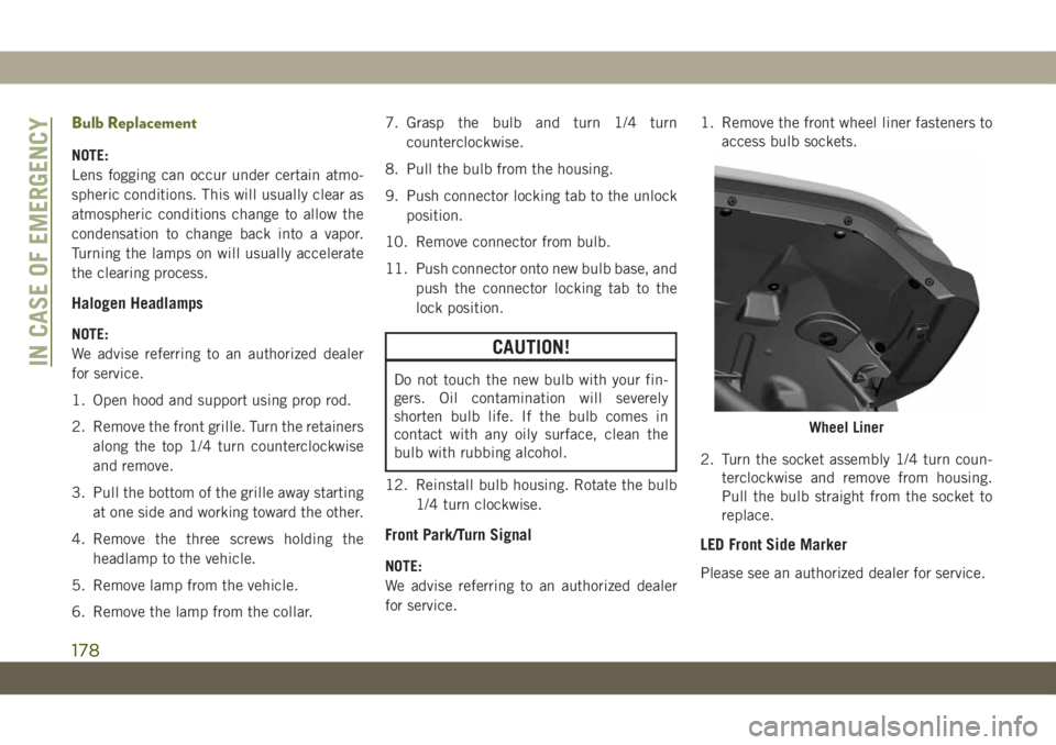
for service.1. Remove the front wheel liner fasteners to
access bulb sockets.
2. Turn the socket assembly 1/4 turn coun-
terclockwise and remove from housing.
Pull the bulb straight from the socket to
replace.
LED Front Side Marker
Please see an authorized dealer for service.
Wheel Liner
IN CASE OF EMERGENCY
178
Page 186 of 348
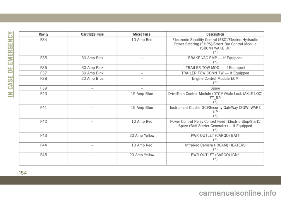
Cavity Cartridge Fuse Micro Fuse Description
F34 – 10 Amp Red Electronic Stability Control (ESC)/Electric Hydraulic
Power Steering (EHPS)/Smart Bar Control Module
(SBCM) WAKE UP
(*)
F35 30 Amp Pink – BRAKE VAC PMP — If Equipped
(*)
F36 30 Amp Pink – TRAILER TOW MOD — If Equipped
F37 30 Amp Pink – TRAILER TOW CONN 7W — If Equipped
F38 20 Amp Blue – Engine Control Module ECM
(*)
F39 – – Spare
F40 – 15 Amp Blue DriveTrain Control Module (DTCM)/Axle Lock (AXLE LOC)
FT_RR
(*)
F41 – 15 Amp Blue Instrument Cluster (IC)/Security GateWay (SGW) WAKE
UP
(*)
F42 – 10 Amp Red Power Control Relay Control Feed (Electric Stop/Start)/
Spare (Belt Starter Generator) -- If Equipped
(*)
F43 20 Amp Yellow PWR OUTLET (CARGO) BATT
(*)
F44 – 10 Amp Red InfraRed Camera (IRCAM) HEATERS
(*)
F45 – 20 Amp Yellow PWR OUTLET (CARGO) IGN*
(*)
IN CASE OF EMERGENCY
184
Page 190 of 348
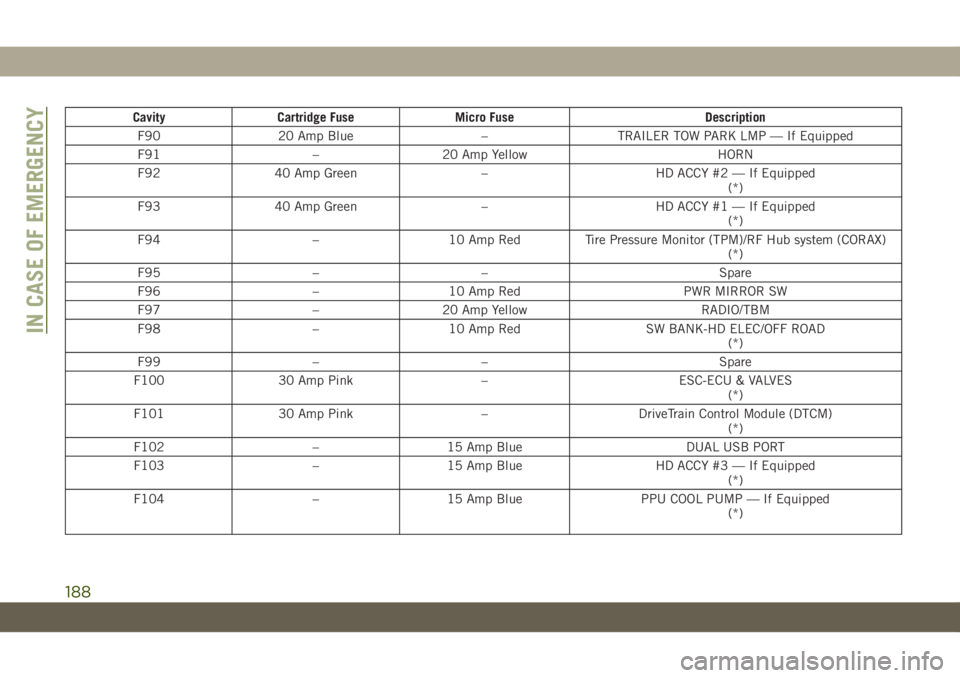
Cavity Cartridge Fuse Micro Fuse Description
F90 20 Amp Blue – TRAILER TOW PARK LMP — If Equipped
F91 – 20 Amp Yellow HORN
F92 40 Amp Green – HD ACCY #2 — If Equipped
(*)
F93 40 Amp Green – HD ACCY #1 — If Equipped
(*)
F94 – 10 Amp Red Tire Pressure Monitor (TPM)/RF Hub system (CORAX)
(*)
F95 – – Spare
F96 – 10 Amp Red PWR MIRROR SW
F97 – 20 Amp Yellow RADIO/TBM
F98 – 10 Amp Red SW BANK-HD ELEC/OFF ROAD
(*)
F99 – – Spare
F100 30 Amp Pink – ESC-ECU & VALVES
(*)
F101 30 Amp Pink – DriveTrain Control Module (DTCM)
(*)
F102 – 15 Amp Blue DUAL USB PORT
F103 – 15 Amp Blue HD ACCY #3 — If Equipped
(*)
F104 – 15 Amp Blue PPU COOL PUMP — If Equipped
(*)
IN CASE OF EMERGENCY
188
Page 191 of 348
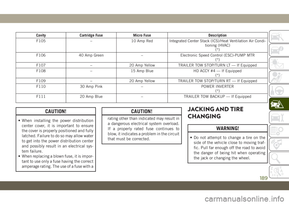
Cavity Cartridge Fuse Micro Fuse Description
F105 – 10 Amp Red Integrated Center Stack (ICS)/Heat Ventilation Air Condi-
tioning (HVAC)
(*)
F106 40 Amp Green – Electronic Speed Control (ESC)-PUMP MTR
(*)
F107 – 20 Amp Yellow TRAILER TOW STOP/TURN LT — If Equipped
F108 – 15 Amp Blue HD ACCY #4 — If Equipped
(*)
F109 – 20 Amp Yellow TRAILER TOW STOP/TURN RT — If Equipped
F110 30 Amp Pink – POWER INVERTER
(*)
F111 20 Amp Blue – TRAILER TOW BACKUP — If Equipped
CAUTION!
• When installing the power distribution
center cover, it is important to ensure
the cover is properly positioned and fully
latched. Failure to do so may allow water
to get into the power distribution center
and possibly result in an electrical sys-
tem failure.
• When replacing a blown fuse, it is impor-
tant to use only a fuse having the correct
amperage rating. The use of a fuse with a
CAUTION!
rating other than indicated may result in
a dangerous electrical system overload.
If a properly rated fuse continues to
blow, it indicates a problem in the circuit
that must be corrected.
JACKING AND TIRE
CHANGING
WARNING!
• Do not attempt to change a tire on the
side of the vehicle close to moving traf-
fic. Pull far enough off the road to avoid
the danger of being hit when operating
the jack or changing the wheel.
189
Page 192 of 348
WARNING!
• Being under a jacked-up vehicle is dan-
gerous. The vehicle could slip off the
jack and fall on you. You could be
crushed. Never put any part of your body
under a vehicle that is on a jack. If you
need to get under a raised vehicle, take
it to a service center where it can be
raised on a lift.
• Never start or run the engine while the
vehicle is on a jack.
• The jack is designed to be used as a tool
for changing tires only. The jack should
not be used to lift the vehicle for service
purposes. The vehicle should be jacked
on a firm level surface only. Avoid ice or
slippery areas.
Jack Location
The jack and lug wrench are located in the
rear cargo area. To remove jack and tools
proceed as follows:
1. Lift the load floor in the cargo area.NOTE:
The load floor can be removed for easier
access by pulling the load floor directly
rearward.
2. Remove the hardware storage cover by
pinching the latch on the left side and
pulling upward.
3. Turn the black plastic wing nut counter-
clockwise to loosen the jack from the
storage bin.
4. Remove tool kit and assemble tools.
Spare Tire Removal
1. To remove the spare tire from the carrier,
remove the tire cover, if equipped.
NOTE:
The spare wheel is mounted on the out-
side of the tailgate, protected by a plastic
cover with fasteners. Under traffic regula-
tions, the cover must not be removed or
insecurely fixed during use of the vehicle
on the public highway. Reference should
be made to local laws and regulations. Ifthe spare wheel is used, before continuing
your journey check that the damaged
wheel is securely mounted and the cover
is correctly fixed in place. Also take care
not to obstruct the rear camera.
2. Remove the Rear Camera Cover by turning
the lock bolt to the left with the #T40 Torx
head driver and ratchet from the supplied
tool kit.
3. Remove the lug nuts with the lug wrench
turning them counterclockwise. If
equipped, remove the locking lug nut with
the lock key (located in the glove box)
turning it counterclockwise.
Stowing The Replaced Spare Tire
1. Mount the spare tire onto the carrier.
Torque down lug nuts and locking lug nut.
2. Return the lock bolt to the lock position
on the camera cover by turning the lock to
the right using the provided #T40 Torx
head driver and ratchet. Then, reinstall
the camera cover by slipping it over the
camera/tire carrier until it snaps into
place.
IN CASE OF EMERGENCY
190