engine JEEP WRANGLER UNLIMITED 2019 Owner handbook (in English)
[x] Cancel search | Manufacturer: JEEP, Model Year: 2019, Model line: WRANGLER UNLIMITED, Model: JEEP WRANGLER UNLIMITED 2019Pages: 348, PDF Size: 6.5 MB
Page 171 of 348
“Fluids and lubricants” in the “Technical
specifications” section. The vehicle is
equipped with an automatic AdBlue heating
system when the engine starts allowing the
system to work correctly at temperatures
lower than 12 °F (-11 °C).
NOTE:
AdBlue freezes at temperatures lower than
12 °F (-11 °C).
AdBlue (UREA) Storage
AdBlue (UREA) is considered a very stable
product with a long shelf life. If AdBlue
(UREA) is kept in temperatures between
10° and 90°F (-12° and 32°C), it will last a
minimum of one year.
AdBlue (UREA) is subject to freezing at the
lowest temperatures. For example, AdBlue
(UREA) may freeze at temperatures at or
below 12° F (-11° C). The system has been
designed to operate in this environment.NOTE:
When working with AdBlue (UREA), it is
important to know that:
• Any containers or parts that come into con-
tact with AdBlue (UREA) must be AdBlue
(UREA) compatible (plastic or stainless
steel). Copper, brass, aluminum, iron or
non-stainless steel should be avoided as
they are subject to corrosion by AdBlue
(UREA).
• If AdBlue (UREA) is spilled, it should be
wiped up completely.
Adding AdBlue (UREA)
Preliminary Conditions
AdBlue (UREA) freezes at temperatures
lower than 12° F (-11° C). If the car stands for
a long time at this temperature refilling could
be difficult. For this reason, it is advised to
park the vehicle in a garage and/or heated
environment and wait for the urea to return to
liquid state before topping up.
Proceed as follows:
• Park the car on flat ground and stop the
engine by cycling the ignition to the OFF
position.• Open the fuel door, undo and remove the
cap (blue) from the AdBlue (UREA) filler.
Refilling With Nozzles
You can fill up at any AdBlue (UREA) dis-
tributor.
Proceed as follows:
• Insert the AdBlue (UREA) nozzle in the
filler, start refilling and stop refilling at the
first shut-off (the shut-off indicates that the
AdBlue (UREA) tank is full). Do not pro-
ceed with the refilling, to prevent spillage
of AdBlue (UREA).
• Extract the nozzle.
Refilling With Containers
Proceed as follows:
• Check the expiration date.
• Read the advice for use on the label before
pouring the content of the bottle into the
AdBlue (UREA) tank.
• If systems which cannot be screwed in (e.g.
tanks) are used for refilling, after the indi-
cation appears on the instrument panel
display refer to “Warning lights And Mes-
sages" in the “Getting To Know Your Instru-
169
Page 172 of 348
ment Panel” for further information, fill the
AdBlue (UREA) tank with no more than
2 Gallons (8 liters).
• If containers which can be screwed to the
filler are used, the reservoir is full when the
AdBlue (UREA) level in the container stops
pouring out. Do not proceed further.
Operations After Refilling
Proceed as follows:
• Fit the cap back on the AdBlue (UREA)
filler by turning it clockwise and screwing it
completely.
• Cycle the ignition to RUN (it is not neces-
sary to start the engine).
• Wait for the indication on the instrument
panel to switch off before moving the car.
The indication may stay on for a few sec-
onds to approximately half a minute. If the
engine is started and the car is moved, the
indication will remain on for longer. This
will not compromise engine operation.• If the AdBlue (UREA) was topped up when
the tank was empty, wait for 2 minutes
before starting the engine.
NOTE:
• If AdBlue (UREA) is spilled out of the filler
neck, clean up well the area and proceed to
filling up again. If the liquid crystallizes,
eliminate it with a sponge and warm water.
• DO NOT EXCEED THE MAXIMUM LEVEL:
this could cause damage to the reservoir.
AdBlue (UREA) freezes at under 12° F
(-11° C). Although the system is designed
to operate below the freezing point of the
UREA, it is advisable not to fill the tank
beyond the maximum level because if the
UREA freezes the system can be damaged.
Follow the instructions in this section.
• If the AdBlue (UREA) is spilled on painted
surfaces or aluminium, immediately clean
the area with water and use absorbent ma-
terial to collect the fluid that has been
spilled on the ground.• Do not try to start the engine if AdBlue
(UREA) was accidentally added to the die-
sel fuel tank, this can result in serious
engine damage, contact an authorized
dealer.
• Do not add additives or other fluids to
AdBlue (UREA), doing so could damage the
system.
• The use of non-conforming or degraded
AdBlue (UREA) may lead to indications
appearing on the instrument panel display
refer to “Warning Lights And Messages" in
the “Getting To Know Your Instrument
Panel” for further information.
• Never pour AdBlue (UREA) into another
container: it could be contaminated.
• If the AdBlue (UREA) runs out, see refer to
“Warning Lights And Messages" in the
“Getting To Know Your Instrument Panel”
for further information to continue using
the car normally.
STARTING AND OPERATING
170
Page 174 of 348
Recreational Towing — Four-Wheel Drive
Models
NOTE:
The transfer case must be shifted into NEU-
TRAL (N), transmission must be in PARK, for
recreational towing.
CAUTION!
• DO NOT dolly tow any 4WD vehicle.
Towing with only one set of wheels on
the ground (front or rear) will cause
severe transmission and/or transfer case
damage. Tow with all four wheels either
ON the ground, or OFF the ground (using
a vehicle trailer).
• Tow only in the forward direction. Towing
this vehicle backwards can cause severe
damage to the transfer case.
• Automatic transmissions must be
placed in PARK for recreational towing.
• Before recreational towing, perform the
procedure outlined under “Shifting Into
NEUTRAL (N)” to be certain that the
transfer case is fully in NEUTRAL (N).
Otherwise, internal damage will result.
CAUTION!
• Towing this vehicle in violation of the
above requirements can cause severe
transmission and/or transfer case dam-
age. Damage from improper towing is
not covered under the New Vehicle Lim-
ited Warranty.
• Do not use a bumper-mounted clamp-on
tow bar on your vehicle. The bumper
face bar will be damaged.
Shifting Into NEUTRAL (N)
Use the following procedure to prepare your
vehicle for recreational towing.
WARNING!
You or others could be injured or killed if
you leave the vehicle unattended with the
transfer case in the NEUTRAL (N) position
without first fully engaging the parking
brake. The transfer case NEUTRAL (N)
position disengages both the front and rear
driveshafts from the powertrain, and will
allow the vehicle to roll, even if the auto-
matic transmission is in PARK. The park-
WARNING!
ing brake should always be applied when
the driver is not in the vehicle.
CAUTION!
It is necessary to follow these steps to be
certain that the transfer case is fully in
NEUTRAL (N) before recreational towing
to prevent damage to internal parts.
1. Bring the vehicle to a complete stop on
level ground.
2. Press and hold the brake pedal.
3. Shift the transmission into NEUTRAL.
4. Turn the engine OFF.
5. Shift the transfer case lever into NEU-
TRAL (N).
6. Start the engine.
7. Shift the transmission into REVERSE.
8. Release the brake pedal for five seconds
and ensure that there is no vehicle
movement.
STARTING AND OPERATING
172
Page 175 of 348
9. Repeat steps seven and eight with the
transmission in DRIVE.
10. Turn the engine OFF and leave the igni-
tion in the unlocked ACC position.
11. Firmly apply the parking brake.
12. Shift the transmission into PARK (NOT
in NEUTRAL).
CAUTION!
Damage to the transmission may occur if
the transmission is shifted into PARK with
the transfer case in NEUTRAL (N) and the
engine running. With the transfer case in
NEUTRAL (N) ensure that the engine is
OFF before shifting the transmission into
PARK.13. Attach the vehicle to the tow vehicle
using a suitable tow bar.
14. Release the parking brake.
15. Disconnect the negative battery cable,
and secure it away from the negative
battery post.
Shifting Out of NEUTRAL (N)
Use the following procedure to prepare your
vehicle for normal usage.
1. Bring the vehicle to a complete stop, leav-
ing it connected to the tow vehicle.
2. Firmly apply the parking brake.
3. Reconnect the negative battery cable.
4. Start the engine.
5. Press and hold the brake pedal.
6. Shift the transmission into NEUTRAL.7. Turn the engine OFF.
8. Shift the transfer case lever to the desired
position.
NOTE:
When shifting the transfer case out of
NEUTRAL (N), the engine should remain
OFF to avoid gear clash.
9. Shift the transmission into PARK.
10. Release the brake pedal.
11. Disconnect vehicle from the tow vehicle.
12. Start the engine.
13. Press and hold the brake pedal.
14. Release the parking brake.
15. Shift the transmission into gear, release
the brake pedal, and check that the
vehicle operates normally.
173
Page 177 of 348
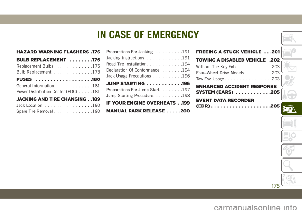
IN CASE OF EMERGENCY
HAZARD WARNING FLASHERS .176
BULB REPLACEMENT........176
Replacement Bulbs............176
Bulb Replacement.............178
FUSES...................180
General Information.............181
Power Distribution Center (PDC).....181
JACKING AND TIRE CHANGING. .189
Jack Location................190
Spare Tire Removal.............190Preparations For Jacking.........191
Jacking Instructions............191
Road Tire Installation............194
Declaration Of Conformance.......194
Jack Usage Precautions..........196
JUMP STARTING............196
Preparations For Jump Start........197
Jump Starting Procedure..........198
IF YOUR ENGINE OVERHEATS . .199
MANUAL PARK RELEASE.....200FREEING A STUCK VEHICLE . . .201
TOWING A DISABLED VEHICLE.202
Without The Key Fob............203
Four–Wheel Drive Models.........203
Tow Eye Usage................203
ENHANCED ACCIDENT RESPONSE
SYSTEM (EARS)............205
EVENT DATA RECORDER
(EDR)....................205
IN CASE OF EMERGENCY
175
Page 183 of 348
WARNING!
services are switched off and/or disen-
gaged.
• If the replaced fuse blows again, contact
an authorized dealer.
• If a general protection fuse for safety
systems (air bag system, braking sys-
tem), power unit systems (engine sys-
tem, gearbox system) or steering system
blows, contact an authorized dealer.
CAUTION!
If it is necessary to wash the engine com-
partment, take care not to directly hit the
CAUTION!
fuse box, and the windshield wiper motors
with water.
General Information
The fuses protect electrical systems against
excessive current.
When a device does not work, you must check
the fuse element inside the blade fuse for a
break/melt.
Also, please be aware that when using power
outlets for extended periods of time with the
engine off may result in vehicle battery dis-
charge.
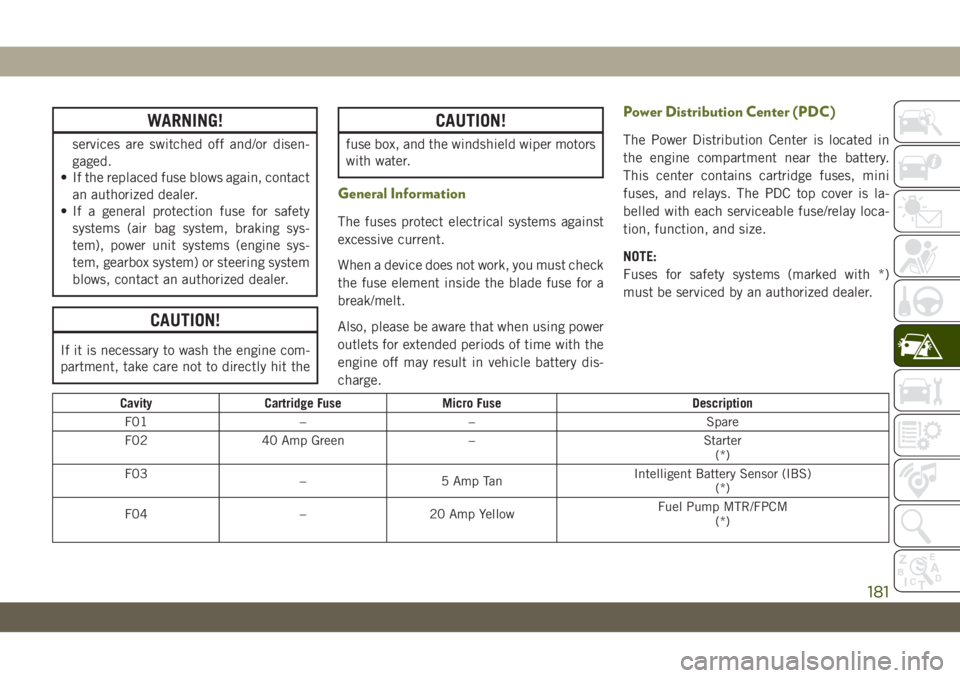
Power Distribution Center (PDC)
The Power Distribution Center is located in
the engine compartment near the battery.
This center contains cartridge fuses, mini
fuses, and relays. The PDC top cover is la-
belled with each serviceable fuse/relay loca-
tion, function, and size.
NOTE:
Fuses for safety systems (marked with *)
must be serviced by an authorized dealer.
Cavity Cartridge Fuse Micro Fuse Description
F01 – – Spare
F02 40 Amp Green – Starter
(*)
F03
– 5 Amp TanIntelligent Battery Sensor (IBS)
(*)
F04 – 20 Amp YellowFuel Pump MTR/FPCM
(*)
181
Page 185 of 348
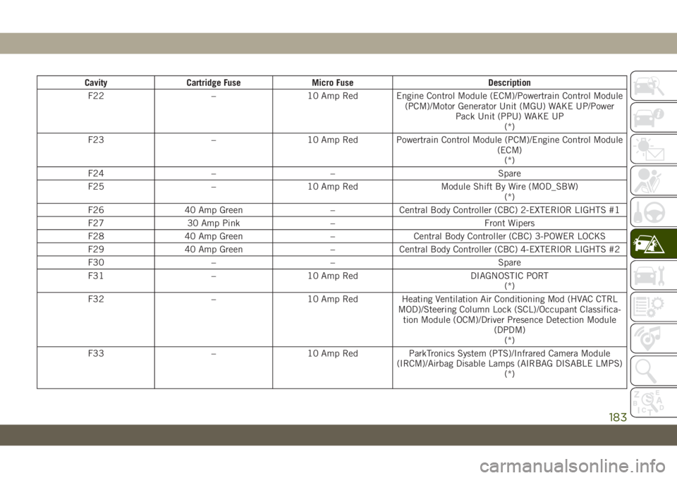
Cavity Cartridge Fuse Micro Fuse Description
F22 – 10 Amp Red Engine Control Module (ECM)/Powertrain Control Module
(PCM)/Motor Generator Unit (MGU) WAKE UP/Power
Pack Unit (PPU) WAKE UP
(*)
F23 – 10 Amp Red Powertrain Control Module (PCM)/Engine Control Module
(ECM)
(*)
F24 – – Spare
F25 – 10 Amp Red Module Shift By Wire (MOD_SBW)
(*)
F26 40 Amp Green – Central Body Controller (CBC) 2-EXTERIOR LIGHTS #1
F27 30 Amp Pink – Front Wipers
F28 40 Amp Green – Central Body Controller (CBC) 3-POWER LOCKS
F29 40 Amp Green – Central Body Controller (CBC) 4-EXTERIOR LIGHTS #2
F30 – – Spare
F31 – 10 Amp Red DIAGNOSTIC PORT
(*)
F32 – 10 Amp Red Heating Ventilation Air Conditioning Mod (HVAC CTRL
MOD)/Steering Column Lock (SCL)/Occupant Classifica-
tion Module (OCM)/Driver Presence Detection Module
(DPDM)
(*)
F33 – 10 Amp Red ParkTronics System (PTS)/Infrared Camera Module
(IRCM)/Airbag Disable Lamps (AIRBAG DISABLE LMPS)
(*)
183
Page 186 of 348
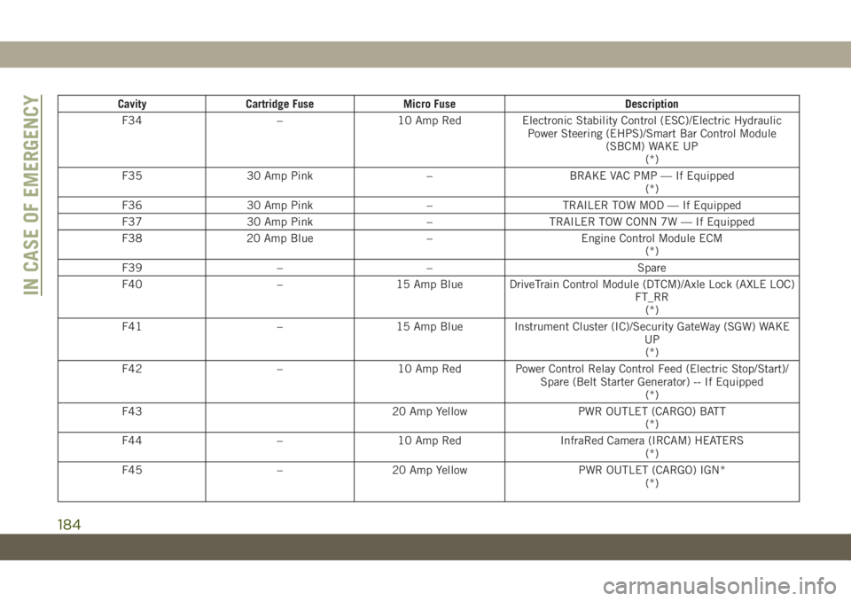
Cavity Cartridge Fuse Micro Fuse Description
F34 – 10 Amp Red Electronic Stability Control (ESC)/Electric Hydraulic
Power Steering (EHPS)/Smart Bar Control Module
(SBCM) WAKE UP
(*)
F35 30 Amp Pink – BRAKE VAC PMP — If Equipped
(*)
F36 30 Amp Pink – TRAILER TOW MOD — If Equipped
F37 30 Amp Pink – TRAILER TOW CONN 7W — If Equipped
F38 20 Amp Blue – Engine Control Module ECM
(*)
F39 – – Spare
F40 – 15 Amp Blue DriveTrain Control Module (DTCM)/Axle Lock (AXLE LOC)
FT_RR
(*)
F41 – 15 Amp Blue Instrument Cluster (IC)/Security GateWay (SGW) WAKE
UP
(*)
F42 – 10 Amp Red Power Control Relay Control Feed (Electric Stop/Start)/
Spare (Belt Starter Generator) -- If Equipped
(*)
F43 20 Amp Yellow PWR OUTLET (CARGO) BATT
(*)
F44 – 10 Amp Red InfraRed Camera (IRCAM) HEATERS
(*)
F45 – 20 Amp Yellow PWR OUTLET (CARGO) IGN*
(*)
IN CASE OF EMERGENCY
184
Page 192 of 348
WARNING!
• Being under a jacked-up vehicle is dan-
gerous. The vehicle could slip off the
jack and fall on you. You could be
crushed. Never put any part of your body
under a vehicle that is on a jack. If you
need to get under a raised vehicle, take
it to a service center where it can be
raised on a lift.
• Never start or run the engine while the
vehicle is on a jack.
• The jack is designed to be used as a tool
for changing tires only. The jack should
not be used to lift the vehicle for service
purposes. The vehicle should be jacked
on a firm level surface only. Avoid ice or
slippery areas.
Jack Location
The jack and lug wrench are located in the
rear cargo area. To remove jack and tools
proceed as follows:
1. Lift the load floor in the cargo area.NOTE:
The load floor can be removed for easier
access by pulling the load floor directly
rearward.
2. Remove the hardware storage cover by
pinching the latch on the left side and
pulling upward.
3. Turn the black plastic wing nut counter-
clockwise to loosen the jack from the
storage bin.
4. Remove tool kit and assemble tools.
Spare Tire Removal
1. To remove the spare tire from the carrier,
remove the tire cover, if equipped.
NOTE:
The spare wheel is mounted on the out-
side of the tailgate, protected by a plastic
cover with fasteners. Under traffic regula-
tions, the cover must not be removed or
insecurely fixed during use of the vehicle
on the public highway. Reference should
be made to local laws and regulations. Ifthe spare wheel is used, before continuing
your journey check that the damaged
wheel is securely mounted and the cover
is correctly fixed in place. Also take care
not to obstruct the rear camera.
2. Remove the Rear Camera Cover by turning
the lock bolt to the left with the #T40 Torx
head driver and ratchet from the supplied
tool kit.
3. Remove the lug nuts with the lug wrench
turning them counterclockwise. If
equipped, remove the locking lug nut with
the lock key (located in the glove box)
turning it counterclockwise.
Stowing The Replaced Spare Tire
1. Mount the spare tire onto the carrier.
Torque down lug nuts and locking lug nut.
2. Return the lock bolt to the lock position
on the camera cover by turning the lock to
the right using the provided #T40 Torx
head driver and ratchet. Then, reinstall
the camera cover by slipping it over the
camera/tire carrier until it snaps into
place.
IN CASE OF EMERGENCY
190
Page 193 of 348
3. Reinstall the tire cover if applicable.
NOTE:
If you have added aftermarket accessories to
the spare tire mounted carrier, it cannot ex-
ceed a gross weight of 85 lbs (38.5 kg)
including the weight of the spare tire.
Preparations For Jacking
1. Park on a firm, level surface. Avoid ice or
slippery areas.
WARNING!
Do not attempt to change a tire on the side
of the vehicle close to moving traffic. Pull
far enough off the road to avoid being hit
when operating the jack or changing the
wheel.
2. Turn on the Hazard Warning flasher.
3. Apply the parking brake.
4. Shift the automatic transmission into
PARK.
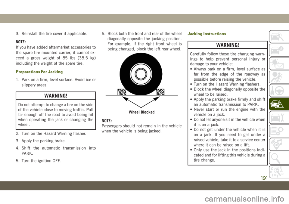
5. Turn the ignition OFF.6. Block both the front and rear of the wheel
diagonally opposite the jacking position.
For example, if the right front wheel is
being changed, block the left rear wheel.
NOTE:
Passengers should not remain in the vehicle
when the vehicle is being jacked.
Jacking Instructions
WARNING!
Carefully follow these tire changing warn-
ings to help prevent personal injury or
damage to your vehicle:
• Always park on a firm, level surface as
far from the edge of the roadway as
possible before raising the vehicle.
• Turn on the Hazard Warning flashers.
• Block the wheel diagonally opposite the
wheel to be raised.
• Apply the parking brake firmly and shift
an automatic transmission to PARK.
• Never start or run the engine with the
vehicle on a jack.
• Do not let anyone sit in the vehicle when
it is on a jack.
• Do not get under the vehicle when it is
on a jack. If you need to get under a
raised vehicle, take it to a service center
where it can be raised on a lift.
• Only use the jack in the positions indi-
cated and for lifting this vehicle during a
tire change.
Wheel Blocked
191