torque JEEP WRANGLER UNLIMITED 2019 Owner handbook (in English)
[x] Cancel search | Manufacturer: JEEP, Model Year: 2019, Model line: WRANGLER UNLIMITED, Model: JEEP WRANGLER UNLIMITED 2019Pages: 348, PDF Size: 6.5 MB
Page 25 of 348
WARNING!
• All occupants must wear seat belts dur-
ing off-road operation with doors re-
moved. Refer to “Off-Road Driving Tips”
in “Starting And Operating” in the Own-
er’s Manual for further information.
• Do not store detached doors inside of the
vehicle, as they may cause personal in-
jury in the event of an accident.
NOTE:
•Doors are heavy; use caution when removing
them.
•Hinge pin can break if overtightened during
door reinstall (Max Torque: 7.5 ft· lb /
10 N·m). Refer to “Off-Road Driving Tips” in
“Starting And Operating” in the Owner’s
Manual for further information.
1. Roll down the glass window to prevent any
damage.2. Remove the hinge pin screws from the
upper and lower outside hinges (using a
#T50 Torx head driver).
NOTE:
The hinge pin screws and nuts can be
stowed in the rear cargo tray located un-
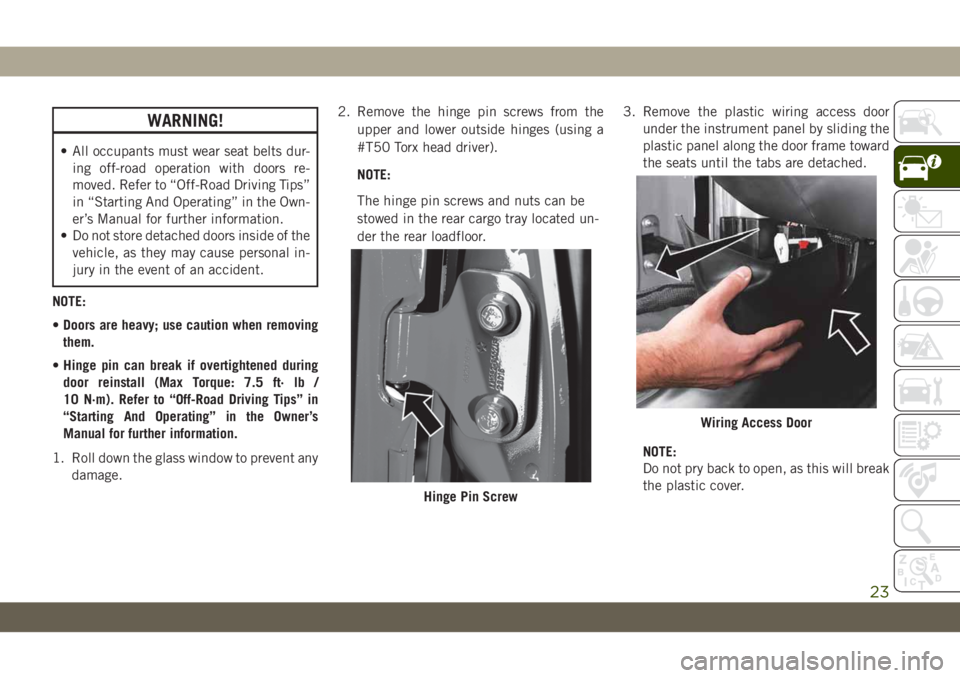
der the rear loadfloor.3. Remove the plastic wiring access door
under the instrument panel by sliding the
plastic panel along the door frame toward
the seats until the tabs are detached.
NOTE:
Do not pry back to open, as this will break
the plastic cover.
Hinge Pin Screw
Wiring Access Door
23
Page 27 of 348
WARNING!
• All occupants must wear seat belts dur-
ing off-road operation with doors re-
moved. Refer to “Off-Road Driving Tips”
in “Starting And Operating” in the Own-
er’s Manual for further information.
• Do not store detached doors inside of the
vehicle, as they may cause personal in-
jury in the event of an accident.NOTE:
•Doors are heavy; use caution when removing
them.
•Hinge pin can break if overtightened during
door reinstall (Max Torque: 7.5 ft· lb /
10 N·m). Refer to “Off-Road Driving Tips” in
“Starting And Operating” in the Owner’s
Manual for further information.
1. Roll down the glass window to prevent any
damage.
2. Remove the hinge pin screws from the
upper and lower outside hinges (using a
#T50 Torx head driver).
NOTE:
The hinge pin screws and nuts can be
stowed in the rear cargo tray located under
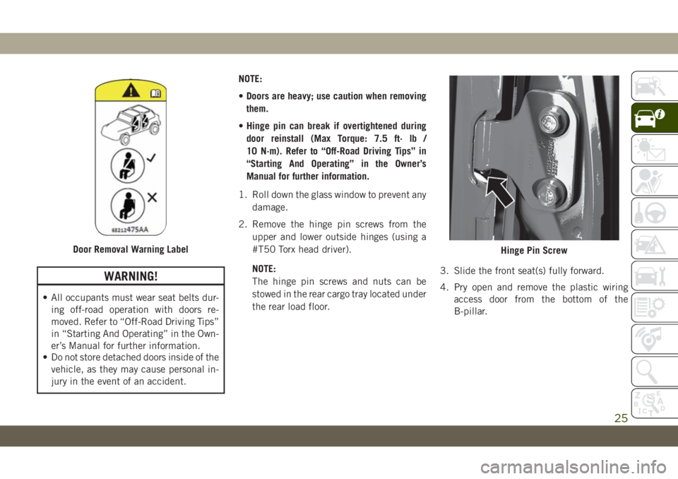
the rear load floor.3. Slide the front seat(s) fully forward.
4. Pry open and remove the plastic wiring
access door from the bottom of the
B-pillar.
Door Removal Warning LabelHinge Pin Screw
25
Page 76 of 348
Yellow Indicator Lights
/— 4WD Indicator Light — If
Equipped
This light alerts the driver that the vehicle is
in the four-wheel drive mode, and the front
and rear driveshafts are mechanically locked
together forcing the front and rear wheels to
rotate at the same speed.
4L/4WD
LOW— 4WD Low Indicator Light — If
Equipped
This light alerts the driver that the vehicle is
in the four-wheel drive LOW mode. The front
and rear driveshafts are mechanically locked
together forcing the front and rear wheels to
rotate at the same speed. Low range provides
a greater gear reduction ratio to provide in-
creased torque at the wheels.
4HPART
TIME/4WD
PART
TIME—4WD Part Time Indicator Light —
If Equipped
This light alerts the driver that the vehicle is
in the four-wheel drive part time mode, and
the front and rear driveshafts are mechani-
cally locked together forcing the front and
rear wheels to rotate at the same speed.
— Active Speed Limiter Fault Indica-
tor Light — If Equipped
This warning light will illuminate to signal
when there is a fault detected with the Active
Speed Limiter.
— Axle Locker Fault Indicator Light
This light indicates when the front and/or rear
axle locker fault has been detected.
— Front And Rear Axle Lock Indicator
Light
This light indicates when the front, rear, or
both axles have been locked. The telltale will
display the lock icon on the front and rear
axles to indicate the current lock status.
N/NEUTRAL— Neutral Indicator Light
— If Equipped
This light alerts the driver that the vehicle is
in the neutral mode.
— Rear Axle Lock Indicator Light
This light indicates when the rear axle lock
has been activated.
— Rear Fog Indicator — If Equipped
This indicator light will illuminate when the
rear fog lights are on.
— Sway Bar Indicator Light — If
Equipped
This indicator light will illuminate when the
front sway bar is disconnected.
— Wait To Start Light — If Equipped
This indicator light will illuminate for ap-
proximately two seconds when the ignition is
turned to the RUN position. Its duration may
be longer based on colder operating condi-
tions. Vehicle will not initiate start until tell-
tale is no longer displayed.
Refer to “Starting The Engine” in “Starting
And Operating” for further information.
NOTE:
The “Wait To Start” telltale may not illumi-
nate if the intake manifold temperature is
warm enough.
GETTING TO KNOW YOUR INSTRUMENT PANEL
74
Page 85 of 348
required. However, the conventional brake
system will continue to operate normally if
the “Anti-Lock Brake Warning Light” is on.
If the “Anti-Lock Brake Warning Light” is on,
the brake system should be serviced as soon
as possible to restore the benefits of anti-lock
brakes. If the “Anti-Lock Brake Warning
Light” does not come on when the ignition is
turned to the ON/RUN mode, have the light
repaired as soon as possible.
Electronic Brake Control System
Your vehicle is equipped with an advanced
Electronic Brake Control system (EBC). This
system includes Electronic Brake Force Dis-
tribution (EBD), Anti-Lock Brake System
(ABS), Brake Assist System (BAS), Hill Start
Assist (HSA), Traction Control System (TCS),
Electronic Stability Control (ESC), and Elec-
tronic Roll Mitigation (ERM). These systems
work together to enhance both vehicle stabil-
ity and control in various driving conditions.Your vehicle may also be equipped with
Trailer Sway Control (TSC), Ready Alert Brak-
ing (RAB), Rain Brake Support (RBS), Dy-
namic Steering Torque (DST), and Hill De-
scent Control (HDC).
Electronic Brake Force Distribution (EBD)
This function manages the distribution of the
braking torque between the front and rear
axles by limiting braking pressure to the rear
axle. This is done to prevent overslip of the
rear wheels to avoid vehicle instability, and to
prevent the rear axle from entering ABS be-
fore the front axle.
Brake System Warning Light
The red “Brake System Warning Light” will
turn on when the ignition is turned to the
ON/RUN mode and may stay on for as long as
four seconds.
If the “Brake System Warning Light” remains
on or comes on while driving, it indicates that
the brake system is not functioning properly
and that immediate service is required. If the“Brake System Warning Light” does not
come on when the ignition is turned to the
ON/RUN mode, have the light repaired as
soon as possible.
Brake Assist System (BAS)
The BAS is designed to optimize the vehicle’s
braking capability during emergency braking
maneuvers. The system detects an emer-
gency braking situation by sensing the rate
and amount of brake application and then
applies optimum pressure to the brakes. This
can help reduce braking distances. The BAS
complements the anti-lock brake system
(ABS). Applying the brakes very quickly re-
sults in the best BAS assistance. To receive
the benefit of the system, you must apply
continuous braking pressure during the stop-
ping sequence, (do not “pump” the brakes).
Do not reduce brake pedal pressure unless
braking is no longer desired. Once the brake
pedal is released, the BAS is deactivated.
WARNING!
The Brake Assist System (BAS) cannot
prevent the natural laws of physics from
83
Page 87 of 348
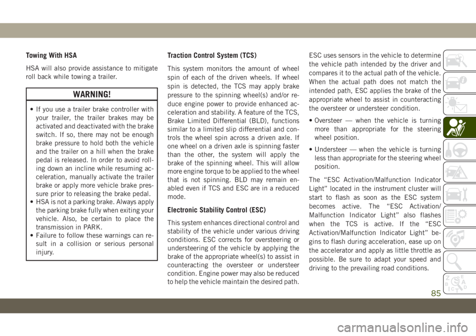
Towing With HSA
HSA will also provide assistance to mitigate
roll back while towing a trailer.
WARNING!
• If you use a trailer brake controller with
your trailer, the trailer brakes may be
activated and deactivated with the brake
switch. If so, there may not be enough
brake pressure to hold both the vehicle
and the trailer on a hill when the brake
pedal is released. In order to avoid roll-
ing down an incline while resuming ac-
celeration, manually activate the trailer
brake or apply more vehicle brake pres-
sure prior to releasing the brake pedal.
• HSA is not a parking brake. Always apply
the parking brake fully when exiting your
vehicle. Also, be certain to place the
transmission in PARK.
• Failure to follow these warnings can re-
sult in a collision or serious personal
injury.
Traction Control System (TCS)
This system monitors the amount of wheel
spin of each of the driven wheels. If wheel
spin is detected, the TCS may apply brake
pressure to the spinning wheel(s) and/or re-
duce engine power to provide enhanced ac-
celeration and stability. A feature of the TCS,
Brake Limited Differential (BLD), functions
similar to a limited slip differential and con-
trols the wheel spin across a driven axle. If
one wheel on a driven axle is spinning faster
than the other, the system will apply the
brake of the spinning wheel. This will allow
more engine torque to be applied to the wheel
that is not spinning. BLD may remain en-
abled even if TCS and ESC are in a reduced
mode.
Electronic Stability Control (ESC)
This system enhances directional control and
stability of the vehicle under various driving
conditions. ESC corrects for oversteering or
understeering of the vehicle by applying the
brake of the appropriate wheel(s) to assist in
counteracting the oversteer or understeer
condition. Engine power may also be reduced
to help the vehicle maintain the desired path.ESC uses sensors in the vehicle to determine
the vehicle path intended by the driver and
compares it to the actual path of the vehicle.
When the actual path does not match the
intended path, ESC applies the brake of the
appropriate wheel to assist in counteracting
the oversteer or understeer condition.
• Oversteer — when the vehicle is turning
more than appropriate for the steering
wheel position.
• Understeer — when the vehicle is turning
less than appropriate for the steering wheel
position.
The “ESC Activation/Malfunction Indicator
Light” located in the instrument cluster will
start to flash as soon as the ESC system
becomes active. The “ESC Activation/
Malfunction Indicator Light” also flashes
when the TCS is active. If the “ESC
Activation/Malfunction Indicator Light” be-
gins to flash during acceleration, ease up on
the accelerator and apply as little throttle as
possible. Be sure to adapt your speed and
driving to the prevailing road conditions.
85
Page 89 of 348
WARNING!
• When in “Partial Off” mode, the TCS
functionality of ESC, (except for the lim-
ited slip feature described in the TCS
section), has been disabled and the
“ESC Off Indicator Light” will be illumi-
nated. When in “Partial Off” mode, the
engine power reduction feature of TCS is
disabled, and the enhanced vehicle sta-
bility offered by the ESC system is re-
duced.
• Trailer Sway control (TSC) is disabled
when the ESC system is in the “Partial
Off” mode.
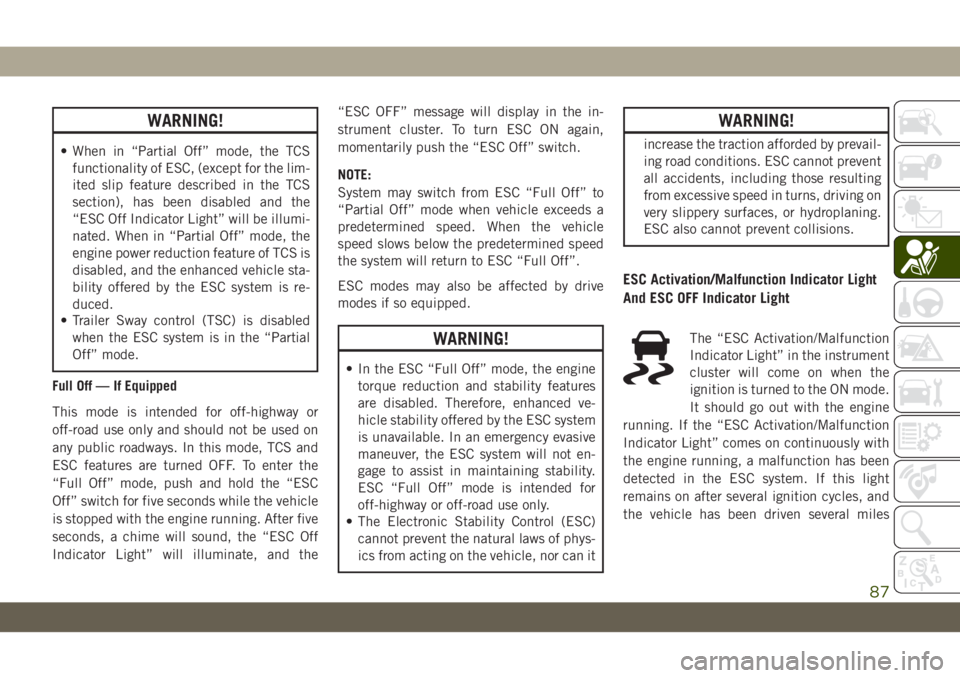
Full Off — If Equipped
This mode is intended for off-highway or
off-road use only and should not be used on
any public roadways. In this mode, TCS and
ESC features are turned OFF. To enter the
“Full Off” mode, push and hold the “ESC
Off” switch for five seconds while the vehicle
is stopped with the engine running. After five
seconds, a chime will sound, the “ESC Off
Indicator Light” will illuminate, and the“ESC OFF” message will display in the in-
strument cluster. To turn ESC ON again,
momentarily push the “ESC Off” switch.
NOTE:
System may switch from ESC “Full Off” to
“Partial Off” mode when vehicle exceeds a
predetermined speed. When the vehicle
speed slows below the predetermined speed
the system will return to ESC “Full Off”.
ESC modes may also be affected by drive
modes if so equipped.
WARNING!
• In the ESC “Full Off” mode, the engine
torque reduction and stability features
are disabled. Therefore, enhanced ve-
hicle stability offered by the ESC system
is unavailable. In an emergency evasive
maneuver, the ESC system will not en-
gage to assist in maintaining stability.
ESC “Full Off” mode is intended for
off-highway or off-road use only.
• The Electronic Stability Control (ESC)
cannot prevent the natural laws of phys-
ics from acting on the vehicle, nor can it
WARNING!
increase the traction afforded by prevail-
ing road conditions. ESC cannot prevent
all accidents, including those resulting
from excessive speed in turns, driving on
very slippery surfaces, or hydroplaning.
ESC also cannot prevent collisions.
ESC Activation/Malfunction Indicator Light
And ESC OFF Indicator Light
The “ESC Activation/Malfunction
Indicator Light” in the instrument
cluster will come on when the
ignition is turned to the ON mode.
It should go out with the engine
running. If the “ESC Activation/Malfunction
Indicator Light” comes on continuously with
the engine running, a malfunction has been
detected in the ESC system. If this light
remains on after several ignition cycles, and
the vehicle has been driven several miles
87
Page 153 of 348
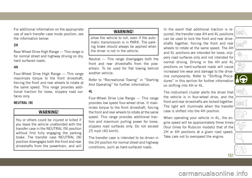
For additional information on the appropriate
use of each transfer case mode position, see
the information below:
2H
Rear Wheel Drive High Range — This range is
for normal street and highway driving on dry,
hard surfaced roads.
4H
Four-Wheel Drive High Range — This range
maximizes torque to the front driveshaft,
forcing the front and rear wheels to rotate at
the same speed. This range provides addi-
tional traction for loose, slippery road sur-
faces only.
NEUTRAL (N)
WARNING!
You or others could be injured or killed if
you leave the vehicle unattended with the
transfer case in the NEUTRAL (N) position
without first fully engaging the parking
brake. The transfer case NEUTRAL (N)
position disengages both the front and rear
driveshafts from the powertrain, and will
WARNING!
allow the vehicle to roll, even if the auto-
matic transmission is in PARK. The park-
ing brake should always be applied when
the driver is not in the vehicle.
Neutral — This range disengages both the
front and rear driveshafts from the pow-
ertrain. To be used for flat towing behind
another vehicle.
Refer to “Recreational Towing” in “Starting
And Operating” for further information.
4L
Four-Wheel Drive Low Range — This range
provides low speed four-wheel drive. It maxi-
mizes torque to the front driveshaft, forcing
the front and rear wheels to rotate at the same
speed. This range provides additional trac-
tion and maximum pulling power for loose,
slippery road surfaces only. Do not exceed
25 mph (40 km/h).
The transfer case is intended to be driven in
the 2H position for normal street and highway
conditions, such as hard-surfaced roads.In the event that additional traction is re-
quired, the transfer case 4H and 4L positions
can be used to lock the front and rear drive-
shafts together, forcing the front and rear
wheels to rotate at the same speed. The 4H
and 4L positions are intended for loose, slip-
pery road surfaces only and not intended for
normal driving. Driving in the 4H and 4L
positions on hard-surfaced roads will cause
increased tire wear and damage to the drive-
line components. Refer to “Shifting Proce-
dures” in this section for further information
on shifting into 4H or 4L.
The instrument cluster alerts the driver that
the vehicle is in four-wheel drive, and the
front and rear driveshafts are locked together.
The light will illuminate when the transfer
case is shifted into the 4H position.
When operating your vehicle in 4L, the en-
gine speed will be approximately three times
(four times for Rubicon models) that of the
2H or 4H positions at a given road speed.
Take care not to overspeed the engine.
151
Page 155 of 348
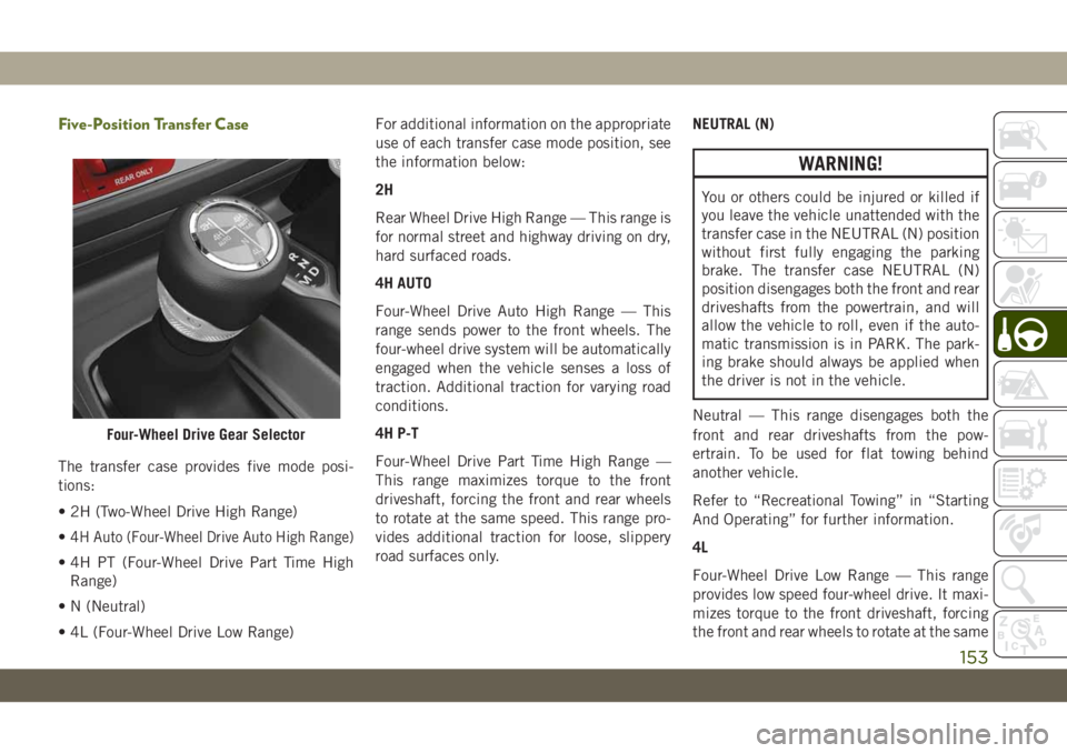
Five-Position Transfer Case
The transfer case provides five mode posi-
tions:
• 2H (Two-Wheel Drive High Range)
•
4H Auto (Four-Wheel Drive Auto High Range)
• 4H PT (Four-Wheel Drive Part Time High
Range)
• N (Neutral)
• 4L (Four-Wheel Drive Low Range)For additional information on the appropriate
use of each transfer case mode position, see
the information below:
2H
Rear Wheel Drive High Range — This range is
for normal street and highway driving on dry,
hard surfaced roads.
4H AUTO
Four-Wheel Drive Auto High Range — This
range sends power to the front wheels. The
four-wheel drive system will be automatically
engaged when the vehicle senses a loss of
traction. Additional traction for varying road
conditions.
4H P-T
Four-Wheel Drive Part Time High Range —
This range maximizes torque to the front
driveshaft, forcing the front and rear wheels
to rotate at the same speed. This range pro-
vides additional traction for loose, slippery
road surfaces only.NEUTRAL (N)
WARNING!
You or others could be injured or killed if
you leave the vehicle unattended with the
transfer case in the NEUTRAL (N) position
without first fully engaging the parking
brake. The transfer case NEUTRAL (N)
position disengages both the front and rear
driveshafts from the powertrain, and will
allow the vehicle to roll, even if the auto-
matic transmission is in PARK. The park-
ing brake should always be applied when
the driver is not in the vehicle.
Neutral — This range disengages both the
front and rear driveshafts from the pow-
ertrain. To be used for flat towing behind
another vehicle.
Refer to “Recreational Towing” in “Starting
And Operating” for further information.
4L
Four-Wheel Drive Low Range — This range
provides low speed four-wheel drive. It maxi-
mizes torque to the front driveshaft, forcing
the front and rear wheels to rotate at the same
Four-Wheel Drive Gear Selector
153
Page 157 of 348
NOTE:
• Do not attempt to make a shift while only
the front or rear wheels are spinning. The
front and rear driveshaft speeds must be
equal for the shift to take place. Shifting
while only the front or rear wheels are
spinning can cause damage to the transfer
case.
• Delayed shifts out of four-wheel drive may
be experienced due to uneven tire wear, low
or uneven tire pressures, excessive vehicle
loading, or cold temperatures.
• Shifting effort will increase with speed, this
is normal.
During cold weather, you may experience
increased effort in shifting until the transfer
case fluid warms up. This is normal.
4H Part Time/4H Auto To 4L Or 4L To 4H Part
Time/4H Auto
With the vehicle rolling at 2 to 3 mph (3 to
5 km/h), shift the transmission into NEU-
TRAL (N). While the vehicle is coasting at
2 to 3 mph (3 to 5 km/h), shift the transfer
case lever firmly to the desired position. Donot pause with the transfer case in N (Neu-
tral). Once the shift is completed, place the
transmission into DRIVE.
NOTE:
Shifting into or out of 4L is possible with the
vehicle completely stopped; however, diffi-
culty may occur due to the mating teeth not
being properly aligned. Several attempts may
be required for clutch teeth alignment and
shift completion to occur. The preferred
method is with the vehicle rolling at 2 to
3 mph (3 to 5 km/h). Avoid attempting to
engage or disengage 4L with the vehicle mov-
ing faster than 2 to 3 mph (3 to 5 km/h).
WARNING!
Failure to engage a transfer case position
completely can cause transfer case dam-
age or loss of power and vehicle control.
You could have a collision. Do not drive the
vehicle unless the transfer case is fully
engaged.
Trac-Lok Rear Axle — If Equipped
The Trac-Lok rear axle provides a constant
driving force to both rear wheels and reduces
wheel spin caused by the loss of traction at
one driving wheel. If traction differs between
the two rear wheels, the differential auto-
matically proportions the usable torque by
providing more torque to the wheel that has
traction.
Trac-Lok is especially helpful during slippery
driving conditions. With both rear wheels on a
slippery surface, a slight application of the
accelerator will supply maximum traction.
WARNING!
On vehicles equipped with a limited-slip
differential, never run the engine with one
rear wheel off the ground. The vehicle may
drive through the rear wheel remaining on
the ground and cause you to lose control of
your vehicle.
155
Page 159 of 348
Push the SWAY BAR switch to activate the
system. Push the switch again to deactivate
the system. The “Sway Bar Indicator Light”
(located in the instrument cluster) will illumi-
nate when the bar is disconnected. The
“Sway Bar Indicator Light” will flash during
activation transition, or when activation con-
ditions are not met. The stabilizer/sway bar
should remain in on-road mode during nor-
mal driving conditions.
WARNING!
Ensure the stabilizer/sway bar is recon-
nected before driving on hard surfaced
roads or at speeds above 18 mph
(29 km/h); a disconnected stabilizer/sway
bar may contribute to the loss of vehicle
control, which could result in serious in-
jury. Under certain circumstances, the
front stabilizer/sway bar enhances vehicle
stability and assists with vehicle control.
The system monitors vehicle speed and
will attempt to reconnect the stabilizer/
sway bar at speeds over 18 mph
(29 km/h). This is indicated by a flashing
or solid “Sway Bar Indicator Light.” Once
WARNING!
vehicle speed is reduced below 14 mph
(22 km/h), the system will once again
attempt to return to off-road mode.
To disconnect the stabilizer/sway bar, shift to
either 4H or 4L and push the SWAY BAR
switch to obtain the off-road position. Refer
to “Four-Wheel Drive Operation” in this sec-
tion for further information. The “Sway Bar
Indicator Light” will flash until the stabilizer/
sway bar has been fully disconnected.
NOTE:
The stabilizer/sway bar may be torque locked
due to left and right suspension height differ-
ences. This condition is due to driving sur-
face differences or vehicle loading. In order
for the stabilizer/sway bar to disconnect/
reconnect, the right and left halves of the bar
must be aligned. This alignment may require
that the vehicle be driven onto level ground or
rocked from side to side.
To return to on-road mode, push the SWAY
BAR switch again.
WARNING!
If the stabilizer/sway bar will not return to
on-road mode, the “Sway Bar Indicator
Light” will flash in the instrument cluster
and vehicle stability may be reduced. Do
not attempt to drive the vehicle over
18 mph (29 km/h). Driving faster than
18 mph (29 km/h) with a disconnected
stabilizer/sway bar may contribute to the
loss of vehicle control, which could result
in serious injury.
STOP/START SYSTEM —
AUTOMATIC
TRANSMISSION (IF
EQUIPPED)
The Stop/Start function is developed to re-
duce fuel consumption. The system will stop
the engine automatically during a vehicle
stop if the required conditions are met. Re-
leasing the brake pedal or pressing the accel-
erator pedal will automatically re-start the
engine.
157