tow JEEP XJ 1995 Service And Repair Manual
[x] Cancel search | Manufacturer: JEEP, Model Year: 1995, Model line: XJ, Model: JEEP XJ 1995Pages: 2158, PDF Size: 81.9 MB
Page 1557 of 2158
(36) If equipped, install the cruise control wire har-
ness. Install the turn signal stalk by pushing it
straight into the column.
(37) Insert the hazard warning knob in the hazard
warning switch and press it inward. Align and install
the turn signal switch retaining screws. Ensure that
the turn signal switch is properly seated before tight-
ening the screws. Tighten the screws to 4 Nzm (33 in.
lbs.) torque. Thread the hazard warning switch knob
into the switch and pull the knob outward.
(38) Install and seat the upper bearing race in the
key/lock cylinder housing.
(39) Install the upper bearing preload spring, the
canceling cam and the lockplate.
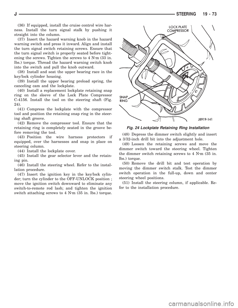
(40) Install a replacement lockplate retaining snap
ring on the sleeve of the Lock Plate Compressor
C-4156. Install the tool on the steering shaft (Fig.
24).
(41) Compress the lockplate with the compressor
tool and position the retaining snap ring in the steer-
ing shaft groove.
(42) Remove the compressor tool. Ensure that the
retaining ring is completely seated in the groove be-
fore removing the tool.
(43) Position the wire harness protectors if
equipped, over the harnesses and snap in place on
steering column.
(44) Install the lockplate cover.
(45) Install the gear selector lever and the retain-
ing pin.
(46) Install the steering wheel. Refer to the instal-
lation procedure.
(47) Insert the ignition key in the key/lock cylin-
der; turn the cylinder to the OFF-UNLOCK position ;
move the ignition switch downward to eliminate any
switch-to-remote rod lash; and tighten the ignition
switch attaching screws to 4 Nzm (35 in. lbs.) torque.(48) Depress the dimmer switch slightly and insert
a 3/32-inch drill bit into the adjustment hole.
(49) Loosen the retaining screws and move the
dimmer switch toward the steering wheel. Tighten
the dimmer switch retaining screws to 4 Nzm (35 in.
lbs.) torque.
(50) Remove the drill bit and test operation by
moving the dimmer switch stalk. Test the dimmer
switch operation in the full-up, down and center
steering wheel positions.
(51) Install the steering column, if applicable. Re-
fer to the installation procedure.
Fig. 24 Lockplate Retaining Ring Installation
JSTEERING 19 - 73
Page 1563 of 2158
TRANSMISSION AND TRANSFER CASE
CONTENTS
page page
30RH/32RH AUTOMATIC TRANSMISSION.... 67
AW 4 AUTOMATIC TRANSMISSION........ 165
AX 15 MANUAL TRANSMISSION........... 33
AX 4/5 MANUAL TRANSMISSION............ 1NP231 TRANSFER CASE................. 283
NP242 TRANSFER CASE................. 306
TRANSMISSION/TRANSFER CASE
SPECIFICATIONS..................... 333
AX 4/5 MANUAL TRANSMISSION
INDEX
page page
Cleaning and Inspection.................... 13
Gear Ratios.............................. 2
General Information........................ 1
Recommended Lubricant.................... 2
Service Diagnosis.......................... 2
Shift Pattern.............................. 2Transmission Assembly and Adjustment......... 16
Transmission Disassembly and Overhaul......... 5
Transmission Identification................... 2
Transmission Installation..................... 5
Transmission Removal...................... 3
GENERAL INFORMATION
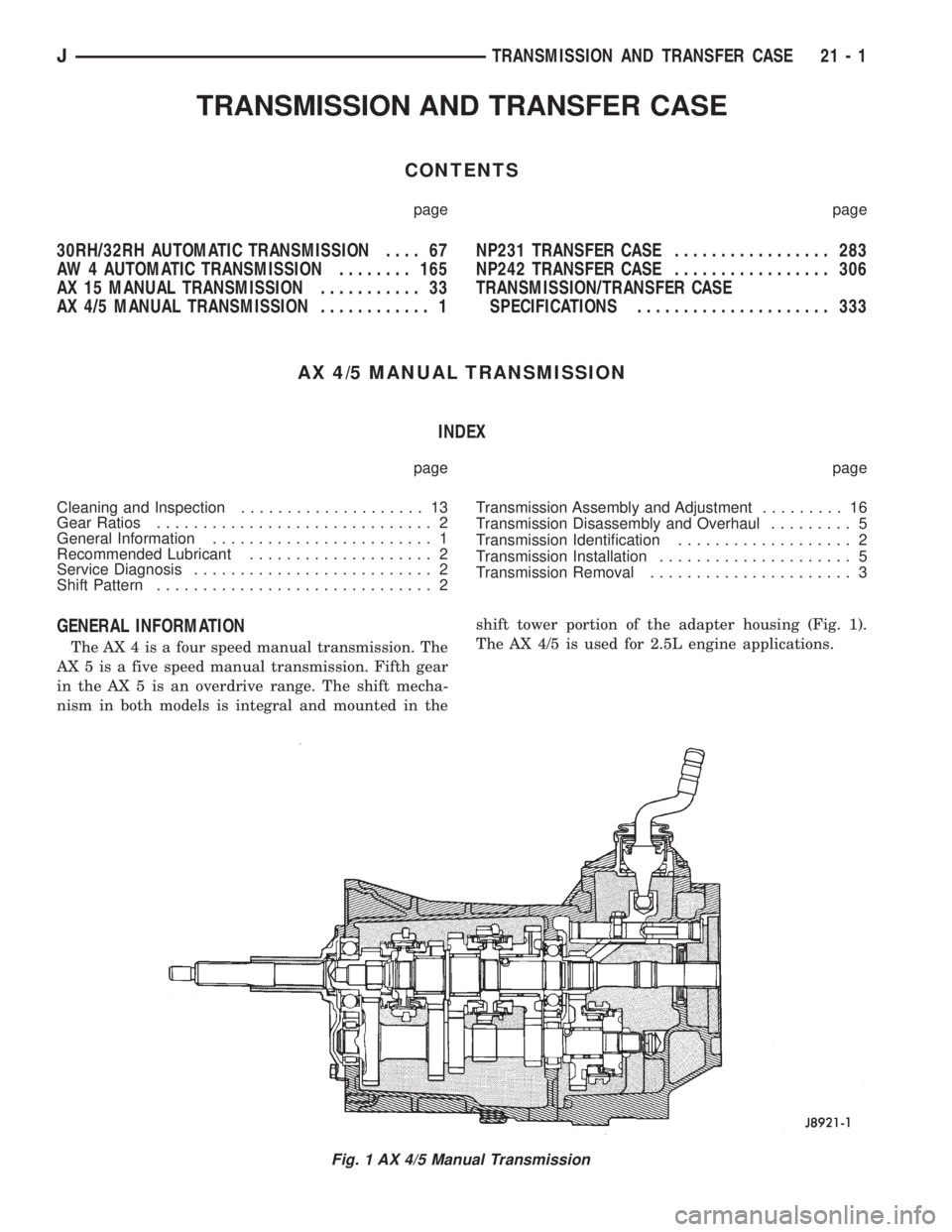
The AX 4 is a four speed manual transmission. The
AX 5 is a five speed manual transmission. Fifth gear
in the AX 5 is an overdrive range. The shift mecha-
nism in both models is integral and mounted in theshift tower portion of the adapter housing (Fig. 1).
The AX 4/5 is used for 2.5L engine applications.
Fig. 1 AX 4/5 Manual Transmission
JTRANSMISSION AND TRANSFER CASE 21 - 1
Page 1566 of 2158
(7) Disconnect transfer case shift linkage at trans-
fer case.
(8) Disconnect vehicle speed sensor wires and
transfer case vent hose.
(9) Remove slave cylinder from clutch housing.
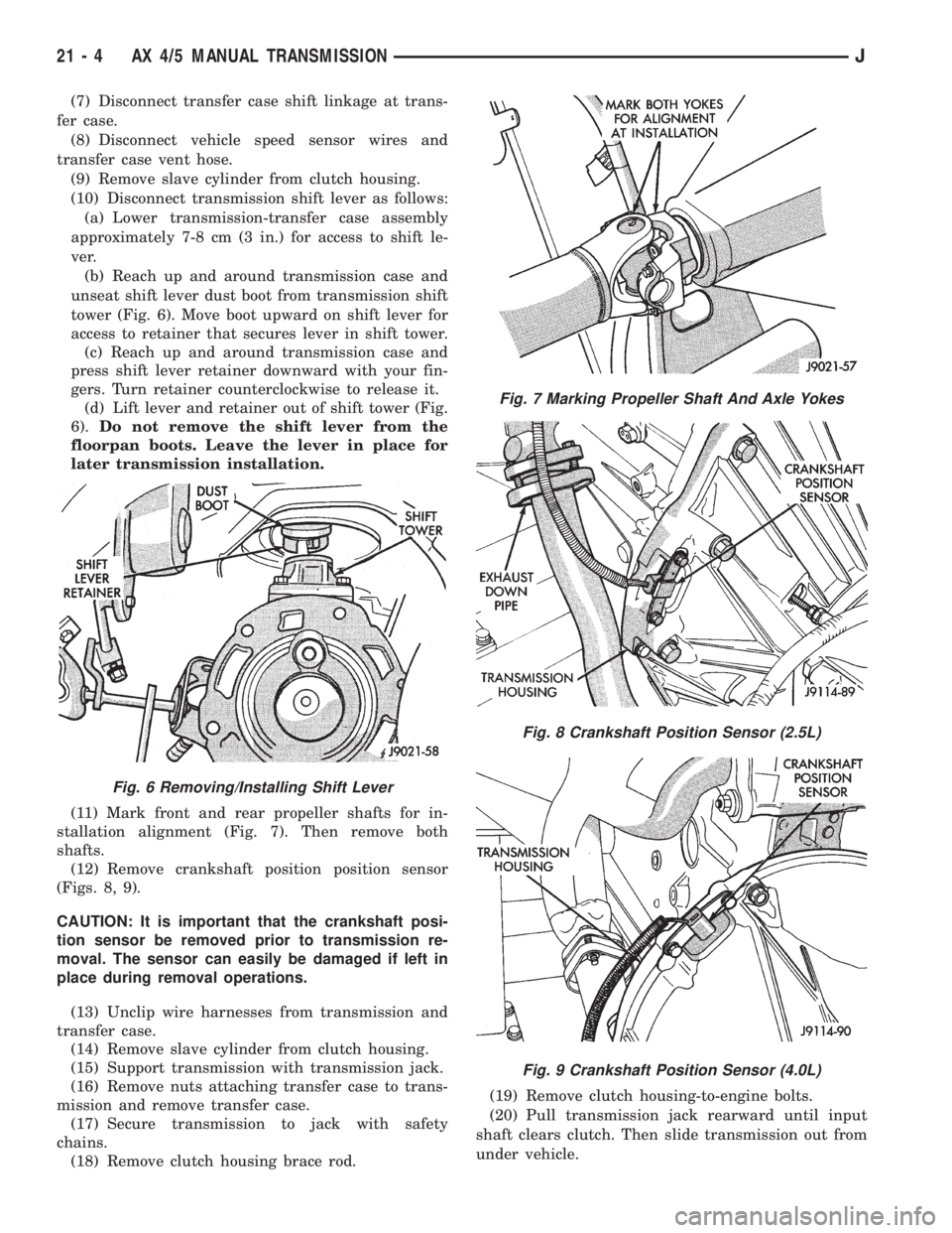
(10) Disconnect transmission shift lever as follows:
(a) Lower transmission-transfer case assembly
approximately 7-8 cm (3 in.) for access to shift le-
ver.
(b) Reach up and around transmission case and
unseat shift lever dust boot from transmission shift
tower (Fig. 6). Move boot upward on shift lever for
access to retainer that secures lever in shift tower.
(c) Reach up and around transmission case and
press shift lever retainer downward with your fin-
gers. Turn retainer counterclockwise to release it.
(d) Lift lever and retainer out of shift tower (Fig.
6).Do not remove the shift lever from the
floorpan boots. Leave the lever in place for
later transmission installation.
(11) Mark front and rear propeller shafts for in-
stallation alignment (Fig. 7). Then remove both
shafts.
(12) Remove crankshaft position position sensor
(Figs. 8, 9).
CAUTION: It is important that the crankshaft posi-
tion sensor be removed prior to transmission re-
moval. The sensor can easily be damaged if left in
place during removal operations.
(13) Unclip wire harnesses from transmission and
transfer case.
(14) Remove slave cylinder from clutch housing.
(15) Support transmission with transmission jack.
(16) Remove nuts attaching transfer case to trans-
mission and remove transfer case.
(17) Secure transmission to jack with safety
chains.
(18) Remove clutch housing brace rod.(19) Remove clutch housing-to-engine bolts.
(20) Pull transmission jack rearward until input
shaft clears clutch. Then slide transmission out from
under vehicle.
Fig. 6 Removing/Installing Shift Lever
Fig. 7 Marking Propeller Shaft And Axle Yokes
Fig. 8 Crankshaft Position Sensor (2.5L)
Fig. 9 Crankshaft Position Sensor (4.0L)
21 - 4 AX 4/5 MANUAL TRANSMISSIONJ
Page 1567 of 2158
(21) Remove clutch release bearing, release fork
and retainer clip.
(22) Remove clutch housing from transmission.
TRANSMISSION INSTALLATION
(1) Install clutch housing on transmission. Tighten
housing bolts to 37 Nzm (27 ft. lbs.) torque.
(2) Lubricate contact surfaces of release fork pivot
ball stud and release fork with high temp grease.
Then install release bearing, fork and retainer clip.
(3) Mount transmission on transmission jack.
(4) Lightly lubricate pilot bearing and transmis-
sion input shaft splines with Mopar high temp
grease.
(5) Align transmission input shaft, release bearing,
and clutch disc splines. Then slide transmission into
place.
(6) Install and tighten clutch housing-to-engine
bolts to 38 Nzm (28 ft. lbs.) torque.Be sure the
housing is properly seated on engine block be-
fore tightening bolts.
(7) Lower transmission approximately 7-8 cm (3
in.) for access to shift tower. Be sure transmission is
in first or third gear.
(8) Reach up and around transmission and insert
shift lever in shift tower. Press lever retainer down-
ward and turn it clockwise to lock it in place. Then
install lever dust boot on shift tower.
(9) Install slave cylinder in clutch housing.
(10) Align and install transfer case on and trans-
mission. Tighten transfer case-to-transmission nuts
to 35 Nzm (26 ft. lbs.) torque.
(11) Connect transfer case vent hose and shift link-
age. Check and adjust linkage if necessary.
(12) Connect transfer case vent hose.
(13) Secure wire harnesses in clips/tie straps on
transmission and transfer case.
(14) Connect backup light switch wires.
(15) Connect vehicle speed sensor wires.
(16) Install and connect crankshaft position sensor.
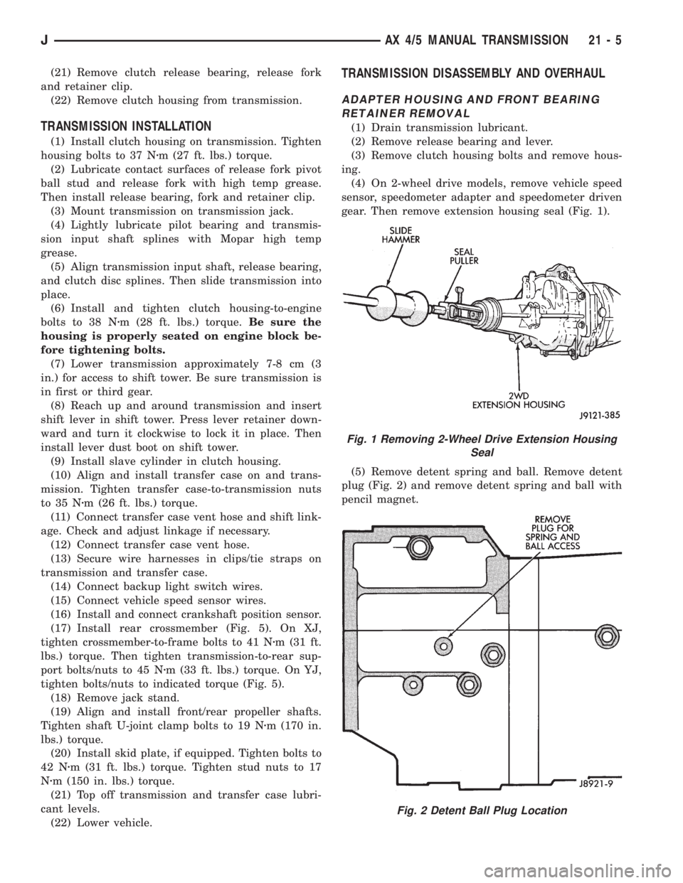
(17) Install rear crossmember (Fig. 5). On XJ,
tighten crossmember-to-frame bolts to 41 Nzm (31 ft.
lbs.) torque. Then tighten transmission-to-rear sup-
port bolts/nuts to 45 Nzm (33 ft. lbs.) torque. On YJ,
tighten bolts/nuts to indicated torque (Fig. 5).
(18) Remove jack stand.
(19) Align and install front/rear propeller shafts.
Tighten shaft U-joint clamp bolts to 19 Nzm (170 in.
lbs.) torque.
(20) Install skid plate, if equipped. Tighten bolts to
42 Nzm (31 ft. lbs.) torque. Tighten stud nuts to 17
Nzm (150 in. lbs.) torque.
(21) Top off transmission and transfer case lubri-
cant levels.
(22) Lower vehicle.
TRANSMISSION DISASSEMBLY AND OVERHAUL
ADAPTER HOUSING AND FRONT BEARING
RETAINER REMOVAL
(1) Drain transmission lubricant.
(2) Remove release bearing and lever.
(3) Remove clutch housing bolts and remove hous-
ing.
(4) On 2-wheel drive models, remove vehicle speed
sensor, speedometer adapter and speedometer driven
gear. Then remove extension housing seal (Fig. 1).
(5) Remove detent spring and ball. Remove detent
plug (Fig. 2) and remove detent spring and ball with
pencil magnet.
Fig. 1 Removing 2-Wheel Drive Extension Housing
Seal
Fig. 2 Detent Ball Plug Location
JAX 4/5 MANUAL TRANSMISSION 21 - 5
Page 1575 of 2158
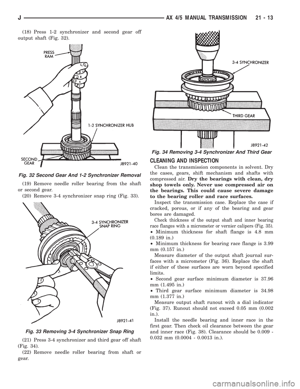
(18) Press 1-2 synchronizer and second gear off
output shaft (Fig. 32).
(19) Remove needle roller bearing from the shaft
or second gear.
(20) Remove 3-4 synchronizer snap ring (Fig. 33).
(21) Press 3-4 synchronizer and third gear off shaft
(Fig. 34).
(22) Remove needle roller bearing from shaft or
gear.
CLEANING AND INSPECTION
Clean the transmission components in solvent. Dry
the cases, gears, shift mechanism and shafts with
compressed air.Dry the bearings with clean, dry
shop towels only. Never use compressed air on
the bearings. This could cause severe damage
to the bearing roller and race surfaces.
Inspect the transmission case. Replace the case if
cracked, porous, or if any of the bearing and gear
bores are damaged.
Check thickness of the output shaft and inner bearing
race flanges with a micrometer or vernier calipers (Fig. 35).
²Minimum thickness for shaft flange is 4.8 mm
(0.189 in.)
²Minimum thickness for bearing race flange is 3.99
mm (0.157 in.)
Measure diameter of the output shaft journal sur-
faces with a micrometer (Fig. 36). Replace the shaft
if either of these surfaces are worn beyond specified
limits.
²Second gear surface minimum diameter is 37.96
mm (1.495 in.)
²Third gear surface minimum diameter is 34.98
mm (1.377 in.)
Measure output shaft runout with a dial indicator
(Fig. 37). Runout should not exceed 0.05 mm (0.002
in.).
Install the needle bearing and inner race in the
first gear. Then check oil clearance between the gear
and inner race (Fig. 38). Clearance should be 0.009 -
0.032 mm (0.0004 - 0.0013 in.).
Fig. 32 Second Gear And 1-2 Synchronizer Removal
Fig. 33 Removing 3-4 Synchronizer Snap Ring
Fig. 34 Removing 3-4 Synchronizer And Third Gear
JAX 4/5 MANUAL TRANSMISSION 21 - 13
Page 1581 of 2158
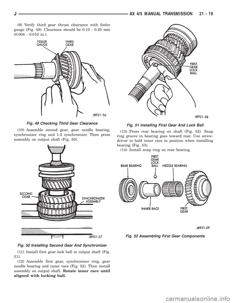
(9) Verify third gear thrust clearance with feeler
gauge (Fig. 49). Clearance should be 0.10 - 0.25 mm
(0.004 - 0.010 in.).
(10) Assemble second gear, gear needle bearing,
synchronizer ring and 1-2 synchronizer. Then press
assembly on output shaft (Fig. 50).
(11) Install first gear lock ball in output shaft (Fig.
51).
(12) Assemble first gear, synchronizer ring, gear
needle bearing and inner race (Fig. 52). Then install
assembly on output shaft.Rotate inner race until
aligned with locking ball.(13) Press rear bearing on shaft (Fig. 52). Snap
ring groove in bearing goes toward rear. Use screw-
driver to hold inner race in position when installing
bearing (Fig. 53).
(14) Install snap ring on rear bearing.
Fig. 49 Checking Third Gear Clearance
Fig. 50 Installing Second Gear And Synchronizer
Fig. 51 Installing First Gear And Lock Ball
Fig. 52 Assembling First Gear Components
JAX 4/5 MANUAL TRANSMISSION 21 - 19
Page 1594 of 2158
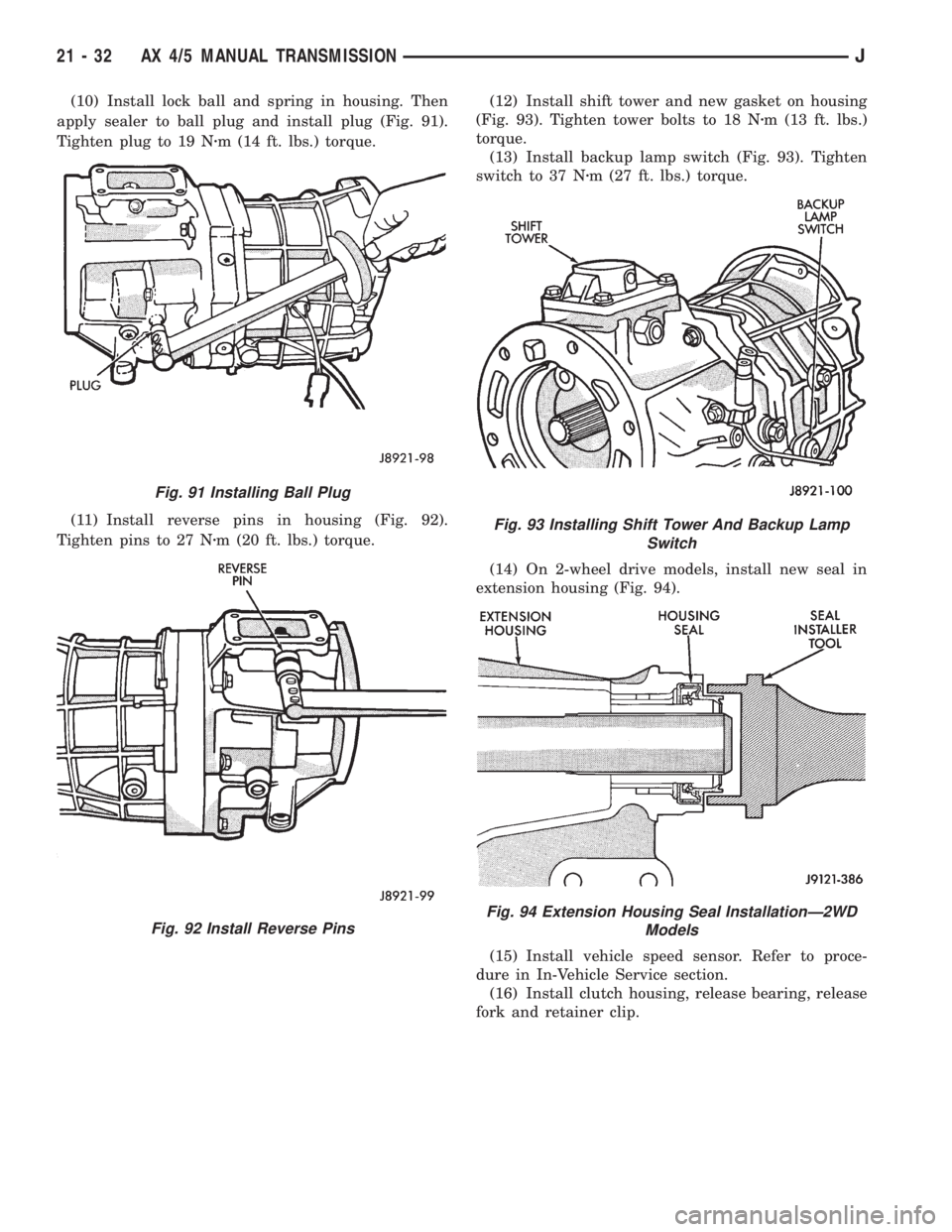
(10) Install lock ball and spring in housing. Then
apply sealer to ball plug and install plug (Fig. 91).
Tighten plug to 19 Nzm (14 ft. lbs.) torque.
(11) Install reverse pins in housing (Fig. 92).
Tighten pins to 27 Nzm (20 ft. lbs.) torque.(12) Install shift tower and new gasket on housing
(Fig. 93). Tighten tower bolts to 18 Nzm (13 ft. lbs.)
torque.
(13) Install backup lamp switch (Fig. 93). Tighten
switch to 37 Nzm (27 ft. lbs.) torque.
(14) On 2-wheel drive models, install new seal in
extension housing (Fig. 94).
(15) Install vehicle speed sensor. Refer to proce-
dure in In-Vehicle Service section.
(16) Install clutch housing, release bearing, release
fork and retainer clip.
Fig. 91 Installing Ball Plug
Fig. 92 Install Reverse Pins
Fig. 93 Installing Shift Tower And Backup Lamp
Switch
Fig. 94 Extension Housing Seal InstallationÐ2WD
Models
21 - 32 AX 4/5 MANUAL TRANSMISSIONJ
Page 1595 of 2158
AX 15 MANUAL TRANSMISSION
INDEX
page page
General Information....................... 33
Service Diagnosis......................... 34
Transmission Assembly and Adjustment......... 52
Transmission Disassembly and Overhaul........ 37
Transmission Gear Ratios................... 34
Transmission Identification.................. 33Transmission Installation.................... 36
Transmission Lubricant..................... 34
Transmission Removal..................... 35
Transmission Shift Pattern................... 34
Transmission Switch and Plug Locations........ 34
GENERAL INFORMATION
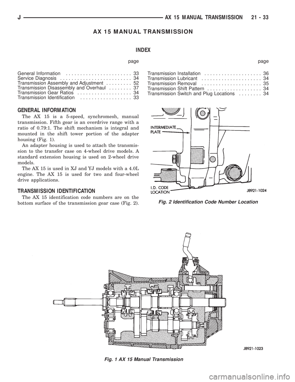
The AX 15 is a 5-speed, synchromesh, manual
transmission. Fifth gear is an overdrive range with a
ratio of 0.79:1. The shift mechanism is integral and
mounted in the shift tower portion of the adapter
housing (Fig. 1).
An adapter housing is used to attach the transmis-
sion to the transfer case on 4-wheel drive models. A
standard extension housing is used on 2-wheel drive
models.
The AX 15 is used in XJ and YJ models with a 4.0L
engine. The AX 15 is used for two and four-wheel
drive applications.
TRANSMISSION IDENTIFICATION
The AX 15 identification code numbers are on the
bottom surface of the transmission gear case (Fig. 2).
Fig. 1 AX 15 Manual Transmission
Fig. 2 Identification Code Number Location
JAX 15 MANUAL TRANSMISSION 21 - 33
Page 1598 of 2158
(6) On XJ, remove rear crossmember. On YJ, re-
move skid plate (Fig. 1).
(7) Disconnect transmission shift linkage, speed-
ometer cable, transfer case vacuum lines and clutch
hydraulic lines.
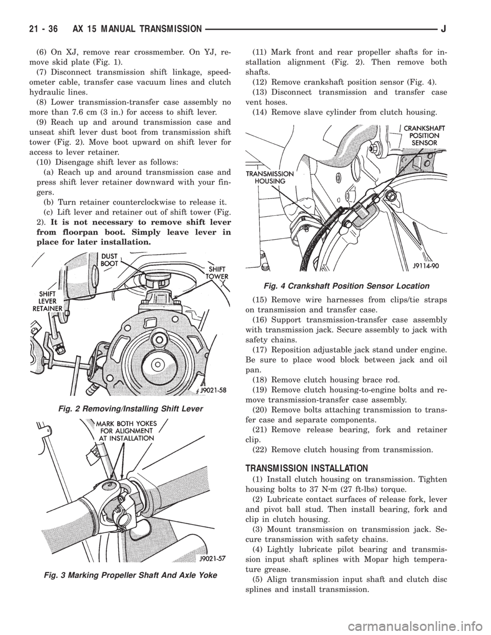
(8) Lower transmission-transfer case assembly no
more than 7.6 cm (3 in.) for access to shift lever.
(9) Reach up and around transmission case and
unseat shift lever dust boot from transmission shift
tower (Fig. 2). Move boot upward on shift lever for
access to lever retainer.
(10) Disengage shift lever as follows:
(a) Reach up and around transmission case and
press shift lever retainer downward with your fin-
gers.
(b) Turn retainer counterclockwise to release it.
(c) Lift lever and retainer out of shift tower (Fig.
2).It is not necessary to remove shift lever
from floorpan boot. Simply leave lever in
place for later installation.(11) Mark front and rear propeller shafts for in-
stallation alignment (Fig. 2). Then remove both
shafts.
(12) Remove crankshaft position sensor (Fig. 4).
(13) Disconnect transmission and transfer case
vent hoses.
(14) Remove slave cylinder from clutch housing.
(15) Remove wire harnesses from clips/tie straps
on transmission and transfer case.
(16) Support transmission-transfer case assembly
with transmission jack. Secure assembly to jack with
safety chains.
(17) Reposition adjustable jack stand under engine.
Be sure to place wood block between jack and oil
pan.
(18) Remove clutch housing brace rod.
(19) Remove clutch housing-to-engine bolts and re-
move transmission-transfer case assembly.
(20) Remove bolts attaching transmission to trans-
fer case and separate components.
(21) Remove release bearing, fork and retainer
clip.
(22) Remove clutch housing from transmission.
TRANSMISSION INSTALLATION
(1) Install clutch housing on transmission. Tighten
housing bolts to 37 Nzm (27 ft-lbs) torque.
(2) Lubricate contact surfaces of release fork, lever
and pivot ball stud. Then install bearing, fork and
clip in clutch housing.
(3) Mount transmission on transmission jack. Se-
cure transmission with safety chains.
(4) Lightly lubricate pilot bearing and transmis-
sion input shaft splines with Mopar high tempera-
ture grease.
(5) Align transmission input shaft and clutch disc
splines and install transmission.
Fig. 2 Removing/Installing Shift Lever
Fig. 3 Marking Propeller Shaft And Axle Yoke
Fig. 4 Crankshaft Position Sensor Location
21 - 36 AX 15 MANUAL TRANSMISSIONJ
Page 1599 of 2158
(6) Install and tighten clutch housing-to-engine
bolts to 38 Nzm (28 ft. lbs.) torque.Be sure housing
is properly seated on engine before tightening
bolts.
(7) Lower transmission no more than 7.6 cm (3 in.)
for access to the shift tower.
(8) Reach up and around the transmission and in-
sert shift lever in shift tower. Press lever retainer
downward and turn it clockwise to lock it in place.
Then install lever dust boot on shift tower.
(9) Install and connect crankshaft position sensor.
(10) Align and install transfer case on transmis-
sion. Tighten transfer case attaching nuts to 35 Nzm
(26 ft. lbs.) torque.
(11) Connect transfer case vacuum and vent hoses.
(12) Install and connect transfer case shift linkage.
Check and adjust linkage if necessary.
(13) Secure wire harnesses to clips/tie straps on
transmission and transfer case.
(14) Connect backup light switch wires.
(15) Install clutch slave cylinder.
(16) Connect vehicle speed sensor wires.
(17) On XJ, install rear crossmember and attach
cushion and bracket. Tighten crossmember-to-frame
bolts to 41 Nzm (30 ft. lbs.) torque. Tighten transmis-
sion-to-rear cushion and bracket bolts/nuts to 45 Nzm
(33 ft. lbs.) torque.
(18) On YJ, install rear cushion and bracket and
skid plate. Tighten attaching bolts/nuts to indicated
torque (Fig. 1).
(19) Align and install front/rear propeller shafts.
Tighten shaft U-joint clamp bolts to 19 Nzm (170 in.
lbs.) torque.
(20) On XJ, install skid plate if removed. Tighten
bolts to 42 Nzm (31 ft. lbs.) torque. Tighten stud nuts
to 17 Nzm (150 in. lbs.) torque.
(21) Top off transmission and transfer lubricant
levels.
(22) Remove supports and lower vehicle.
TRANSMISSION DISASSEMBLY AND OVERHAUL
ADAPTER HOUSING REMOVAL
(1) Remove release bearing, release lever and re-
lease fork from clutch housing. Then remove clutch
housing from transmission.
(2) Remove backup light switch. Then remove
drain plug (Fig. 1) and drain transmission lubricant
into pan.
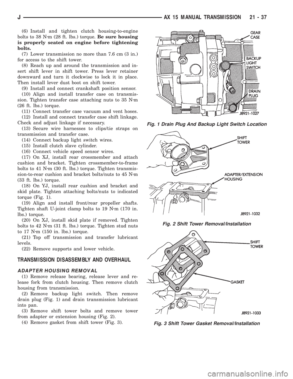
(3) Remove shift tower bolts and remove tower
from adapter or extension housing (Fig. 2).
(4) Remove gasket from shift tower (Fig. 3).
Fig. 1 Drain Plug And Backup Light Switch Location
Fig. 2 Shift Tower Removal/Installation
Fig. 3 Shift Tower Gasket Removal/Installation
JAX 15 MANUAL TRANSMISSION 21 - 37