tow JEEP XJ 1995 Service And Repair Manual
[x] Cancel search | Manufacturer: JEEP, Model Year: 1995, Model line: XJ, Model: JEEP XJ 1995Pages: 2158, PDF Size: 81.9 MB
Page 1820 of 2158
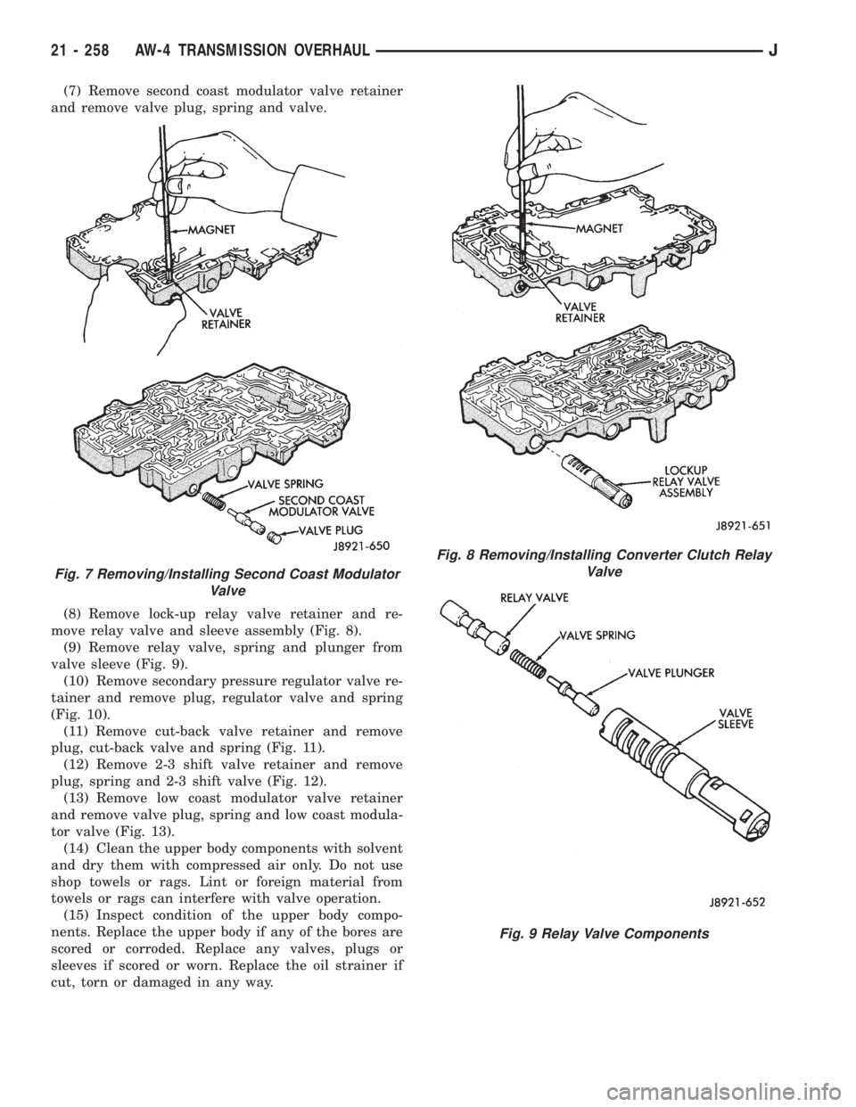
(7) Remove second coast modulator valve retainer
and remove valve plug, spring and valve.
(8) Remove lock-up relay valve retainer and re-
move relay valve and sleeve assembly (Fig. 8).
(9) Remove relay valve, spring and plunger from
valve sleeve (Fig. 9).
(10) Remove secondary pressure regulator valve re-
tainer and remove plug, regulator valve and spring
(Fig. 10).
(11) Remove cut-back valve retainer and remove
plug, cut-back valve and spring (Fig. 11).
(12) Remove 2-3 shift valve retainer and remove
plug, spring and 2-3 shift valve (Fig. 12).
(13) Remove low coast modulator valve retainer
and remove valve plug, spring and low coast modula-
tor valve (Fig. 13).
(14) Clean the upper body components with solvent
and dry them with compressed air only. Do not use
shop towels or rags. Lint or foreign material from
towels or rags can interfere with valve operation.
(15) Inspect condition of the upper body compo-
nents. Replace the upper body if any of the bores are
scored or corroded. Replace any valves, plugs or
sleeves if scored or worn. Replace the oil strainer if
cut, torn or damaged in any way.
Fig. 7 Removing/Installing Second Coast Modulator
Valve
Fig. 8 Removing/Installing Converter Clutch Relay
Valve
Fig. 9 Relay Valve Components
21 - 258 AW-4 TRANSMISSION OVERHAULJ
Page 1829 of 2158
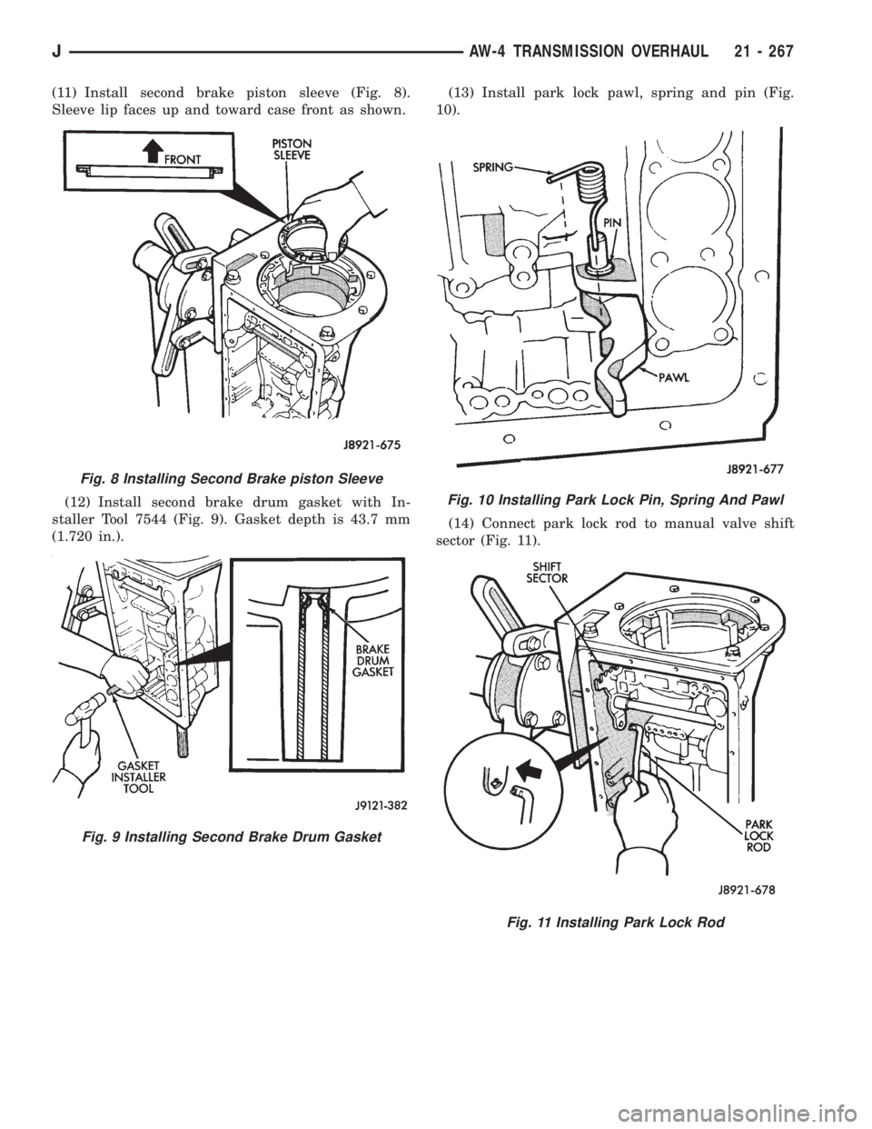
(11) Install second brake piston sleeve (Fig. 8).
Sleeve lip faces up and toward case front as shown.
(12) Install second brake drum gasket with In-
staller Tool 7544 (Fig. 9). Gasket depth is 43.7 mm
(1.720 in.).(13) Install park lock pawl, spring and pin (Fig.
10).
(14) Connect park lock rod to manual valve shift
sector (Fig. 11).
Fig. 8 Installing Second Brake piston Sleeve
Fig. 9 Installing Second Brake Drum Gasket
Fig. 10 Installing Park Lock Pin, Spring And Pawl
Fig. 11 Installing Park Lock Rod
JAW-4 TRANSMISSION OVERHAUL 21 - 267
Page 1830 of 2158
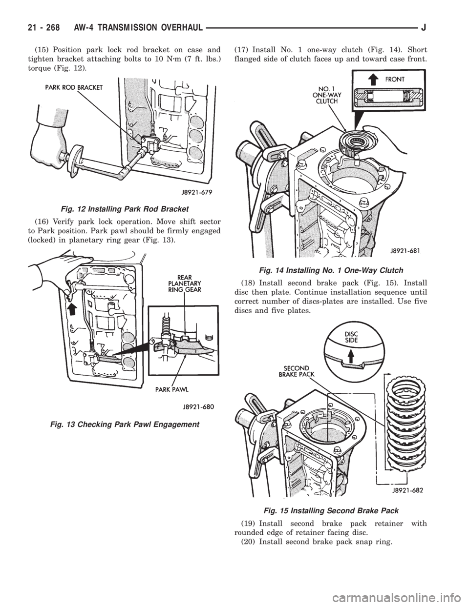
(15) Position park lock rod bracket on case and
tighten bracket attaching bolts to 10 Nzm (7 ft. lbs.)
torque (Fig. 12).
(16) Verify park lock operation. Move shift sector
to Park position. Park pawl should be firmly engaged
(locked) in planetary ring gear (Fig. 13).(17) Install No. 1 one-way clutch (Fig. 14). Short
flanged side of clutch faces up and toward case front.
(18) Install second brake pack (Fig. 15). Install
disc then plate. Continue installation sequence until
correct number of discs-plates are installed. Use five
discs and five plates.
(19) Install second brake pack retainer with
rounded edge of retainer facing disc.
(20) Install second brake pack snap ring.
Fig. 12 Installing Park Rod Bracket
Fig. 13 Checking Park Pawl Engagement
Fig. 14 Installing No. 1 One-Way Clutch
Fig. 15 Installing Second Brake Pack
21 - 268 AW-4 TRANSMISSION OVERHAULJ
Page 1832 of 2158
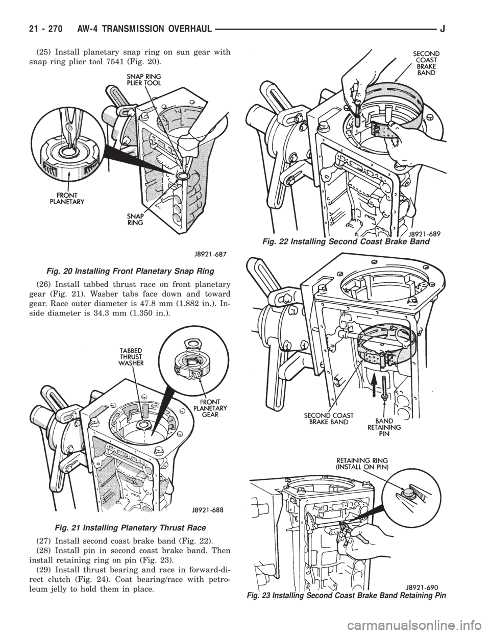
(25) Install planetary snap ring on sun gear with
snap ring plier tool 7541 (Fig. 20).
(26) Install tabbed thrust race on front planetary
gear (Fig. 21). Washer tabs face down and toward
gear. Race outer diameter is 47.8 mm (1.882 in.). In-
side diameter is 34.3 mm (1.350 in.).
(27) Install second coast brake band (Fig. 22).
(28) Install pin in second coast brake band. Then
install retaining ring on pin (Fig. 23).
(29) Install thrust bearing and race in forward-di-
rect clutch (Fig. 24). Coat bearing/race with petro-
leum jelly to hold them in place.
Fig. 22 Installing Second Coast Brake Band
Fig. 23 Installing Second Coast Brake Band Retaining Pin
Fig. 20 Installing Front Planetary Snap Ring
Fig. 21 Installing Planetary Thrust Race
21 - 270 AW-4 TRANSMISSION OVERHAULJ
Page 1833 of 2158
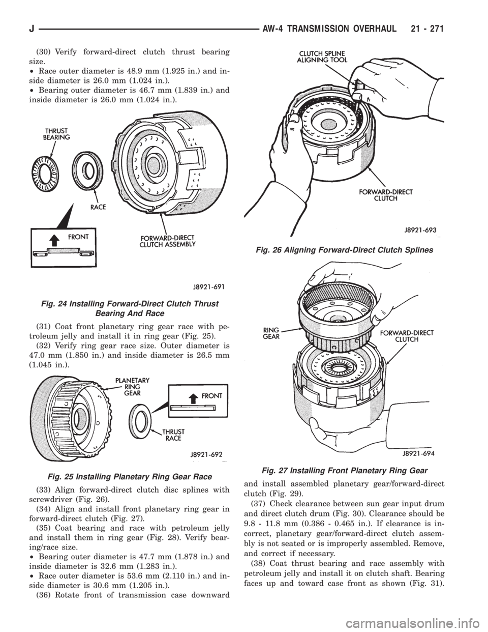
(30) Verify forward-direct clutch thrust bearing
size.
²Race outer diameter is 48.9 mm (1.925 in.) and in-
side diameter is 26.0 mm (1.024 in.).
²Bearing outer diameter is 46.7 mm (1.839 in.) and
inside diameter is 26.0 mm (1.024 in.).
(31) Coat front planetary ring gear race with pe-
troleum jelly and install it in ring gear (Fig. 25).
(32) Verify ring gear race size. Outer diameter is
47.0 mm (1.850 in.) and inside diameter is 26.5 mm
(1.045 in.).
(33) Align forward-direct clutch disc splines with
screwdriver (Fig. 26).
(34) Align and install front planetary ring gear in
forward-direct clutch (Fig. 27).
(35) Coat bearing and race with petroleum jelly
and install them in ring gear (Fig. 28). Verify bear-
ing/race size.
²Bearing outer diameter is 47.7 mm (1.878 in.) and
inside diameter is 32.6 mm (1.283 in.).
²Race outer diameter is 53.6 mm (2.110 in.) and in-
side diameter is 30.6 mm (1.205 in.).
(36) Rotate front of transmission case downwardand install assembled planetary gear/forward-direct
clutch (Fig. 29).
(37) Check clearance between sun gear input drum
and direct clutch drum (Fig. 30). Clearance should be
9.8 - 11.8 mm (0.386 - 0.465 in.). If clearance is in-
correct, planetary gear/forward-direct clutch assem-
bly is not seated or is improperly assembled. Remove,
and correct if necessary.
(38) Coat thrust bearing and race assembly with
petroleum jelly and install it on clutch shaft. Bearing
faces up and toward case front as shown (Fig. 31).
Fig. 24 Installing Forward-Direct Clutch Thrust
Bearing And Race
Fig. 25 Installing Planetary Ring Gear Race
Fig. 26 Aligning Forward-Direct Clutch Splines
Fig. 27 Installing Front Planetary Ring Gear
JAW-4 TRANSMISSION OVERHAUL 21 - 271
Page 1836 of 2158
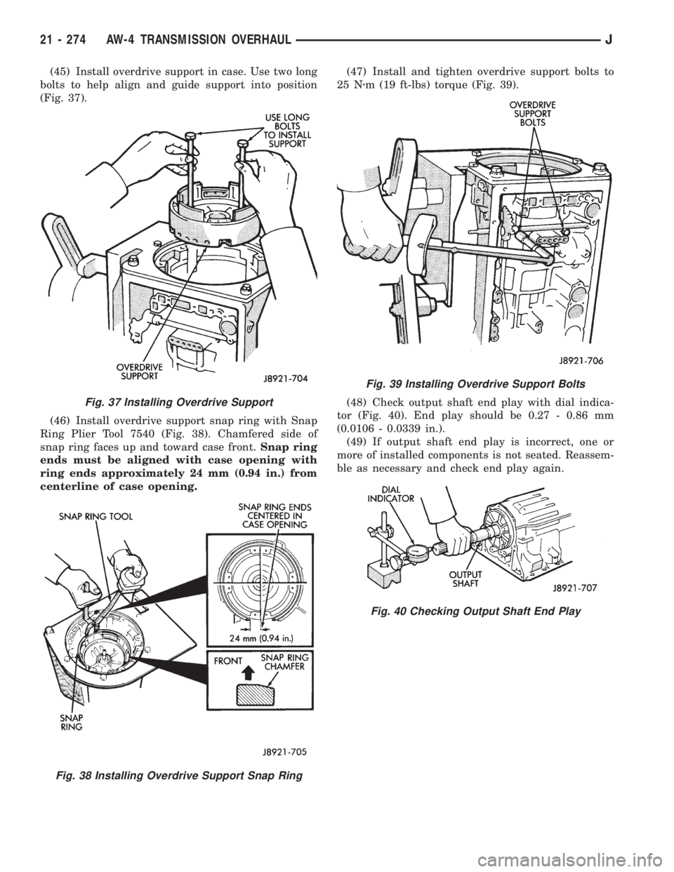
(45) Install overdrive support in case. Use two long
bolts to help align and guide support into position
(Fig. 37).
(46) Install overdrive support snap ring with Snap
Ring Plier Tool 7540 (Fig. 38). Chamfered side of
snap ring faces up and toward case front.Snap ring
ends must be aligned with case opening with
ring ends approximately 24 mm (0.94 in.) from
centerline of case opening.(47) Install and tighten overdrive support bolts to
25 Nzm (19 ft-lbs) torque (Fig. 39).
(48) Check output shaft end play with dial indica-
tor (Fig. 40). End play should be 0.27 - 0.86 mm
(0.0106 - 0.0339 in.).
(49) If output shaft end play is incorrect, one or
more of installed components is not seated. Reassem-
ble as necessary and check end play again.
Fig. 37 Installing Overdrive Support
Fig. 38 Installing Overdrive Support Snap Ring
Fig. 39 Installing Overdrive Support Bolts
Fig. 40 Checking Output Shaft End Play
21 - 274 AW-4 TRANSMISSION OVERHAULJ
Page 1863 of 2158
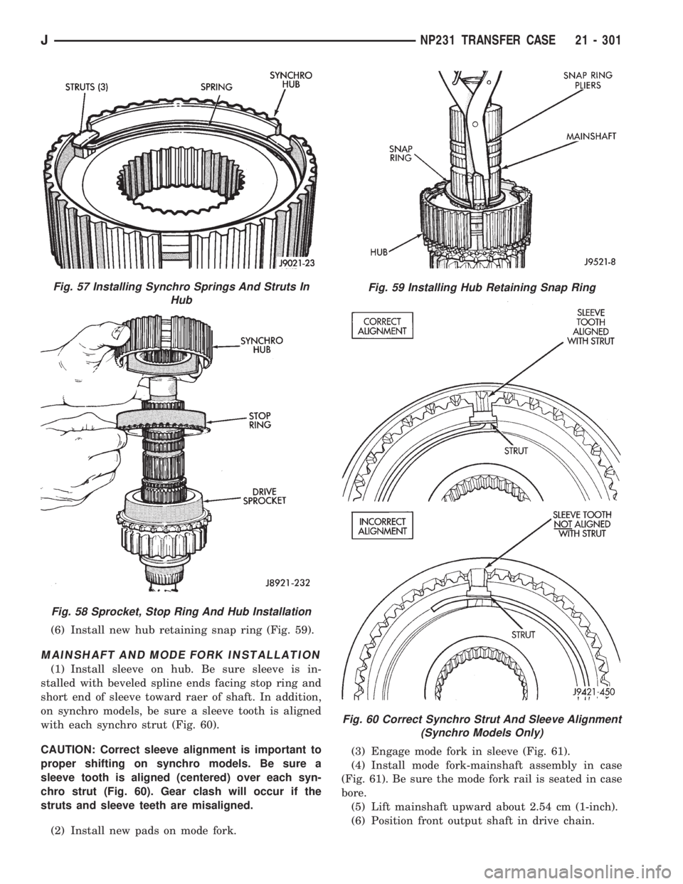
(6) Install new hub retaining snap ring (Fig. 59).
MAINSHAFT AND MODE FORK INSTALLATION
(1) Install sleeve on hub. Be sure sleeve is in-
stalled with beveled spline ends facing stop ring and
short end of sleeve toward raer of shaft. In addition,
on synchro models, be sure a sleeve tooth is aligned
with each synchro strut (Fig. 60).
CAUTION: Correct sleeve alignment is important to
proper shifting on synchro models. Be sure a
sleeve tooth is aligned (centered) over each syn-
chro strut (Fig. 60). Gear clash will occur if the
struts and sleeve teeth are misaligned.
(2) Install new pads on mode fork.(3) Engage mode fork in sleeve (Fig. 61).
(4) Install mode fork-mainshaft assembly in case
(Fig. 61). Be sure the mode fork rail is seated in case
bore.
(5) Lift mainshaft upward about 2.54 cm (1-inch).
(6) Position front output shaft in drive chain.
Fig. 57 Installing Synchro Springs And Struts In
Hub
Fig. 58 Sprocket, Stop Ring And Hub Installation
Fig. 59 Installing Hub Retaining Snap Ring
Fig. 60 Correct Synchro Strut And Sleeve Alignment
(Synchro Models Only)
JNP231 TRANSFER CASE 21 - 301
Page 1939 of 2158
(4) If the original molding will be installed, also re-
move all adhesive from it.
INSTALLATION
(1) Install 3M 06379 double-sided tape on the
molding.
(2) For vertical alignment, use masking tape or a
string as reference.
(3) Remove the backing from the tape, align the
molding and position it on the body panel.
(4) Press the molding onto the body panel with a
roller or hand pressure.
BODY STRIPES/DECALSÐXJ
SERVICE INFORMATION
XJ body stripes and decals are weather resistant
tape with a adhesive backing.
REPAIR
Small nicks, scratches and other surface marks in
a body stripe/decal can be touched-up with paint.
To eliminate blisters and air bubbles in a body
stripe/decal, pierce them with a needle or pin.
A heat gun can also be used to remove small wrin-
kles in a stripe/decal.
REQUIREMENTS
Body stripe/decal replacement requires that the
metal repair and paint refinish be completed first.
The work area temperature should be between
18ÉC (65ÉF) and 32ÉC (90ÉF).A tape stripe/decal
should not be replaced if the work area temper-
ature is less than 18ÉC (65ÉF).
The following equipment and material are neces-
sary for removal and installation:
²Commercial tape stripe/decal removal solution.
²Commercial adhesive removal solution.
²Liquid dish detergent (for the wetting solution).
²Mixture of wetting solution.
²Commercial wax and silicone removal solution.
²Isopropyl (rubbing) alcohol.
²Small squeegee (plastic or hard rubber).
²Water bucket and sponge.
²Clean wiping rags or paper towels.
²Heat gun (or infra-red heat bulb).
²Wax pencil.
²
Sharp knife, single edge razor blade or X-acto knife.
²Pair of scissors.
²Needle or pin.
The use of a wetting solution aids the installation of a
tape stripe/decal on a painted panel. Prepare the wet-
ting solution by mixing two or three teaspoons of dish
detergent with 1 gallon of water.Do not use soap.
Too much detergent will reduce the effective-
ness of the mixture.
REMOVAL
(1) Clean the repaired surface, adjacent panels and
door the openings as necessary.
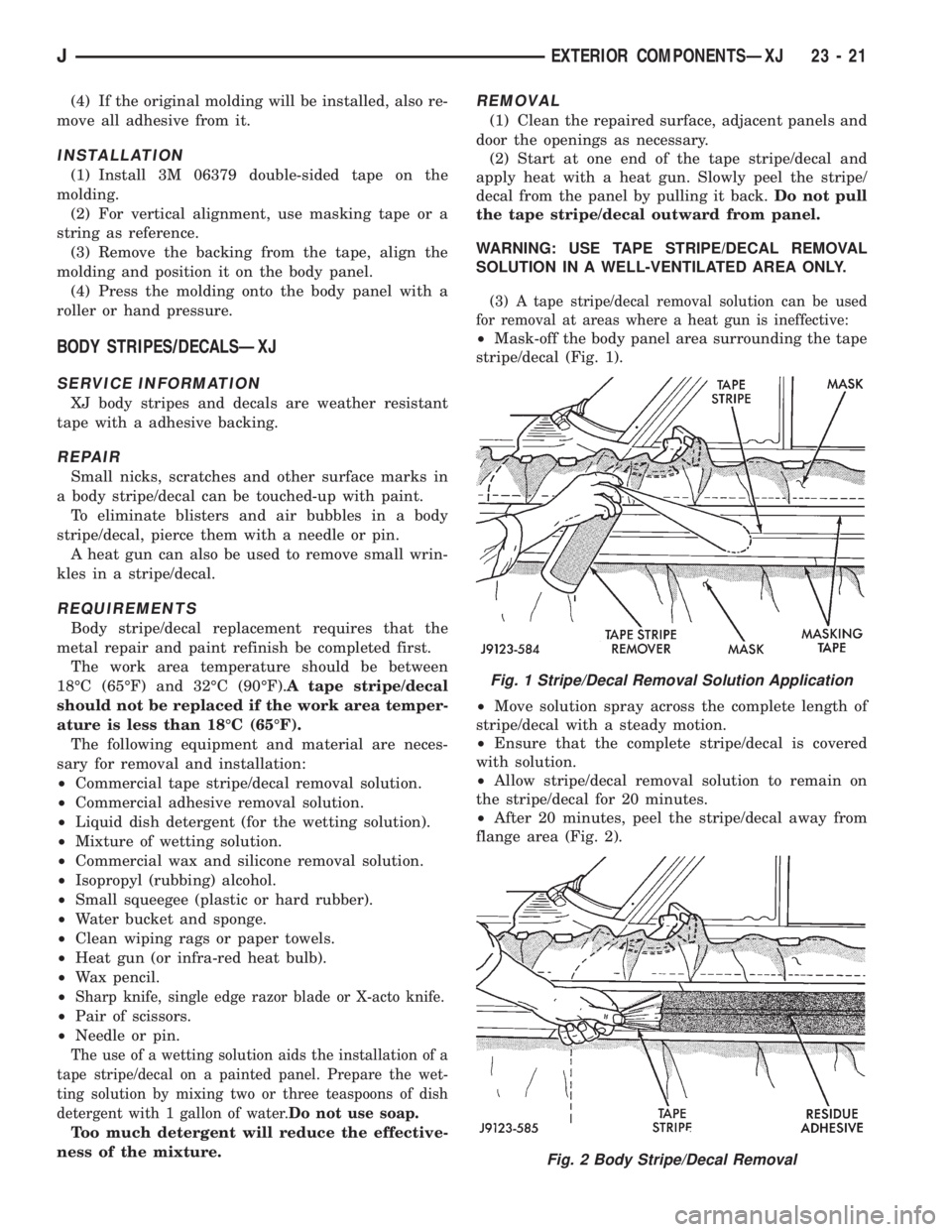
(2) Start at one end of the tape stripe/decal and
apply heat with a heat gun. Slowly peel the stripe/
decal from the panel by pulling it back.Do not pull
the tape stripe/decal outward from panel.
WARNING: USE TAPE STRIPE/DECAL REMOVAL
SOLUTION IN A WELL-VENTILATED AREA ONLY.
(3) A tape stripe/decal removal solution can be used
for removal at areas where a heat gun is ineffective:
²Mask-off the body panel area surrounding the tape
stripe/decal (Fig. 1).
²Move solution spray across the complete length of
stripe/decal with a steady motion.
²Ensure that the complete stripe/decal is covered
with solution.
²Allow stripe/decal removal solution to remain on
the stripe/decal for 20 minutes.
²After 20 minutes, peel the stripe/decal away from
flange area (Fig. 2).
Fig. 1 Stripe/Decal Removal Solution Application
Fig. 2 Body Stripe/Decal Removal
JEXTERIOR COMPONENTSÐXJ 23 - 21
Page 1981 of 2158
LIFTGATE SUPPORT ROD CYLINDER DISPOSALÐ
XJ
WARNING: SAFETY GOGGLES MUST BE WORN
DURING THE DISPOSAL PROCEDURE. THE HIGH
PRESSURE GAS CHARGE IN THE SUPPORT ROD
CYLINDERS WILL BE RELEASED DURING THE
PROCEDURE.
(1) Remove the support rod cylinder(s) from the
liftgate.
(2) Position the support rod cylinder horizontally
in a vise and clamp the cylinder securely.
(3) Wrap the cylinder with 4-5 layers of shop tow-
els.
(4) Measure 1 and 1/2 inches inward from the end
of the cylinder. Mark this location on the towels with
chalk. The cylinder will be punctured at this location
to release the gas charge.
(5) Use a punch and hammer to puncture cylinder.
Force the punch through towels and into the cylinder
with a hammer. Continue striking the punch until
the gas begins to escapebut do not remove the
punch.
(6) Hold the towels and punch in position until all
the gas has escaped. Complete de-pressurization will
require about 4 to 10 seconds. After all the gas has
escaped, slowly remove the punch.
(7) Hold a towel over the hole in cylinder and press
the support rod piston all the way into the cylinder
to purge remaining oil.
(8) Remove the support rod cylinder from the vise
and discard it.
(9) If both support rod cylinders are being re-
placed, repeat this procedure for the remaining cylin-
der.
LIFTGATE SUPPORT ROD BALL STUD
REPLACEMENTÐXJ
REMOVAL
(1) Open the liftgate.
(2) Support the liftgate in the open position.
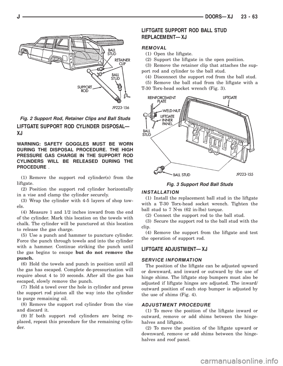
(3) Remove the retainer clip that attaches the sup-
port rod and cylinder to the ball stud.
(4) Disconnect the support rod from the ball stud.
(5) Remove the ball stud from the liftgate with a
T-30 Torx-head socket wrench (Fig. 3).
INSTALLATION
(1) Install the replacement ball stud in the liftgate
with a T-30 Torx-head socket wrench. Tighten the
ball stud to 7 Nzm (62 in-lbs) torque.
(2) Connect the support rod to the ball stud.
(3) Secure the support rod to the ball stud with the
clip.
(4) Remove the support from the liftgate and test
the operation of support rod.
LIFTGATE ADJUSTMENTÐXJ
SERVICE INFORMATION
The position of the liftgate can be adjusted upward
or downward, and inward or outward by the use of
hinge shims. The liftgate stop bumpers must also be
adjusted if liftgate hinges are adjusted. The inward/
outward position of each stop bumper is adjusted by
the use of shims (Fig. 4).
ADJUSTMENT PROCEDURE
(1) To move the position of the liftgate inward or
outward, remove or add shims between the hinge-
halves and liftgate.
(2) To move the position of the liftgate upward or
downward, remove or add shims between the hinge-
halves and roof panel.
Fig. 2 Support Rod, Retainer Clips and Ball Studs
Fig. 3 Support Rod Ball Studs
JDOORSÐXJ 23 - 63
Page 1984 of 2158
STATIONARY WINDOW GLASS
INDEX
page page
Interior Rearview MirrorÐXJ Removal and
Installation............................. 66
Interior Rearview Mirror Support Bracket
ReplacementÐXJ Preparation and Installation . . . 66
Description and Operation.......... ..........67
InstallationÐShort Method.......... ..........69
InstallationÐExtended Method........ ........71Rear Door Stationary Window Glass...... ......72
Rear Quarter Vent Window GlassÐXJ Removal
and Installation............. .............73
Rear Quarter Window Glass/Rear Quarter Plastic
InsertÐXJ Removal and Installation..... .....73
INTERIOR REARVIEW MIRRORÐXJ
MIRROR REMOVAL
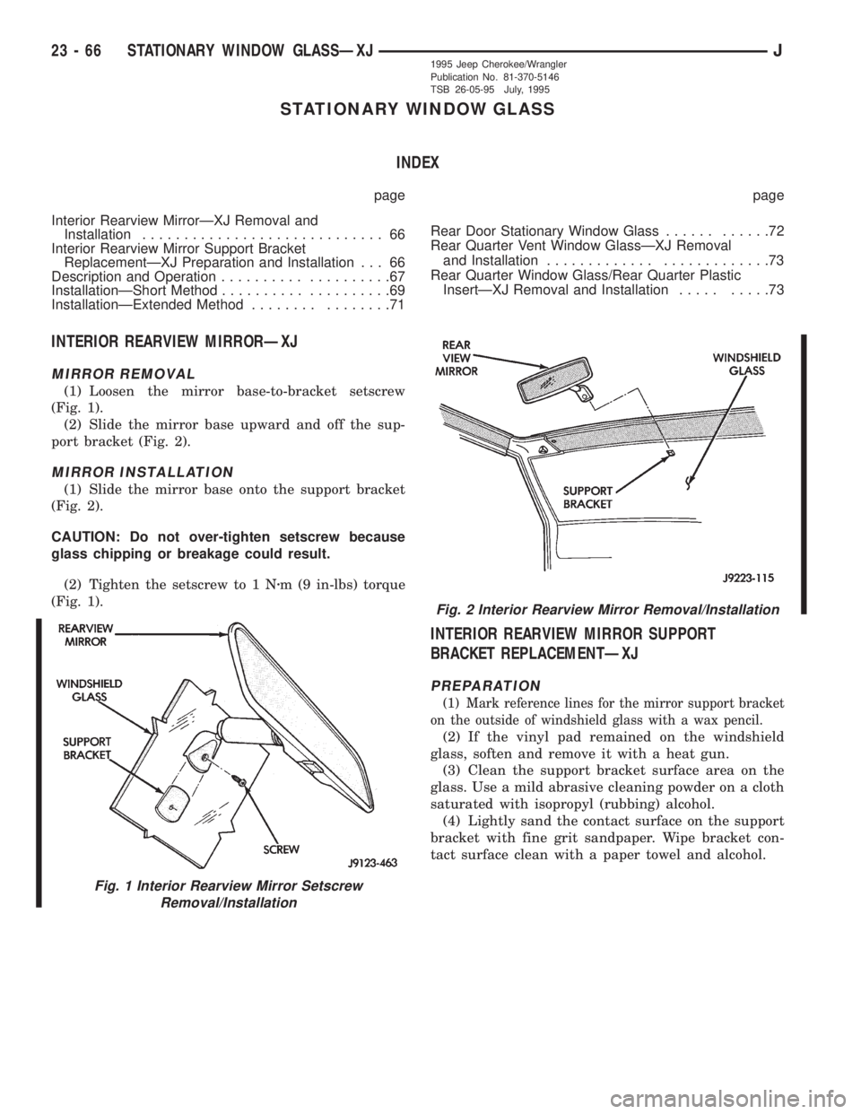
(1) Loosen the mirror base-to-bracket setscrew
(Fig. 1).
(2) Slide the mirror base upward and off the sup-
port bracket (Fig. 2).
MIRROR INSTALLATION
(1) Slide the mirror base onto the support bracket
(Fig. 2).
CAUTION: Do not over-tighten setscrew because
glass chipping or breakage could result.
(2) Tighten the setscrew to 1 Nzm (9 in-lbs) torque
(Fig. 1).
INTERIOR REARVIEW MIRROR SUPPORT
BRACKET REPLACEMENTÐXJ
PREPARATION
(1) Mark reference lines for the mirror support bracket
on the outside of windshield glass with a wax pencil.
(2) If the vinyl pad remained on the windshield
glass, soften and remove it with a heat gun.
(3) Clean the support bracket surface area on the
glass. Use a mild abrasive cleaning powder on a cloth
saturated with isopropyl (rubbing) alcohol.
(4) Lightly sand the contact surface on the support
bracket with fine grit sandpaper. Wipe bracket con-
tact surface clean with a paper towel and alcohol.
Fig. 1 Interior Rearview Mirror Setscrew
Removal/Installation
Fig. 2 Interior Rearview Mirror Removal/Installation
23 - 66 STATIONARY WINDOW GLASSÐXJJ1995 Jeep Cherokee/Wrangler
Publication No. 81-370-5146
TSB 26-05-95 July, 1995