relay JEEP XJ 1995 Service And Repair Manual
[x] Cancel search | Manufacturer: JEEP, Model Year: 1995, Model line: XJ, Model: JEEP XJ 1995Pages: 2158, PDF Size: 81.9 MB
Page 1467 of 2158
INSTALLATION
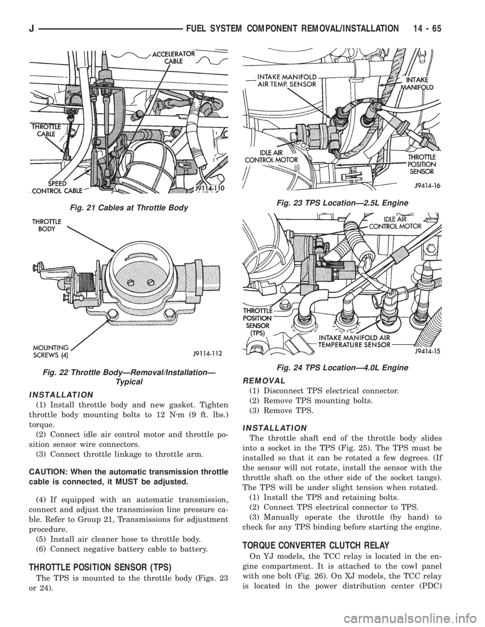
(1) Install throttle body and new gasket. Tighten
throttle body mounting bolts to 12 Nzm (9 ft. lbs.)
torque.
(2) Connect idle air control motor and throttle po-
sition sensor wire connectors.
(3) Connect throttle linkage to throttle arm.
CAUTION: When the automatic transmission throttle
cable is connected, it MUST be adjusted.
(4) If equipped with an automatic transmission,
connect and adjust the transmission line pressure ca-
ble. Refer to Group 21, Transmissions for adjustment
procedure.
(5) Install air cleaner hose to throttle body.
(6) Connect negative battery cable to battery.
THROTTLE POSITION SENSOR (TPS)
The TPS is mounted to the throttle body (Figs. 23
or 24).
REMOVAL
(1) Disconnect TPS electrical connector.
(2) Remove TPS mounting bolts.
(3) Remove TPS.
INSTALLATION
The throttle shaft end of the throttle body slides
into a socket in the TPS (Fig. 25). The TPS must be
installed so that it can be rotated a few degrees. (If
the sensor will not rotate, install the sensor with the
throttle shaft on the other side of the socket tangs).
The TPS will be under slight tension when rotated.
(1) Install the TPS and retaining bolts.
(2) Connect TPS electrical connector to TPS.
(3) Manually operate the throttle (by hand) to
check for any TPS binding before starting the engine.
TORQUE CONVERTER CLUTCH RELAY
On YJ models, the TCC relay is located in the en-
gine compartment. It is attached to the cowl panel
with one bolt (Fig. 26). On XJ models, the TCC relay
is located in the power distribution center (PDC)
Fig. 21 Cables at Throttle Body
Fig. 22 Throttle BodyÐRemoval/InstallationÐ
Typical
Fig. 23 TPS LocationÐ2.5L Engine
Fig. 24 TPS LocationÐ4.0L Engine
JFUEL SYSTEM COMPONENT REMOVAL/INSTALLATION 14 - 65
Page 1468 of 2158
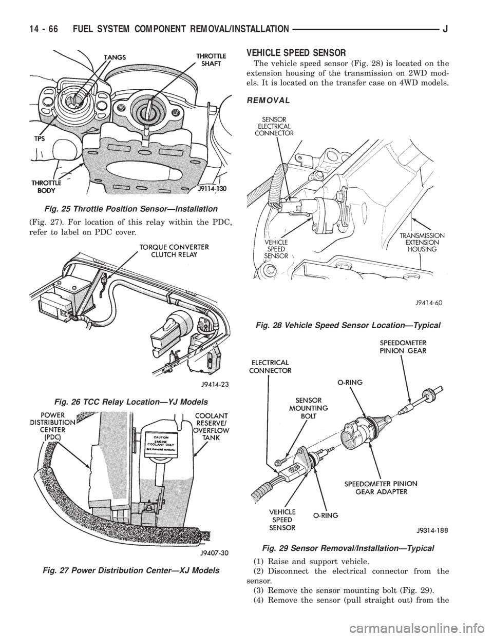
(Fig. 27). For location of this relay within the PDC,
refer to label on PDC cover.
VEHICLE SPEED SENSOR
The vehicle speed sensor (Fig. 28) is located on the
extension housing of the transmission on 2WD mod-
els. It is located on the transfer case on 4WD models.
REMOVAL
(1) Raise and support vehicle.
(2) Disconnect the electrical connector from the
sensor.
(3) Remove the sensor mounting bolt (Fig. 29).
(4) Remove the sensor (pull straight out) from the
Fig. 25 Throttle Position SensorÐInstallation
Fig. 26 TCC Relay LocationÐYJ Models
Fig. 27 Power Distribution CenterÐXJ Models
Fig. 28 Vehicle Speed Sensor LocationÐTypical
Fig. 29 Sensor Removal/InstallationÐTypical
14 - 66 FUEL SYSTEM COMPONENT REMOVAL/INSTALLATIONJ
Page 1536 of 2158
(4) From the end of travel, rotate the rotor 2 1/2
full turns in the COUNTER CLOCKWISE direction.
The horn wire should end up at the top and the
squib wire at the bottom (Fig. 9).
(5) Install the steering wheel and air bag module,
refer to Steering Wheel Installation.
COLUMN ASSEMBLY REPLACEMENT
CAUTION: Bumping, jolting and hammering on the
steering column shaft and gear shift tube must be
avoided during all service procedures.
REMOVAL
(1) Make sure the front wheels are in thestraight
aheadposition.
(2) Observe Cautions and disconnect the negative
(ground) cable from the battery.
(3) Disarm airbag, refer to Arming/Disarming Air-
bag in this section.
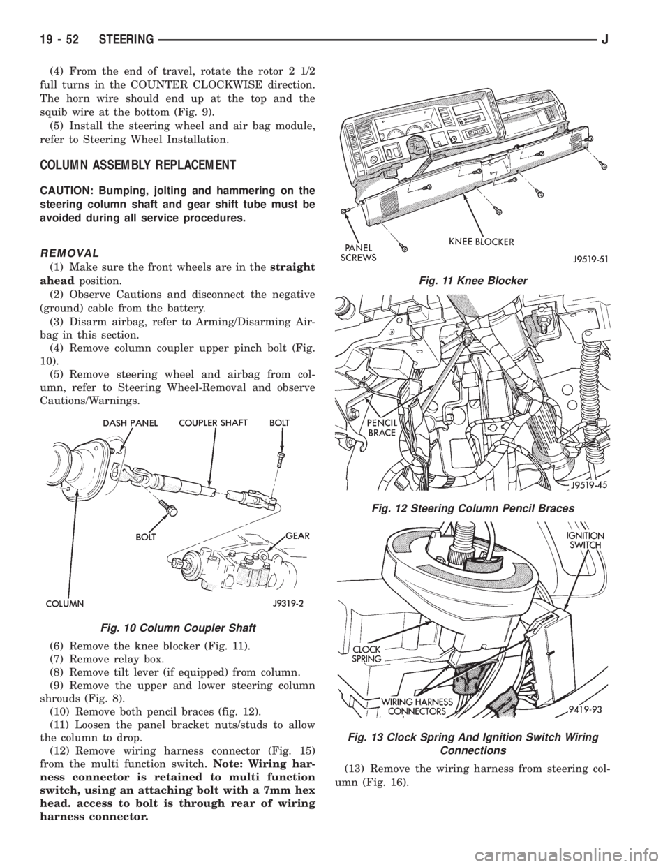
(4) Remove column coupler upper pinch bolt (Fig.
10).
(5) Remove steering wheel and airbag from col-
umn, refer to Steering Wheel-Removal and observe
Cautions/Warnings.
(6) Remove the knee blocker (Fig. 11).
(7) Remove relay box.
(8) Remove tilt lever (if equipped) from column.
(9) Remove the upper and lower steering column
shrouds (Fig. 8).
(10) Remove both pencil braces (fig. 12).
(11) Loosen the panel bracket nuts/studs to allow
the column to drop.
(12) Remove wiring harness connector (Fig. 15)
from the multi function switch.Note: Wiring har-
ness connector is retained to multi function
switch, using an attaching bolt with a 7mm hex
head. access to bolt is through rear of wiring
harness connector.(13) Remove the wiring harness from steering col-
umn (Fig. 16).
Fig. 10 Column Coupler Shaft
Fig. 11 Knee Blocker
Fig. 12 Steering Column Pencil Braces
Fig. 13 Clock Spring And Ignition Switch Wiring
Connections
19 - 52 STEERINGJ
Page 1631 of 2158
driven by the torque converter. The converter is con-
nected to the engine crankshaft through the drive-
plate.
The pressure regulator valve maintains line pres-
sure. The regulator valve is located in the valve body.
The amount of line pressure developed is controlled
by throttle pressure, which is dependent on the de-
gree of throttle opening.
The governor valve is operated by the transmission
output shaft. Governor pressure increases approxi-
mately in proportion to vehicle speed.
The throttle valve determines line pressure and
shift speed. The throttle valve also controls upshift
and downshift speeds by regulating pressure in con-
junction with throttle position.
Shift Valves
The manual valve is operated by the gearshift link-
age and provides the operating range selected by the
driver.
The 1-2 shift valve provides automatic 1-2 or 2-1
shifts and the 2-3 shift valve provides automatic 2-3
or 3-2 shifts. The kickdown valve provides forced 3-2
or 3-1 downshifts depending on vehicle speed. Down-
shifts occur when the throttle is opened beyond
downshift detent position which is just before wide
open throttle.
The 2-3 valve throttle pressure plug provides 3-2
downshifts with varying throttle openings and de-
pending on vehicle speed. The 1-2 shift control valve
transmits 1-2 shift pressure to the accumulator pis-
ton to control kickdown band capacity on 1-2 upshifts
and 3-2 downshifts.The shuttle valve has two functions. First is fast
front band release and smooth engagement during
lift-foot 2-3 upshifts. The second is to regulate front
clutch and band application during 3-2 downshifts.
Clutches-Bands-Servos-Accumulator
The front/rear clutch pistons and servo pistons are
actuated by line pressure. When line pressure is re-
moved, the pistons are released by spring tension.
On 2-3 upshifts, the front servo piston is released
by spring tension and hydraulic pressure. The accu-
mulator controls hydraulic pressure on the apply side
of the front servo during 1-2 upshifts and at all
throttle openings.
Converter Clutch Controls
Converter clutch operation is controlled by the
power train control module, and by the solenoid and
clutch module on the valve body. The solenoid is op-
erated by a relay on the engine compartment side of
the dash panel.
Activating the solenoid opens a vent allowing fluid
to flow into the clutch module. When line pressure
exceeds tension of the module valve springs, the
module valves open. This allows fluid to be chan-
neled to the converter clutch through the reaction
shaft support and transmission shaft.
Gearshift And Park Lock Controls
The gearshift lever provides six operating positions:
Park (P), Reverse (R), Neutral (N), and the D, 2 and
1 forward drive ranges.
Manual 1 position provides first gear only. Overrun
braking occurs in 1 range when the throttle is re-
leased. Upshifts are not provided in 1 range.
Manual 2 range provides first and second gear. A
1-2 upshift will take place but a 2-3 upshift will not
occur.
D position provides 1-2, 2-3 upshifts and 3-2 and
3-1 downshifts.
Park position allows the park rod to move the park
pawl into engagement with the park gear. This pre-
vents rotation of the transmission output shaft. The
park lock mechanism is only engaged when the shift
lever is in the Park detent.
A park/neutral position switch controls engine
starting. The switch is designed to allow engine
starts only in park or neutral positions.
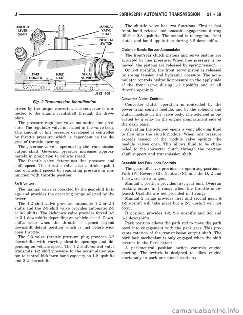
Fig. 2 Transmission Identification
J30RH/32RH AUTOMATIC TRANSMISSION 21 - 69
Page 1728 of 2158
ranges. Third gear ratio is 1:1. A separate planetary
gear set provides overdrive operation in fourth gear.
TRANSMISSION RANGES AND SHIFT LEVER
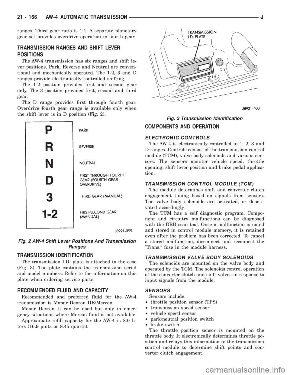
POSITIONS
The AW-4 transmission has six ranges and shift le-
ver positions. Park, Reverse and Neutral are conven-
tional and mechanically operated. The 1-2, 3 and D
ranges provide electronically controlled shifting.
The 1-2 position provides first and second gear
only. The 3 position provides first, second and third
gear.
The D range provides first through fourth gear.
Overdrive fourth gear range is available only when
the shift lever is in D position (Fig. 2).
TRANSMISSION IDENTIFICATION
The transmission I.D. plate is attached to the case
(Fig. 3). The plate contains the transmission serial
and model numbers. Refer to the information on this
plate when ordering service parts.
RECOMMENDED FLUID AND CAPACITY
Recommended and preferred fluid for the AW-4
transmission is Mopar Dexron IIE/Mercon.
Mopar Dexron II can be used but only in emer-
gency situations where Mercon fluid is not available.
Approximate refill capacity for the AW-4 is 8.0 li-
ters (16.9 pints or 8.45 quarts).
COMPONENTS AND OPERATION
ELECTRONIC CONTROLS
The AW-4 is electronically controlled in 1, 2, 3 and
D ranges. Controls consist of the transmission control
module (TCM), valve body solenoids and various sen-
sors. The sensors monitor vehicle speed, throttle
opening, shift lever position and brake pedal applica-
tion.
TRANSMISSION CONTROL MODULE (TCM)
The module determines shift and converter clutch
engagement timing based on signals from sensors.
The valve body solenoids are activated, or deacti-
vated accordingly.
The TCM has a self diagnostic program. Compo-
nent and circuitry malfunctions can be diagnosed
with the DRB scan tool. Once a malfunction is noted
and stored in control module memory, it is retained
even after the problem has been corrected. To cancel
a stored malfunction, disconnect and reconnect the
9Trans.9fuse in the module harness.
TRANSMISSION VALVE BODY SOLENOIDS
The solenoids are mounted on the valve body and
operated by the TCM. The solenoids control operation
of the converter clutch and shift valves in response to
input signals from the module.
SENSORS
Sensors include:
²throttle position sensor (TPS)
²transmission speed sensor
²vehicle speed sensor
²park/neutral position switch
²brake switch
The throttle position sensor is mounted on the
throttle body. It electronically determines throttle po-
sition and relays this information to the transmission
control module to determine shift points and con-
verter clutch engagement.
Fig. 2 AW-4 Shift Lever Positions And Transmission
Ranges
Fig. 3 Transmission Identification
21 - 166 AW-4 AUTOMATIC TRANSMISSIONJ
Page 1729 of 2158
The transmission speed sensor consists of a rotor
and magnet on the transmission output shaft and a
switch in the extension housing or adapter. The sen-
sor switch is activated each time the rotor and mag-
net complete one revolution. Sensor signals are sent
to the transmission control module.
The park/neutral position switch is mounted on the
valve body manual shaft. The switch signals shift
linkage and manual valve position to the transmis-
sion control module through an interconnecting har-
ness. The switch prevents engine starting in all gears
other than Park or Neutral.
The brake switch is in circuit with the torque con-
verter clutch solenoid. The switch disengages the
converter clutch whenever the brakes are applied.
The switch is mounted on the brake pedal bracket
and signals the transmission control module when
the pedal is pressed or released.
TORQUE CONVERTER
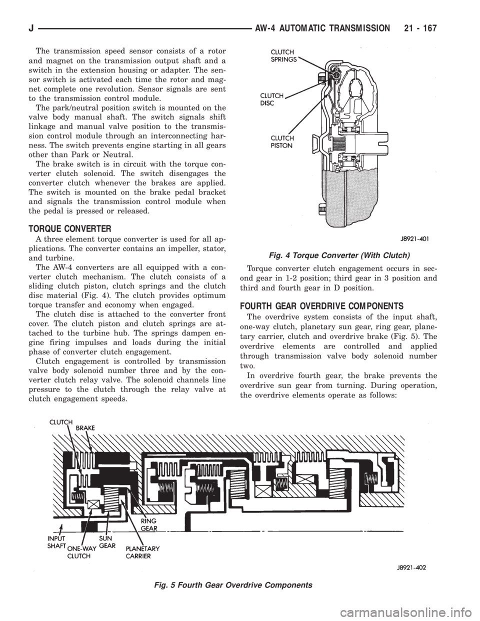
A three element torque converter is used for all ap-
plications. The converter contains an impeller, stator,
and turbine.
The AW-4 converters are all equipped with a con-
verter clutch mechanism. The clutch consists of a
sliding clutch piston, clutch springs and the clutch
disc material (Fig. 4). The clutch provides optimum
torque transfer and economy when engaged.
The clutch disc is attached to the converter front
cover. The clutch piston and clutch springs are at-
tached to the turbine hub. The springs dampen en-
gine firing impulses and loads during the initial
phase of converter clutch engagement.
Clutch engagement is controlled by transmission
valve body solenoid number three and by the con-
verter clutch relay valve. The solenoid channels line
pressure to the clutch through the relay valve at
clutch engagement speeds.Torque converter clutch engagement occurs in sec-
ond gear in 1-2 position; third gear in 3 position and
third and fourth gear in D position.
FOURTH GEAR OVERDRIVE COMPONENTS
The overdrive system consists of the input shaft,
one-way clutch, planetary sun gear, ring gear, plane-
tary carrier, clutch and overdrive brake (Fig. 5). The
overdrive elements are controlled and applied
through transmission valve body solenoid number
two.
In overdrive fourth gear, the brake prevents the
overdrive sun gear from turning. During operation,
the overdrive elements operate as follows:
Fig. 4 Torque Converter (With Clutch)
Fig. 5 Fourth Gear Overdrive Components
JAW-4 AUTOMATIC TRANSMISSION 21 - 167
Page 1734 of 2158
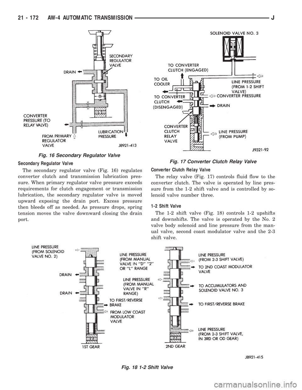
Secondary Regulator Valve
The secondary regulator valve (Fig. 16) regulates
converter clutch and transmission lubrication pres-
sure. When primary regulator valve pressure exceeds
requirements for clutch engagement or transmission
lubrication, the secondary regulator valve is moved
upward exposing the drain port. Excess pressure
then bleeds off as needed. As pressure drops, spring
tension moves the valve downward closing the drain
port.Converter Clutch Relay Valve
The relay valve (Fig. 17) controls fluid flow to the
converter clutch. The valve is operated by line pres-
sure from the 1-2 shift valve and is controlled by so-
lenoid valve number three.
1-2 Shift Valve
The 1-2 shift valve (Fig. 18) controls 1-2 upshifts
and downshifts. The valve is operated by the No. 2
valve body solenoid and line pressure from the man-
ual valve, second coast modulator valve and the 2-3
shift valve.
Fig. 16 Secondary Regulator Valve
Fig. 17 Converter Clutch Relay Valve
Fig. 18 1-2 Shift Valve
21 - 172 AW-4 AUTOMATIC TRANSMISSIONJ
Page 1820 of 2158
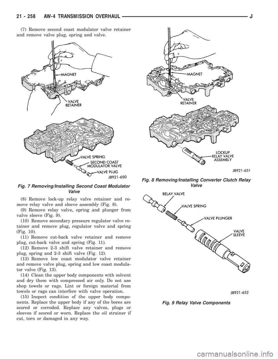
(7) Remove second coast modulator valve retainer
and remove valve plug, spring and valve.
(8) Remove lock-up relay valve retainer and re-
move relay valve and sleeve assembly (Fig. 8).
(9) Remove relay valve, spring and plunger from
valve sleeve (Fig. 9).
(10) Remove secondary pressure regulator valve re-
tainer and remove plug, regulator valve and spring
(Fig. 10).
(11) Remove cut-back valve retainer and remove
plug, cut-back valve and spring (Fig. 11).
(12) Remove 2-3 shift valve retainer and remove
plug, spring and 2-3 shift valve (Fig. 12).
(13) Remove low coast modulator valve retainer
and remove valve plug, spring and low coast modula-
tor valve (Fig. 13).
(14) Clean the upper body components with solvent
and dry them with compressed air only. Do not use
shop towels or rags. Lint or foreign material from
towels or rags can interfere with valve operation.
(15) Inspect condition of the upper body compo-
nents. Replace the upper body if any of the bores are
scored or corroded. Replace any valves, plugs or
sleeves if scored or worn. Replace the oil strainer if
cut, torn or damaged in any way.
Fig. 7 Removing/Installing Second Coast Modulator
Valve
Fig. 8 Removing/Installing Converter Clutch Relay
Valve
Fig. 9 Relay Valve Components
21 - 258 AW-4 TRANSMISSION OVERHAULJ
Page 1822 of 2158
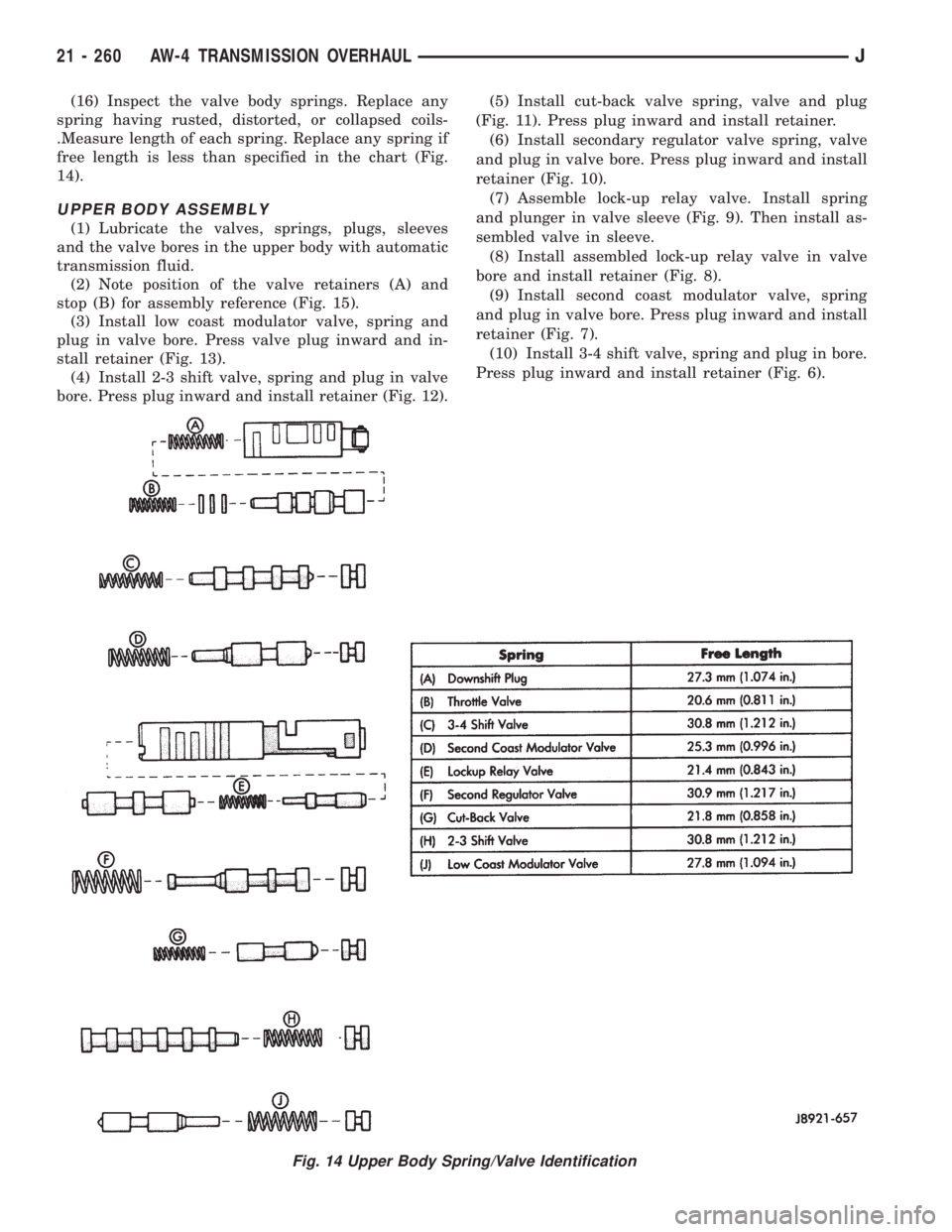
(16) Inspect the valve body springs. Replace any
spring having rusted, distorted, or collapsed coils-
.Measure length of each spring. Replace any spring if
free length is less than specified in the chart (Fig.
14).
UPPER BODY ASSEMBLY
(1) Lubricate the valves, springs, plugs, sleeves
and the valve bores in the upper body with automatic
transmission fluid.
(2) Note position of the valve retainers (A) and
stop (B) for assembly reference (Fig. 15).
(3) Install low coast modulator valve, spring and
plug in valve bore. Press valve plug inward and in-
stall retainer (Fig. 13).
(4) Install 2-3 shift valve, spring and plug in valve
bore. Press plug inward and install retainer (Fig. 12).(5) Install cut-back valve spring, valve and plug
(Fig. 11). Press plug inward and install retainer.
(6) Install secondary regulator valve spring, valve
and plug in valve bore. Press plug inward and install
retainer (Fig. 10).
(7) Assemble lock-up relay valve. Install spring
and plunger in valve sleeve (Fig. 9). Then install as-
sembled valve in sleeve.
(8) Install assembled lock-up relay valve in valve
bore and install retainer (Fig. 8).
(9) Install second coast modulator valve, spring
and plug in valve bore. Press plug inward and install
retainer (Fig. 7).
(10) Install 3-4 shift valve, spring and plug in bore.
Press plug inward and install retainer (Fig. 6).
Fig. 14 Upper Body Spring/Valve Identification
21 - 260 AW-4 TRANSMISSION OVERHAULJ
Page 1995 of 2158
TRAILER HITCH
TRAILER HITCHÐXJ
CLASS III HITCH
A class III weight-distributing/equalizer type hitch
can be used to tow a trailer:
²Having a maximum gross weight of 5,000 lbs/2250
kg.
²Having a maximum tongue weight of 750 lbs/332
kg).
The following vehicle basic equipment is required
for class III trailer towing:
²P205/75R15 or larger tires.
²Full size spare tire.
²Trailer sway control.
²Trailer tow wire harness and connector.
²Heavy duty turn signal flasher element.
²Heavy duty axle (with synthetic lubricant).
²Heavy duty cooling system.
²Heavy duty generator/battery.
²Auxiliary automatic transmission fluid cooler.
²I-6, 4.0L engine.
Wide-angle type door mirrors are recommended but
not required.
WIRE HARNESS CONNECTORS
CLASS I HITCH CONNECTOR
The trailer tow wire harness connector for class I
trailer hitches is a 5-terminal, in-line type connector.
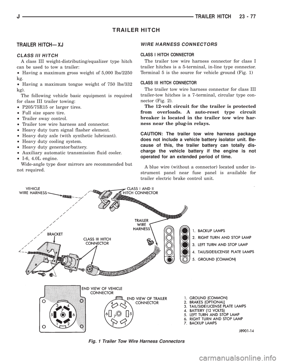
Terminal 5 is the source for vehicle ground (Fig. 1)
CLASS III HITCH CONNECTOR
The trailer tow wire harness connector for class III
trailer-tow hitches is a 7-terminal, circular type con-
nector (Fig. 2).
The 12-volt circuit for the trailer is protected
from overloads. A auto-reset type circuit
breaker is located in the trailer tow wire har-
ness near the plug-in relays.
CAUTION: The trailer tow wire harness package
does not include a vehicle battery isolator unit. Be-
cause of this, the trailer battery can totally dis-
charge the vehicle battery if the engine is not
operated for an extended period of time.
A blue wire (without a connector) located under in-
strument panel near fuse panel is available for
trailer electric brake control unit.
Fig. 1 Trailer Tow Wire Harness Connectors
JTRAILER HITCH 23 - 77